SAFT
In recent years, the adoption of linear array transducers
and the use of synthetic aperture imaging has expanded
considerably for non-destructive testing, leading to the
introduction of the full matrix capture data acquisition
technique and the total focusing method. Based on the
underlying principles of the synthetic aperture focusing
technique, it is capable of producing higher resolution
images, but at the cost of lower frame rates. For time-critical
inspections, this paper outlines an alternative synthetic
aperture method, termed virtual source aperture (VSA).
To measure performance in terms of speed, full matrix
capture, synthetic aperture focusing and the virtual source
aperture are compared experimentally, where it is shown
that the virtual source aperture offers rapid inspection times
with images of good lateral resolution and signal-to-noise
ratio.
Keywords: ultrasonics, arrays, post-processing, data processing, full matrix capture, synthetic aperture focusing technique, synthetic transmit aperture.
1. Introduction
The use of array transducers in the field of ultrasonic non-destructive testing (NDT) is now commonplace[1] and they are routinely used for lab- and site-based inspections across a range of fields, including oil, gas, power generation, aerospace and marine. The main attraction of arrays over conventional single-crystal transducers is their ability to electronically focus, steer and sweep ultrasonic energy with an almost infinite number of combinations. There are several benefits which can result from this: electronic beam steering and sweeping minimises mechanical transducer movement, improving the inspection coverage on components with limited surface access.
These arrays may be used to emulate a monolithic transducer[2] or configured to allow for sweeping through a range of angles, as used in phased array. This is accomplished through independently controlling the timing at which each element is fired to produce a high-intensity plane wave in the direction of beam propagation, allowing for real-time B-scan images to be generated. An alternative
approach is to have each element treated as an individual transducer in its own right with wave propagation carried out sequentially, where only energy from a single point source is present in the medium at any one time, allowing for synthetic aperture focusing techniques (SAFT) to be applied during post-processing. While both principles have been previously explored in depth, with the latter leading to the introduction of full matrix capture (FMC), this paper presents an approach that emulates a virtual point source during transmission, with receiving data captured using traditional synthetic aperture (SA) data acquisition techniques, where received signals are collected independently by the individual elements.
A contributing factor in the adoption of a new ultrasonic technique is that of frame rate, where real-time inspections are preferable. For conventional synthetic aperture systems this is often a trade-off between resolution and speed, where for phased array this involves reducing the number of beams per frame, and for SAFT reducing pixel resolution. However, the data acquisition method must also be considered to reduce the post-processing requirement of the SA algorithms and, to adequately characterise the features of each of these techniques, it is first necessary to define the underlying mathematical principles involved and provide a brief history of the development of synthetic aperture. The algorithms considered are: conventional SAFT, full matrix capture and virtual source aperture (VSA).
2. Synthetic aperture
Synthetic aperture ultrasound imaging for NDT is becoming commonplace. It is a technique that synthetically simulates a virtual aperture from a series of smaller elements, either through a multi-element transducer or tracking the movement of a single-element transducer. Imaging of synthetic aperture data is achieved through the implementation of a post-processing algorithm, which is dependent on the focusing requirements of the inspection.
While the basic post-processing and imaging algorithms used within NDT and the medical world have evolved from early radar imaging systems, they have been adapted to suit the environment in which they are used. For example, medical ultrasound, where it is necessary to examine dynamically moving organs such as the heart, where high frame rates in excess of 50 frames per second (fps) is a requirement[3], often requires higher frame rates than are required within NDT. While lower frame rates would be acceptable within NDT, a different set of problems exist in that NDT components are metallic or composite in nature. Often, however, it is the same basic algorithms used in all fields but referred to by different names[4], leading to confusion among non-specialists. Two synthetic aperture techniques (SAFT and TFM) are discussed in this section before a review of the VSA technique.
2.1 Conventional SAFT
Synthetic aperture first appeared in the 1950s[5] as part of a radar imaging system and is a technique that post-processes an unfocused collection of signals over time to achieve better resolution than could otherwise be achieved. Conventionally, SAFT collects
Virtual source aperture imaging for non-destructive
testing
M Sutcliffe, M Weston, P Charlton, B Dutton and K Donne Submitted 10.05.12 Accepted 06.06.12
Mark Sutcliffe is with Swansea Metropolitan University, Mt Pleasant Campus, Mt Pleasant, Swansea SA1 6ED, UK and TWI NDT Validation
Centre (Wales), ECM2, Heol Cefn Gwrgan, Margam, Port Talbot SA13 2EZ,
UK.
Peter Charlton and Kelvin Donne are with Swansea Metropolitan University.
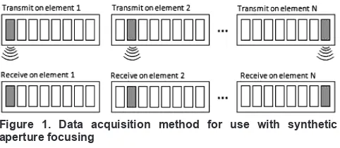
coherent pulse-echo data over the scanned area with a synthetic array implemented during post-processing. In its simplest implementation this would involve a single element transmitting, then receiving, an unfocused wave, which in itself would produce a low-resolution image, but when combined with data from a larger number of elements higher resolutions are possible. This ability to focus the array everywhere within an image allows for greater lateral resolution and depth of field than could be obtained with traditional linear B-scanning methods. More recently, the application of SAFT with multiple-element array transducers allows for faster data acquisition (when compared to physical scanning of single-element transducers) through reduced mechanical movement[3]. This data acquisition process is described in Figure 1, where it can be seen that energy is transmitted and received by each transducer element in turn.
The imaging of data with SAFT is achieved through a delay and sum beamforming approach, whereby a grid of pixels representative of the region of interest is defined, with summing of the time domain signals contributing to pixel intensities for each grid location. Therefore, for every focal x, z point there will be a contribution from n time-of-flight calculations (where n represents the number of active elements), which is used to extract the relevant amplitude information from the array of data. Since every pixel in the image acts as a focal point, fully-focused imagery of the region of interest can be obtained, as illustrated in Figure 2.
Expressed mathematically in Equation (1), pixel intensities (I) are determined from the time-of-flight calculation from each rx element to each x, z pixel location, where c is the velocity. A Hilbert transform (h) is optionally used here to convert the real time domain signal into complex form, which allows the signal magnitude (envelope) to be found:
I x,z
( )
= hrx 2 xrx −x(
)
2+z2 c ⎛ ⎝ ⎜ ⎜ ⎞ ⎠ ⎟ ⎟
∑
summed for all rx ...(1)The transmission pattern of conventional SAFT can be shown theoretically to generate a beam pattern with a very narrow main lobe offering high lateral resolution. However, this is at the cost of poor sidelobe suppression, which can reduce the achievable signal-to-noise ratio[6]. Reduction of the sidelobe level is possible through the application of apodisation weights, but only at the cost of increasing the main lobe width[7].
2.2 Full matrix capture
The advancement of conventional SAFT to allow for every possible transmit and receive combination of a multi-element transducer directly led to the development of the total focusing method (TFM) and FMC. First introduced to NDT in 2005[2], it applies a ‘transmit on one and receive on all’ data acquisition strategy (as illustrated in Figure 3). The data is acquired sequentially as each element first acts as a transmitter with all elements acting as receivers, allowing for every possible transmit and receive combination to be exploited, introducing greater angular coverage, but at the cost of a larger data size of n2.
As expressed in Equation (2), imaging of FMC data is identical to that of SAFT[8], except that the contribution to pixel intensity for FMC is determined from each transmit tx and receive rx pair, allowing for a significant improvement in the signal-to-noise ratio over that of conventional SAFT. Examination of this strategy reveals that conventional SAFT imaging can be obtained by taking the diagonal of the FMC dataset, and that by accounting for reciprocity of the pitch-catch time domain signals a reduced size of rx/2(rx+1) is possible[9]. That is, for each tx, rx pair, the corresponding rx, tx can be determined from the original tx, rx pair:
I x,z( )= htx,rx xtx
−x
(
)
2+z2+ x rx−x
(
)
2+z2 c ⎛ ⎝ ⎜ ⎜ ⎞ ⎠ ⎟ ⎟
∑
summed for all tx,rx ..(2)A limiting factor in the adoption of FMC is that the performance of the post-processing algorithm and data acquisition strategy result in much slower frame rates than those of traditional ultrasonic methods due to the larger number of time domain signals to be processed. While the algorithm is highly suited for improved computational time through parallelisation, the number of transmission cycles is of particular importance as it sets a fundamental limit at which the system can operate.
3. Virtual source aperture
By treating the focus of the transducer as a virtual source for synthetic aperture processing, improvements in lateral resolution beyond the focus of the transducer are possible[7]. A technique first explored by Karman and O’Donnell[10] for use with medical ultrasound, it has not been fully exploited for use with NDT. It is presented here as an additional synthetic aperture imaging approach that allows for faster data acquisition than FMC and conventional SAFT, by reducing the number of transmission cycles necessary to produce an image.
A virtual source is selected away from the transducer to act as a source of spherical waves, which is used to determine the appropriate delay in the firing of each physical transducer element of the linear array. This delay pattern is determined by calculating the path length from each transducer element to this virtual source simply by using Pythagoras theorem and subtracting the shortest path length to produce a result to provide a set of values relating to the order and timing of each transducer element. These path lengths are converted to time to determine the inter-element time of firing as expressed in Figure 4 and Equation (3), where D is the delay
Figure 1. Data acquisition method for use with synthetic aperture focusing
Figure 2. Imaging with the synthetic aperture focusing technique, where every pixel acts as a focal point with intensity values calculated from the summed contribution from all receiving elements
value for transmit element tx at location x and pz is the position of the virtual source:
Dtx= xtx
2+pz2−pz
c ...(3) The VSA method discussed here allows for a divergent beam to propagate through the material as if transmitting from a virtual point source above the array. The centre elements fire first, with the outer elements firing last. This technique differs from phased array ultrasonics in that a focal point may be defined within the material (below the array) to generate a beam that converges at the point of focus. The reception of data is similar to that of FMC data acquisition in that each transducer element will act as a receiver, allowing for n A-scans to contribute to the imaging algorithm. However, unlike conventional SAFT, only a single transmission pulse is necessary.
Imaging of the virtual source data is accomplished through a variation of the standard SAFT algorithm (previously discussed) and is expressed in Equation (4), where each time-of-flight calculation is made relative to the centre element of the transducer (the point at which the virtual source is first emitted):
I x,z
( )
= hrx x2+z2+ x
rx−x
(
)
2+z2c ⎛
⎝ ⎜ ⎜
⎞
⎠ ⎟ ⎟
∑
summed for all rx ...(4)While the VSA algorithm is shown to produce datasets of identical size to those of conventional SAFT (n), it is collected from only a single transmission cycle, allowing for faster data acquisition and a reduction in the time that ultrasonic energy is present in the material. This has the benefit of allowing for the rapid inspection of components.
4. Experimental configuration and results
VSA was experimentally tested and compared with SAFT and TFM to determine the quality of the image and the speed of inspection. For this purpose, an experimental data acquisition and post-processing system was assembled consisting of:(a) A data acquisition system controlled by a MicroPulse 5PA array controller manufactured by Peak NDT, Derby. The system contained separate transmit and receive lines per channel and facilitated the use of parallel and sequential transmission techniques. The data acquisition rate via Ethernet of this system was established as approximately 7 MB/s according to the manufacturer’s specification.
(b) A GE Inspection Technologies 32-element linear array
transducer with a 5 MHz central frequency. Data was sampled at a rate of 25 MHz with an 8-bit amplitude resolution for all 32 elements.
(c) A Windows 7-based PC containing an Intel Core i3 CPU running at 2.4 GHz and equipped with 3 GB of RAM.
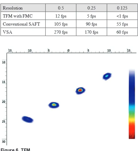
The test sample used for this work was a ferritic steel block of dimensions 35 × 35 × 120 mm and manufactured from low-carbon steel (see Figure 5). This sample contained four equally-spaced (5 mm), diagonally-aligned 3 mm side-drilled holes (SDH) along a 60 degree plane relative to the normal at a depth of 12-26 mm. Acquisition and post-processing was performed on this specimen for 32 active elements and set to image an area of –15 mm to +15 mm horizontally and 10 mm to 30 mm vertically at resolutions of 0.5, 0.25 and 0.125, producing images of pixel sizes 60 × 40, 120 × 80 and 240 × 160, respectively. A threshold of 20 dB was applied to the images, with reconstruction of the raw data performed in C++ for optimal performance and presentation of images through the Windows Presentation Foundation (WPF).
For the VSA algorithm, the position of the virtual source was set at –30 mm vertical to the normal. This location was selected to minimise the beam spread relative to the aperture of the physical transducer and the region of interest while allowing the maximum amount of energy to be transmitted. For each algorithm the test was repeated to the above specification, with results presented in Table 1 and Figures 6 to 9 (all images are rendered with a 20 dB threshold and 30 dB gain, unless otherwise stated).
Table 1. Frame rates for TFM, SAFT and VSA for experimental configuration
Resolution 0.5 0.25 0.125
TFM with FMC 12 fps 5 fps <1 fps Conventional SAFT 105 fps 90 fps 55 fps
VSA 270 fps 170 fps 60 fps
Figure 4. Calculation for delay pattern, where pz is the distance of the virtual source from the transducer and tx is the x coordinate of each transducer element (all measurements are relative to the centre of the transducer)
Figure 5. Test sample used for experimental configuration
5. Discussion
Analysis of the experiment confirms that performance (measured in frames per second) was best for the VSA algorithm, and that this was possible due to the reduction in data acquisition time due to the single transmission cycle needed to generate an image. Images from VSA were comparable to those of TFM in terms of image resolution, but suffered from the introduction of noise. However, the higher frame rates of VSA and the single transmission strategy (which reduced the time ultrasonic energy was present in the material) allowed for faster physical movement of the transducer
without the introduction of motion artifacts, which was shown to be present with conventional SAFT and TFM.
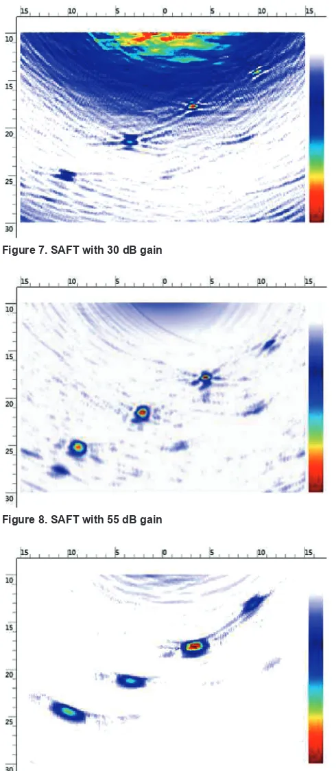
Unlike conventional phased array systems (where all elements are fired to form a beam with a fixed focus), the VSA method utilised a single virtual point source positioned above the array, which generated a divergent beam that was not focused within the material. A single virtual source was used and positioned so that it would allow the maximum transfer of energy relative to the region of interest. An advantage with conventional SAFT and TFM is that pixel intensity over a wide area is more uniform due to the contribution from a larger number of individual transmit and receive element combinations within the array. Where only a single virtual point source is used on transmission, degradation of the image occurs near the edges (where the pixel is far away from the axis virtual point source). This can be seen in Figure 9, where only one side-drilled hole achieved maximum intensity. A solution to this would be to introduce an additional or an array of additional VSA sources to provide greater angular coverage.
It should be noted that while Figures 7 and 8 (conventional SAFT) suffered from lower signal-to-noise ratio, it achieved a higher resolution for each SDH. The poor signal-to-noise ratio was present in these images as the SAFT algorithm implemented here is based on each transducer element firing sequentially, and it was more common to coherently sum elements to increase the virtual aperture size, that is a group of elements firing in parallel and electronically shifted along the width of the aperture. This technique was not explored here as the focus of the experiment was to determine performance in relation to speed, therefore minimum processing time was explored.
6. Conclusion
This work presented three synthetic aperture techniques: SAFT, TFM and VSA, with the objective of determining the performance of each algorithm inclusive of data acquisition, image render and image quality. To achieve this, each technique was presented in detail describing its data acquisition strategy and post-processing algorithm, where it was shown that each technique evolved from the same basic principle as that of conventional SAFT.
Each algorithm was implemented on an experimental data acquisition and post-processing system capable of data transfer speeds of 7 MB/s, with post-processing carried out under C++ for optimal performance. It was shown that while TFM offers the best possible image quality of the techniques discussed, VSA outperformed TFM and SAFT in terms of speed, with similar image quality to that of TFM.
Acknowledgements
This work was completed in partnership with TWI NDT Validation Centre (Wales), Swansea Metropolitan University, the University of Wales and the Prince of Wales Innovation Scholarship Scheme (POWIS).
References
1. R/D Tech, Introduction to Phased Array Ultrasonic Technology Applications, R/D Tech guideline, Advanced Practical NDT Series, R/D Tech Corp, 2004.
2. C Holmes, B Drinkwater and P Wilcox, ‘Post-processing of the full matrix of ultrasonic transmit/receive array data for non-destructive evaluation’, NDT&E International, 38 (8), pp 701-711, 2005. doi:10.1016/j.ndteint.2005.04.002
3. I Trots, Y Tasinkevych, A Nowicki and M Lewandowski, ‘Multi-element synthetic transmit aperture method in medical ultrasound imaging’, Engineering and Technology, pp 201-206, 2011.
4. P T Gough and D W Hawkins, ‘Unified framework for modern synthetic aperture imaging algorithms’, International Journal
Figure 8. SAFT with 55 dB gain
Figure 9. VSA
of Imaging Systems and Technology, 8 (4), pp 343-358, 1997. 5. J A Jensen, S I Nikolov, K L Gammelmark and M H Pedersen,
‘Synthetic aperture ultrasound imaging’, Ultrasonics, 44, Suppl 1, pp e5-e15, 2006.
6. F Foster and G Lockwood, ‘Optimising two-dimensional transducer arrays using an effective aperture approach’, IEEE Ultrasonics Symposium Proceedings, pp 1497-1501, 1994. 7. C H Frazier and W R O’Brien, ‘Synthetic aperture techniques
with a virtual source element’, IEEE Transactions on Ultrasonics, Ferroelectrics and Frequency Control, 45 (1), pp 196-207, 1998.
8. J Zhang, B W Drinkwater, P D Wilcox and A J Hunter, ‘Defect detection using ultrasonic arrays: the multi-mode total focusing method’, NDT&E International, 43 (2), pp 123-133, 2010. doi:10.1016/j.ndteint.2009.10.001
9. C Holmes, B W Drinkwater and P D Wilcox, ‘Advanced post-processing for scanned ultrasonic arrays: application to defect detection and classification in non-destructive evaluation’, Ultrasonics, 48 (6-7), pp 636-642, 2008. doi:10.1016/j. ultras.2008.07.019