A New Network Slicing Framework for
Multi-Tenant Heterogeneous Cloud Radio Access
Networks
Ying Loong Lee
∗, Jonathan Loo
†and Teong Chee Chuah
∗∗Faculty of Engineering, Multimedia University, 63100 Cyberjaya, Selangor, Malaysia
Email: [email protected], [email protected]
†School of Science and Technology, Middlesex University, London NW4 4BT, United Kingdom
Email: [email protected]
Abstract—Research on network slicing for multi-tenant het-erogeneous cloud radio access networks (H-CRANs) is still in its infancy. In this paper, we redefine network slicing and propose a new network slicing framework for multi-tenant H-CRANs. In particular, the network slicing process is formulated as a weighted throughput maximization problem that involves sharing of computational resources, fronthaul capacity, physical remote radio heads and radio resources. The problem is then jointly solved using a sub-optimal greedy approach and a dual decomposition method. Simulation results demonstrate that the framework can flexibly scale the throughput performance of multiple tenants according to the user priority weights associated with the tenants.
I. INTRODUCTION
In the past decade, the demand for broadband multimedia services has been increasing explosively. With this ongoing trend, the revenue of mobile network operators will soon be exceeded by the capital expenditure (CAPEX) and the operating expenditure (OPEX) required to operate the infras-tructure. In view of this predicament, several radio access network (RAN) architectures have been proposed for the next generation mobile cellular networks. Particularly, the cloud-RANs (C-cloud-RANs) have attracted much interest from academia and industry.
In a C-RAN, the baseband units (BBUs) of all remote radio heads (RRHs) are centralized at a single BBU pool via optical fronthaul links. In this architecture, the upper-layer baseband functions are carried out by the BBU pool whereas the RRHs performs radio transmission to the users. The C-RAN architecture can achieve significant reduction in energy consumption and higher throughput while providing flexibility and scalability in network deployment [1]. All of these features lead to reductions in the CAPEX and OPEX. The C-RAN architecture has further been adapted to heterogeneous cellular systems, leading to the heterogeneous C-RAN (H-CRAN) architecture consisting of a macro base station (MBS) and low-power RRHs (small cells) [2]. This architecture relieves the control signaling burden of the RRHs and delivers higher spectral and energy efficiency to the network. Currently, inten-sive research has been carried out for developing H-CRANs.
While C-RANs are being intensively studied, multi-tenancy has recently emerged as an interesting concept for a C-RAN shared by multiple mobile virtual network operators (VNOs) who do not own the RAN infrastructure. The basic idea of multi-tenancy is to allow multiple VNOs to share a physical RAN infrastructure. In fact, this RAN sharing can be viewed as a RAN-as-a-service (RANaaS) business model and the VNOs are known as the tenants. The idea of multi-tenancy is equivalent to multi-operator RAN sharing [3]–[5]. However, the implementation of infrastructure sharing in C-RANs require network and resource virtualization [6], [7]. In the context of network virtualization, a virtual network created for a tenant is called anetwork slicewhich consists of a set of data flows sharing a physical RAN with multiple other virtual networks. Currently, development in this area is still in its infancy, especially the implementation of multi-tenancy in C-RANs, thus forming the core of study of this paper. In the following, we provide a background review of multi-operator RAN sharing and multi-tenancy.
resource allocation framework is designed to perform capacity allocation between VNOs.
Nevertheless, despite these research efforts, numerous is-sues remain to be addressed. Most notably, RAN sharing considered in [3]–[5], [8], [9] was mainly studied under the traditional cellular architecture, which will no longer be able to support the current rapidly growing demand for broadband multimedia services. Moreover, the studies in [3]–[5], [8]–[10] have mainly focused on sharing capacity, spectrum, physical resource blocks (PRBs) and BSs whereas the computational resources in the BBU pool and the capacity of the fronthaul links have not been considered as part of the resource sharing among multiple tenants. Therefore, a comprehensive virtual resource management and network slicing framework for multi-tenant C-RANs is non-existent, this forms the motivation of our work.
In this paper, we define network slicing as a network virtualization and sharing process in which the computational resources of the BBU pool, the capacity of the fronthaul links, the wireless radio resources and the physical RRHs are shared among multiple tenants. Our objective is to design a comprehensive virtual resource management framework for small cell networks. In particular, we focus on the downlink and consider the H-CRAN architecture as the base of this study. The main contributions are summarized as follows:
1) We propose a system model of multi-tenant H-CRANs and redefine network slicing as a process of sharing computational resources of the BBU pool, the fronthaul capacity, the radio resources and the physical RRHs among the tenants.
2) We formulate the resource allocation problem as a weighted sum rate maximization problem whereby the weights corresponds to the priority of the tenants, subject to the constraints of fronthaul capacity, computational capacity of virtual machines (VMs), transmission power, user association, user admission and co-tier interference constraints.
3) We show that the resource allocation problem is a non-convex mixed-integer programming problem and propose an efficient resource allocation algorithm based on dual decomposition, whose complexity will also be analyzed.
The rest of this paper is organized as follows: Section II describes the proposed system model of the multi-tenant H-CRAN and formulates the resource allocation problem. A sub-optimal resource allocation algorithm is developed for the problem formulated in Section III. In Section IV, performance evaluation of the proposed resource allocation framework is presented and discussed. Finally, Section V concludes the paper.
II. SYSTEMMODEL ANDPROBLEMFORMULATION
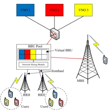
We propose a system model for a virtualized multi-tenant H-CRAN shown in Fig. 1. In this model, we quantify the computational resources of the BBU pool as the number of VMs that can be created in the BBU pool. Each VM serves
Fig. 1. Multi-tenant H-CRAN.
as the virtual BBU for each data flow. For simplicity, we assume that each data flow corresponds to one user. It is noteworthy that the computational resources of the BBU pool are limited. Thus, admission control of data flows becomes part of the resource sharing process. Here, we denoteVas the set of VMs that can be supported in the BBU pool. Another assumption is made whereby all fronthaul links have equal data rate capacity. Depending on the service-level agreement (SLA) between the H-CRAN provider and the tenant, the H-CRAN may require to ensure that a minimum data rate is achieved for each user belonging to the tenant. Here, we assume that each tenant offers an equal minimum data rate for all of its associated users. The achievable data rate is also bounded by the computational capacity of the VMs. Here, we assume that the computational capacity of all the VMs is equal and is larger than the minimum data rate required by each user.
In our system model, the H-CRAN provider has their own users to be served, aside from providing RANaaS services to the tenants. Here, we assume that these users are served by the MBS while the users associated with the tenants are served by the small-cell RRHs. In addition, the MBS relays control signals to the tenant-associated users for resource allocation. We adopt orthogonal spectrum allocation between the macro-cell and small macro-cells, thus alleviating cross-tier interference. Therefore, we only need to focus on network slicing in the small cell tier.
We denoteN as the set of tenants, S as the set of RRHs, Kas the set of sub-channels,Un as the set of users belonging to tenant n and U =S
n∈NUn. We define au as the binary admission indicator of user uwherebyau = 1indicates that user u is admitted to the network; otherwise au = 0. Also, we definebsuas the binary association indicator of useruand RRHsin whichbsu= 1indicates useruassociates with RRH
s; otherwisebsu= 0. Further, the binary assignment indicator of sub-channelkto useruassociated to RRHsis denoted by
on sub-channelk for useruis denoted bypsku. Besides, we define the following:
W(u) =wn ∀u∈ Un, (1)
where wn ∈ (0,1] is a weighting value that quantifies the priority of the users associated with tenant n.
For channel modeling, the received signal-to-interference-plus-noise ratio (SINR) of userufrom RRHson sub-channel
k is given by
Γsku= P gskupsku
i∈S\{s}
P
j∈U \{u}ajbijωikjgikjpikj+σ2 , (2)
where gsku is the channel gain between RRH s and user u on sub-channelkandσ2is the additive white Gaussian noise
(AWGN) power. The achievable data rate of useruassociated with RRH son sub-channelkis given by Shannon’s formula as
Rsku=Blog2(1 + Γsku), (3)
whereB is the bandwidth in Hz of a sub-channel. We assume that each sub-channel experiences slow and flat fading and the network is perfectly synchronized.
The network slicing problem of the virtualized multi-tenant H-CRAN can be formulated as follows:
max a,b,ω,p
X s∈S
X u∈U
W(u)aubsu X k∈K
ωskuRsku, (4)
subject to
X u∈U
aubsu X k∈K
ωskuRsku≤Rfh ∀s∈ S (4a)
aubsu X k∈K
ωskuRsku ≤aubsuRmax ∀u∈ U, s∈ S (4b)
aubsu X k∈K
ωskuRsku≥aubsuRmin,u ∀u∈ U, s∈ S (4c)
X u∈U
aubsu X k∈K
ωskupsku ≤Pmax,s ∀s∈ S (4d)
X
i∈S\{s}
X u∈U
aubiuωikugikupiku≤Imax ∀s∈ S, k∈ K (4e)
X u∈U
au≤ |V| (4f)
au X s∈S
bsu≤1 ∀u∈ U (4g)
X u∈U
aubsuωsku≤1 ∀s∈ S, k∈ K (4h)
psku≥0 ∀u∈ U, s∈ S, k∈ K (4i)
au, bsu, ωsku∈ {0,1} ∀u∈ U, s∈ S, k ∈ K, (4j)
where a = {a1, . . . , a|U |}, b = {b11, . . . , b|S||U |}, ω = {ω111, . . . , ω|S||K||U |}, p = {p111, . . . , p|S||K||U |}, W(u) is
the weight function of user u associated to its tenant, Rfh
is the fronthaul capacity, Rmax is the computational capacity of VMs, Rmin,u is the minimum data rate guaranteed for user u by its associated tenant, Pmax,s is the transmission power budget of RRH s and Imax is the predefined tolerable
interference threshold of an RRH on a sub-channel. In (4), constraint (4a) guarantees that the traffic carried by each RRH does not exceed its fronthaul capacity. Constraints (4b) and (4c) ensure that the achievable data rate of each user is bounded by the computational capacity of VMs while meeting the minimum bit rate requirement offered by the associated tenant, respectively. The transmission power of each RRH is restricted in constraint (4d). In constraint (4e), co-tier interference experienced on each sub-channel is limited by a predefined tolerable interference threshold, Imax. The number of admitted users is ensured in constraint (4f) to be not exceeding the number of VMs available in the BBU pool, i.e.,|V|, where|.|denotes the cardinality of the set. Constraint (4g) ensures that each admitted user is associated with only one RRH. Constraint (4h) enforces that no two or more users associated with the same RRH receive the same sub-channel. The transmission power of each RRH on each sub-channel is ensured to be non-negative in constraint (4i). Constraint (4j) guarantees thatau,bsuandωsku take only binary values. We observe that (4) is a non-convex mixed-integer programming problem, which is generally NP-hard. An exhaustive search is not viable in this case as the computational complexity would be of exponential time. In the next section, we design an efficient resource allocation algorithm to solve (4) based on a dual decomposition method.
III. SOLUTIONALGORITHM
To design an efficient resource allocation algorithm, we need to transform (4) into a tractable optimization problem. Firstly, we express the lower bound of the SINR that can be experienced by useruassociated with RRHson sub-channel
kas
ΓLB
sku=
pskugsku
Imax+σ2. (5)
Subsequently, the lower bound of the achievable data rate of useruassociated with RRHson sub-channelkcan be given by
RLB
sku =Blog2(1 + ΓLBsku). (6) Then, the lower bound of (4) can be written as
max a,b,ω,p
X s∈S
X u∈U
W(u)aubsu X k∈K
ωskuRLBsku, (7)
subject to (4d)-(4j) and X
u∈U
aubsu X k∈K
ωskuRLBsku≤Rfh ∀s∈ S (7a)
aubsu X k∈K
ωskuRLBsku≤aubsuRmax ∀u∈ U, s∈ S (7b)
aubsu X k∈K
ωskuRLBsku≥aubsuRmin,u ∀u∈ U, s∈ S. (7c)
Algorithm 1 User admission and association algorithm
1: Setau= 0andbsu= 0for allu∈ Uands∈ S,Uadm=∅. 2: Estimate the wideband SINR for allu∈ Uands∈ Susing (8). 3: Setbsu= 1such that the wideband SINR received by userufrom RRH
sis the largest among all other RRHs.
4: Estimate the weighted user throughput per sub-channel for all u ∈ U based on the received wideband SINR using (9).
5: Sort all the users in descending order of the weighted user throughput. 6: Add the first|V|users with the highest weighted user throughput into set
Uadm or add all users if the total number of users is less than|V|. 7: Setau= 1for allu∈ Uadm.
In Algorithm 1, we first assume that all users are not admitted and associated with any RRH, i.e., au = 0 and
bsu = 0 for all u ∈ U and s ∈ S, and Uadm is initialized as an empty set. Subsequently, we associate each user with an RRH such that the RRH provides the largest received wideband SINR to the user. The received wideband SINR can be estimated as
Γwb,su=
¯
gsuPmax,s P
i∈S\{s}g¯iuPmax,i+σ2
∀s∈ S, u∈ U, (8)
whereΓwb,su is the wideband SINR received by userufrom RRH s,¯gsu is the average channel gain between RRHsand user u across the channel bandwidth. After user association, we estimate the weighted user throughput per sub-channel based on the received wideband SINR as follows:
Rw,u= X s∈S
W(u)bsuBlog2(1 + Γwb,su). (9)
Then, the users are sorted in descending order of the weighted user throughput and the first |V| users with the highest weighted throughput values are admitted to Uadm. If the total
number of users is less than|V|, all the users will be admitted toUadm.
After solvingaandbwith Algorithm 1, the problem in (7) can be reduced to
max
ω,p
X s∈S
X u∈Us
W(u)X k∈K
ωskuRskuLB , (10)
subject to
X u∈Us
X k∈K
ωskuRLBsku≤Rfh ∀s∈ S (10a)
X k∈K
ωskuRLBsku≤Rmax ∀u∈ Us, s∈ S (10b)
X k∈K
ωskuRLBsku≥Rmin,u ∀u∈ Us, s∈ S (10c)
X u∈Us
X k∈K
ωskupsku≤Pmax,s ∀s∈ S (10d)
X
i∈S\{s}
X u∈Ui
ωikugikupiku≤Imax ∀s∈ S, k∈ K (10e)
X u∈Us
ωsku ≤1 ∀s∈ S, k ∈ K (10f)
psku ≥0 ∀u∈ Us, s∈ S, k∈ K (10g)
ωsku∈ {0,1} ∀u∈ Us, s∈ S, k ∈ K, (10h)
whereUs={u∈ U|au= 1, bsu= 1}. Thereafter, we assume that ωsku = 0 and psku = 0 for all u ∈ U\Us, s ∈ S and
k∈ K, and employ the dual decomposition method to solve (10) under the assumption that Slater’s condition is satisfied, i.e., the duality gap is zero. In fact, it has been proved that the duality gap for resource allocation in multi-carrier systems is nearly zero if the number of sub-channels is sufficiently large [11]. Therefore, the solution to (10) can be obtained by solving its dual problem.
We first write the Lagrangian function of (10) as
L(ω,p,α,β,φ,λ,µ,τ)
=X
s∈S
X u∈Us
W(u)X k∈K
ωskuRLBsku
+X
s∈S
αs Rfh− X u∈Us
X k∈K
ωskuRLBsku !
+X
s∈S
X u∈Us
βsu Rmax− X k∈K
ωskuRLBsku !
+X
s∈S
X u∈Us
φsu X k∈K
ωskuRLBsku−Rmin,u !
+X
s∈S
λs Pmax,s− X u∈Us
X k∈K
ωskupsku !
+X
s∈S
X k∈K
µsk Imax−
X i∈S\{s}
X u∈Ui
ωikugikupiku
+X
s∈S
X k∈K
τsk 1− X u∈Us
ωsku !
,
(11)
where αs, βsu, φsu, λs, µsk and τsk are the Lagrange multipliers corresponding to constraints (10a)-(10f), respec-tively. Also, α = {α1, . . . , α|S|}, β = {β11, . . . , β|S||U |},
φ = {φ11, . . . , φ|S||U |}, λ = {λ1, . . . , λ|S|}, µ =
{µ11, . . . , µ|S||K|}andτ ={τ11, . . . , τ|S||K|}. It is noteworthy
that (10g) and (10h) are boundary constraints which will be absorbed in the Karush-Kuhn-Tucker (KKT) conditions [12], [13] in which optimal solution is guaranteed. Therefore, the corresponding terms in (11) can be omitted. Then, the Lagrangian dual function can be expressed as
D(α,β,φ,λ,µ,τ) = max
ω,p L(ω,p,α,β,φ,λ,µ,τ), (12) and the dual optimization problem can be formulated as
min
α,β,φ,λ,µ,τD(α,β,φ,λ,µ,τ), (13)
subject toα,β,φ,λ,µ,τ ≥0.
To solve (13), we first assume that useru∈ Usis allocated sub-channelk, i.e., ωsku = 1. Taking the derivative of (11) with respect topsku yields the following KKT conditions:
∂L
∂psku
=ωsku(Gsku−λs)≤0, (14)
where
Gsku =
(W(u)−αs−βsu+φsu)Bgsku (Imax+σ2+p
skugsku) ln 2
− X
i∈S\{s}
µikgsku.
(16) From (14)-(15), optimal power allocation can be derived as
psku =
B(W(u)−αs−βsu+φsu)
λs+Pi∈S\{s}µikgsku
ln 2
−Imax+σ
2
gsku
+
(17) for allu∈ Us,s∈ S andk∈ K, where[x]+= max(0, x).
Taking the derivative of (11) with respect toωsku gives the following KKT conditions:
∂L
∂ωsku
=Hsku−τsk≤0, (18)
ωsku(Hsku−τsk) = 0, (19)
where
Hsku= (W(u)−αs−βsu+φsu)RLBsku
−
λs+ X i∈S\{s}
µikgsku
psku.
(20)
From (18)-(19), it is seen that Hsku−τsk ≤0 if ωsku = 0 andHsku−τsk= 0ifωsku= 1. In addition, one sub-channel can only be allocated to one user among those associated with the same RRH, cf. constraint (10f). Hence, given the optimal p, optimal sub-channel allocation can be obtained as
ωsku∗ = (
1 u∗=argmaxu
∈UsHsku
0 otherwise ∀s∈ S, k∈ K.
(21) Then, upon obtaining the solution{ω,p}, we can solve the dual problem iteratively using the sub-gradient method [14], whereby the Lagrange multipliers are updated for all u∈ Us,
s∈ S andk∈ K, as follows:
α(st+1)= "
α(st)−δ1 Rfh− X u∈Us
X k∈K
ωskuRLBsku !#+
(22a)
β(t+1)
su =
"
β(t)
su −δ2 Rmax− X k∈K
ωskuRLBsku !#+
(22b)
φ(sut+1)= "
φ(sut)−δ3 X k∈K
ωskuRLBsku−Rmin,u !#+
(22c)
λ(st+1)= "
λ(st)−δ4 Pmax,s− X u∈Us
X k∈K
ωskupsku !#+
(22d)
µ(skt+1)=
µ
(t)
sk −δ5
Imax− X i∈S\{s}
X u∈Ui
ωikugikupiku
+
,
(22e)
where α(st), βsu(t), φsu(t), λ(sut) and µ(skt) are the respective αs,
βsu, φsu, λsu and µsk at the t-th iteration, and δ1, δ2, δ3,
δ4 and δ5 are the positive step sizes that satisfy the infinite travel conditions [14]. The process of updating the solution and the Lagrange multipliers are repeated until convergence is achieved or the predefined maximum number of iterations,
Tmaxhas been executed. It is noteworthy thatτ is not updated because the corresponding KKT conditions have already been fulfilled.
In the proposed algorithm, it can be observed that the solution {a,b} is obtained after |U|(|S|+ 1) function eval-uations. On the other hand, the sub-gradient method requires
Tmax iterations for completion and 2|K|P
s∈S|Us| function
evaluations for each update of the Lagrange multipliers. Thus, the computational complexity of the proposed algorithm is of O |U|(|S|+ 1) + 2Tmax|K|P
s∈S|Us|
.
IV. RESULTS ANDDISCUSSION
In this section, we present some numerical results of the proposed network slicing framework. Here, we consider a two-tenant H-CRAN, which consists of a macrocell, with a radius of 500 m overlaid by ten pico-RRHs, which are equidistant between each other within the cell and are located at a distance of 250 m from the MBS. The number of sub-channels is set to 100 with each having a bandwidth of 180 kHz [15]. We investigate the throughput performance of the network by varying the number of users associated with the first tenant, denoted as VNO 1, while fixing the number of users associated to the second tenant, denoted as VNO 2, as 50. Other network parameters are set as follows: Rfh = 1 Mb/s, Rmax = 200 kb/s, Rmin,u = 128 kb/s for all u ∈ U, Pmax,s = 30 dBm for s ∈ S and |V| = 80. For channel modeling, we consider independently and identically distributed (i.i.d.) Rayleigh fading with zero mean and unit variance. We also consider log-normal shadowing which is also i.i.d. with zero mean and a standard deviation of 10 dB, and the path loss model: 140.7 + 36.7 logd where d is the distance between the RRH and the user in km [16]. The noise power spectral density and noise figure are respectively set to -174 dBm/Hz and 9 dB [16]. The users are uniformly distributed within the network. For the proposed scheme, δ1, δ2, δ3, δ4 andδ5
are set following the non-summable diminishing rule [14] and
Tmax= 100. All results are averaged over 100 simulation runs. Hereafter, we first investigate and compare the network slicing performance of the proposed scheme with a baseline resource allocation scheme, which randomly admits users and treats all tenants with equal priority. The latter scheme is similar to those used for single-operator cellular networks. Then, the effect of Imax to the network performance of the proposed scheme is investigated.
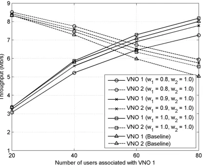
Fig. 2 illustrates the throughput performance of a two-tenant H-CRAN with different priority weighting values when
Fig. 2. Throughput performance of a two-tenant H-CRAN with dfferent priority weights.
associated with VNO 1 are admitted to the network. More importantly, the throughput performance of VNO 1 becomes lower with a lower w1 while the throughput performance of VNO 2 becomes higher1. This is because a low w1 gives a
lower probability of admitting the users associated with VNO 1, as evident in (9), and reduces the achievable throughput of VNO 1 when maximizing (10) while increasing the achievable throughput of VNO 2. Thus, the priority weight is an im-portant parameter that defines the “size” of the network slice provided to each tenant, i.e., the RRHs and the amounts of computational resources of the BBU pool, fronthaul capacity and radio resources which are allocated to each tenant. On the other hand, it can be observed that the proposed scheme with
w1 = 1.0 and w2 = 1.0 outperforms the baseline scheme, even though both schemes equally prioritize all the tenants. This thanks to Algorithm 1 in the proposed scheme, which greedily maximizes the throughput by admitting the user with the highest achievable weighted throughput. Additionally, the baseline scheme cannot differentiate the priority of the tenants, thus it will result in the same performance as in Fig. 2 regardless of the priority of the tenants.
Next, the effects of the interference constraint in (4e) to the multi-tenant H-CRAN is investigated. Fig. 3 shows the throughput performance of the two-tenant H-CRAN with different values of Imax, and w1 = 1 and w2 = 1. It can be observed that the throughput performance of the VNOs improves with a lower value of Imax as shown in Fig. 3 where the throughput gain of the network with Imax =−100 dBm over that with Imax = −90 dBm is significant. This is because the low value of Imax allows for increasing the transmission power of the RRHs on each subchannel (cf. (17)), hence the higher throughput gain. However, the throughput gain gradually reduces with an even lower Imax, as observed in Fig. 3 where the throughput gain of the network with
1Refer to (1) for the definition of the priority weighting value of a tenant.
Fig. 3. Throughput performance of a two-tenant H-CRAN with different values ofImax.
Imax =−110dBm over that withImax=−100dBm is small. This is because the allowable interference level is high enough to offset the throughput gain. Hence, the value of Imax needs to be properly tuned such that the network slice provided to each tenant can achieve optimal network performance.
V. CONCLUSION ANDFUTUREWORK
In this paper, we have proposed a new network slicing framework for multi-tenant H-CRANs. In particular, we de-fined that network slicing as a process of sharing computa-tional resources in the BBU pools, fronthaul capacity, physical RRHs and radio resources. We have formulated the framework as a weighted throughput maximization problem and solved it jointly using a greedy sub-optimal approach and a dual decomposition method. Numerical results show that the user priority weights associated with a particular tenant is a critical parameter that scales the network slice provided to the tenant. Also, the allowable interference level is another important parameter which optimizes the throughput performance of the multi-tenant H-CRANs. For future work, we will investigate the effect of the varying minimum user bit rate and fronthaul capacity to the network throughput.
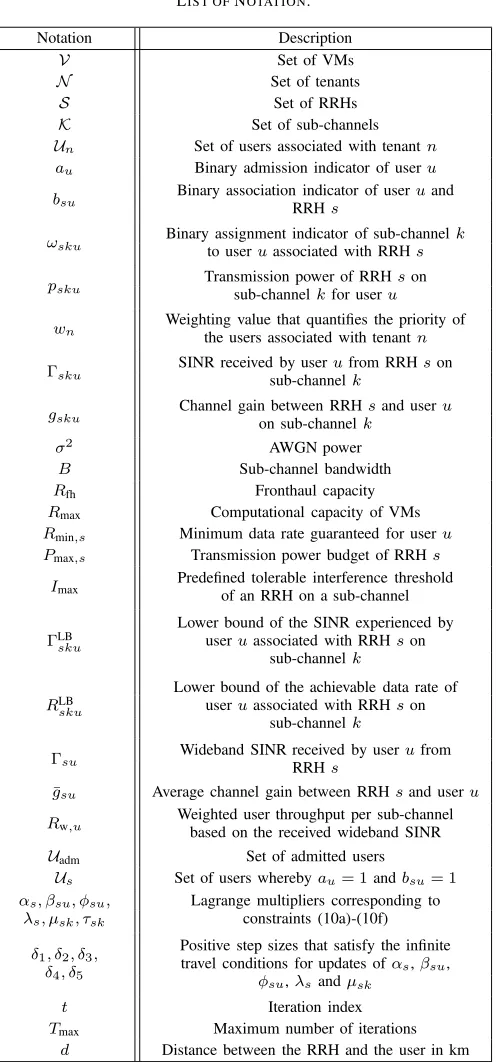
APPENDIXA LIST OFNOTATION
A list of notation used in this paper is given in Table I.
ACKNOWLEDGMENT
This work is supported in part by the Ministry of Higher Education Malaysia under the Fundamental Research Grant Scheme MMUE/140082.
REFERENCES
TABLE I LIST OFNOTATION.
Notation Description
V Set of VMs
N Set of tenants
S Set of RRHs
K Set of sub-channels Un Set of users associated with tenantn au Binary admission indicator of useru bsu Binary association indicator of userRRHs uand
ωsku Binary assignment indicator of sub-channelto useruassociated with RRHs k
psku Transmission power of RRHsub-channelkfor useruson
wn Weighting value that quantifies the priority ofthe users associated with tenantn
Γsku SINR received by userufrom RRHson sub-channelk
gsku Channel gain between RRHon sub-channelksand useru σ2
AWGN power
B Sub-channel bandwidth
Rfh Fronthaul capacity
Rmax Computational capacity of VMs
Rmin,s Minimum data rate guaranteed for useru Pmax,s Transmission power budget of RRHs
Imax Predefined tolerable interference threshold of an RRH on a sub-channel
ΓLB
sku
Lower bound of the SINR experienced by useruassociated with RRHson
sub-channelk
RLB
sku
Lower bound of the achievable data rate of useruassociated with RRHson
sub-channelk
Γsu Wideband SINR received by userufrom RRHs
¯
gsu Average channel gain between RRHsand useru Rw,u Weighted user throughput per sub-channelbased on the received wideband SINR
Uadm Set of admitted users
Us Set of users wherebyau= 1andbsu= 1 αs, βsu, φsu,
λs, µsk, τsk
Lagrange multipliers corresponding to constraints (10a)-(10f)
δ1, δ2, δ3, δ4, δ5
Positive step sizes that satisfy the infinite travel conditions for updates ofαs,βsu,
φsu,λsandµsk
t Iteration index
Tmax Maximum number of iterations
d Distance between the RRH and the user in km
[2] M. Peng, Y. Li, J. Jiang, J. Li, and C. Wang, “Heterogeneous cloud radio access networks: a new perspective for enhancing spectral and energy efficiency,”IEEE Wireless Commun. Mag., vol. 21, no. 6, pp. 126–135, Dec. 2014.
[3] F. Fu and U. C. Kozat, “Wireless network virtualization as a sequential auction game,” inProc. INFOCOM, San Diego, California, Mar. 2010, pp. 1–9.
[4] R. Kokku, R. Mahindra, H. Zhang, and R. S, “NVS: A substrate for virtualizing wireless resources in cellular networks,”IEEE/ACM Trans. Netw., vol. 20, no. 5, pp. 1333–1346, Oct. 2012.
[5] J. S. Panchal, R. D. Yates, and M. M. Buddhikot, “Mobile network
re-source sharing options: performance comparisons,”IEEE Trans. Wireless Commun., vol. 12, no. 9, pp. 4470–4482, Sep. 2013.
[6] X. Costa-Perez, J. Swetina, T. Guo, R. Mahindra, and S. Rangarajan, “Radio access network virtualization for future mobile carrier networks,” IEEE Commun. Mag., vol. 51, no. 7, pp. 27–35, Jul. 2015.
[7] C. Liang and F. R. Yu, “Wireless virtualization for next generation mobile cellular networks,”IEEE Wireless Commun. Mag., vol. 22, no. 1, pp. 61–69, Feb. 2015.
[8] P. C. Farces, X. C. Perez, K. Samdanis, and A. Branchs, “RMSC: a Cell slicing controller for virtualized multi-tenant mobile networks,” inProc. IEEE 81st VTC Spring, Glasgow, United Kingdom, May 2015, pp. 1–6. [9] G. Tseliou, F. Adelantado, and C. Verikoukis, “Scalable RAN virtualiza-tion in multi-tenant LTE-A heterogeneous networks,”IEEE Trans. Veh. Technol., pp. 1–14, Sep. 2015, in press.
[10] S. Khatibi and L. M. Carreia, “A model for virtual radio resource management in virtual RANs,” EURASIP J. Wireless Commun. Netw., vol. 2015, no. 68, pp. 1–12, Mar. 2015.
[11] W. Yu and R. Lui, “Dual Methods for nonconvex spectrum optimization of multicarrier systems,”IEEE Trans. Commun., vol. 54, no. 7, pp. 1310– 1322, Jul. 2006.
[12] S. Boyd and L. Vandenberghe, Convex optimization. Cambridge University Press, 2004.
[13] K. Kim, Y. Han, and S.-L. Kim, “Joint subcarrier and power allocation in uplink OFDMA systems,” IEEE Commun. Lett., vol. 9, no. 6, pp. 526–528, Jun. 2005.
[14] S. Boyd, L. Xiao, and A. Mutapcic, “Subgradient methods,” Notes for EE364b, Stanford University, 2006-07.
[15] “Technical specification group radio access network; evolved universal terrestrial radio access (E-UTRA); physical channels and modulation,” TS 36.211, 3rd Generation Partnership Project (3GPP), Sophia-Antipolis, France, Sep. 2015. [Online]. Available: http://www.3gpp.org/DynaReport/36.211.htm