SIZE REDUCED DUAL FREQUENCY
PATCH ANTENNA FOR WIRELESS
APPLICATIONS
P.A.AMBRESH*, P.M.HADALGI, P.V.HUNAGUND
*
Microwave Laboratory, Department of P.G. Studies & Research in Applied Electronics, Gulbarga University, Gulbarga-585106. Karnataka, (INDIA).
Abstract:
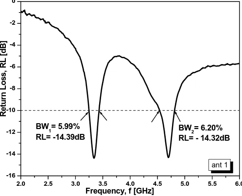
A novel design technique of patch antenna is proposed and experimentally studied. By etching unequal shaped slot structure on conducting patch element, the resonant frequency of the proposed antenna is significantly lowered compared to designed frequency, leads to size reduction of patch antenna (25 % size reduction) at resonant frequency. Proposed antenna is designed and fabricated on a FR4 superstrate with a thickness of 1.66 mm. Experimental results show that an acceptable impedance bandwidth of 200 MHz ((5.99 %) at 3.34 GHz) and 290 MHz ((6.20 %) at 4.70 GHz) are obtained. The maximum peak gain of 4.85 dB and 5.94 dB at two
resonant frequencies with 3-dB half power beamwidth (HPBW) of 34o, 43o are also obtained. Measured results
also show that proposed antenna achieved broadsided radiation pattern with linear polarization characteristics. The results show that the resonant frequencies are used in wireless communication applications namely, WiMax, maritime mobile services, RADAR communication, fixed satellite services.
Keywords: Size reduction; rectangular patch; radiation pattern; superstrate; RADAR; Wireless communication application.
1. Introduction
Microstrip antennas are the most rapidly emerging area in the antenna field in the most recent years due to their light weight, low volume, thin profile configuration and low fabrication cost. Because of these advantages they are extensively used in the communication systems such as personal communication systems, mobile satellite communications, wireless communication systems, direct broadcast television, wireless local area networks etc.. On the other hand, MSAs suffer from very narrow impedance bandwidth (1-2%) with respect to center frequency. This poses a design challenge for the antenna designer to meet size reduction with acceptable bandwidth and gain characteristics. The present trend of wireless application system also needs to have multiple functionality that presents challenges to have dual-frequency antenna in a simple manner. There are several methods to obtain dual frequency, size reduction with improvement in bandwidth and gain by the use of thick substrate, cutting a resonant slot inside the patch, the use of a low dielectric substrate, multi- resonator stack configurations, the use of various impedance matching and feeding techniques, and the use of slot antenna geometry [1, 2, 3, 4 and 5]. Proposed design uses probe feeding method with slot on the patch to improve the different parameters of microstrip antenna.
Ravi.Y.M. et.al.[6] studied the stacked rectangular microstrip antenna (SRMSA) using a co-axial probe feed
method achieved 23.6 % of size reduction by embedding a pair of T-slots either in the lower patch, upper patch or on both patches with a bandwidth of 1.63 % by embedded T-slots in the lower patch of the SRMSA. Stacked configuration also increases the weight of the antenna which is again undesirable in wireless environment.
Recently, Abdelaziz A et.al.[7] designed a circularly polarized shorted Rectangular Microstrip Patch Antenna fed
through co-axial probe with shorting wall and small perturbed area on the patch is designed and fabricated, attained 24.6 % reduction in size. In this paper, an attempt has been made to reduce the size of microstrip antenna, with improved bandwidth, gain without any complexity in design by using inverted patch configuration, with air substrate and inclusion of unequal shaped slots placed on the patch surface, achieved 25 % of size reduction with the improvement in impedance bandwidth characteristics upto 290 MHz has dual frequency functionality.
2. Patch Antenna Design
configurations. The inverted rectangular patch, with dimension of length and width, L (o/4.39), W (0.299o)
where, ois operating wavelength and is supported by superstrate FR4 with dielectric permittivity Єr(4.4)and
thickness h (1.66 mm). An air-filled dielectric with dielectric constant Єo= 1 with thickness Δ (8.5mm) is
sandwiched between the superstrate and ground plane. The patch and the ground plane were practically fastened together by plastic spacers along the corners of the patch antenna as shown in Fig. 1(a).
Unequal shaped slots are added on the patch as shown in Fig. 1(b), where Ls1= 17.14 mm, Ls2= 2.1 mm , Ls3=
19.14 mm and Ws1 = 2.68 mm,Ws2= 6.51 mm,Ws3= 4.86 mm are the slot lengths and widths with spacing
maintained between slots as indicated by S1= 5.17 mm, S2= 2.01 mm, S3= 1.01mm, S4= 4.17 mm, S5= 1.86 mm,
S6= 9.2 mm, S7= 0.68 mm. Slot lengths, widths and spacing dimensions are functions of operating wavelength
o. The patch is excited by a co-axial probe along the Y-axis at a distance fp = 4.3 mmfrom the top edge of the patch as shown in Fig. 1(a). The location of the feed point on the patch is critical for the proper impedance matching and to have better return loss characteristics and is optimized based on the mathematical equations mentioned in [8].
Ground plane used in the design is an aluminium plate with dimensions of 35 mm X 35 mm with thickness h1
(1mm). The use of probe feeding technique, slots on the patch with thick air filled substrate provide reduced size of the patch with improvement in impedance bandwidth while inverted radiating patch and the use of parallel slots also offered gain enhancement and provides the necessary protection for the patch from environmental effects. Patch comprising slots are being placed symmetrically near the excitation probe and defines a capacitive load for compensating an inductance of the excitation probe pin so as to obtain good impedance matching
characteristics [9]. Adding two or more slots on the patch eventually improves the overall impedance bandwidth
and also achieves size reduction. The presence of multiple-slots restricts the patch currents, at its resonance
frequencies that will provide lower resonant frequency with lower return loss [10].
(a)
(b)
2.0 2.5 3.0 3.5 4.0 4.5 5.0 5.5 6.0 -16 -14 -12 -10 -8 -6 -4 -2 0 BW 2= 6.20% RL= - 14.32dB BW
1= 5.99% RL= -14.39dB R e tu rn L o s s , RL [ d B]
Frequency, f [GHz]
ant 1 0 30 60 90 120 150 180 0dB -20 -10
ant 1 (at 3.34 GHz) : Co-polar Cross-polar
3. Experimental Description
The resonant properties of the proposed antenna have been experimentally tested on Vector Network Analyzer (Rohde and Schwarz, Germany make ZVK model 1127.8651). Fig. 2 illustrates the measured result of the return loss (RL) versus frequency for proposed patch antenna wherein, it is observed that two distinct operating frequencies are excited which will result in dual frequency functionality. Here, the slot on the patch creates first lower resonance frequency at 3.34 GHz and second resonance at 4.70 GHz which offered 25 % size reduction. The improvement in bandwidth upto 200 MHz (5.9 %) is achieved at 10dB return loss (for VSWR<1.5) covering 3.24 – 3.44 GHz band and second resonant frequency achieved bandwidth of 290 MHz (6.20 %) covering 4.53 – 4.82 GHz band and attained gain of 4.85 dB and 5.94 dB respectively. Fig. 3 shows the measured radiation patterns of the proposed patch with co-polar and cross-polar characteristics. The radiation patterns are measured and plotted at respective resonant frequencies 3.22 GHz and 4.70 GHz. As shown in Fig. 3, the antenna exhibits good broadband radiation patterns with linear polarization characteristics. It is also noted that 3dB beamwidth (HPBW) are 34o, 43o respectively.
0 30 60
90
120
150
180
0dB
-20 -10
ant1 (at 4.70 GHz) : Co-polar Cross-polar
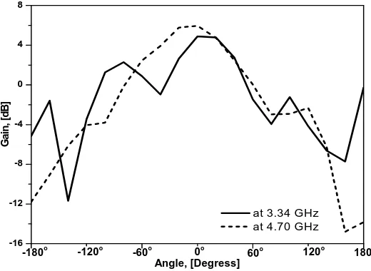
Plot of gain response against various rotational angle of the proposed antenna is as shown in Fig. 4 and is seen that maximum peak gain of 5.94 dB is achieved.
-16 -12 -8 -4 0 4 8
at 3.34 GHz at 4.70 GHz
-180o -120o -60o
180 120o 60o
0o
G
a
in
, [d
B
]
Angle, [Degress]
Fig. 4. Measured Gain response curve of proposed antenna
Fig. 5 shows Smith chart plot of impedance locus versus frequency for the proposed antenna confirming that presence of two loops on the Smith chart proves dual frequency with better impedance matching characteristics between the input and the load.
Fig. 5 Measured input impedance characteristics on Smith chart
Fig. 6 depicts the VSWR characteristics and is obviously confirmed that the measured impedance bandwidth, return loss parameters are considered for VSWR < 1.5.
Fig. 6 Measured VSWR Vs frequency characteristics of proposed antenna
4. Conclusion
Acknowledgment
The authors would like to convey thanks to the Department of Science and Technology (DST), Government of India, New Delhi, for sanctioning Vector Network Analyzer to this Department under FIST Project and also providing financial assistance under Rajiv Gandhi National fellowship [No.F.14-2(SC)/2009(SA-III) dated 18 November 2010] scheme by University Grants Commission, New Delhi, India.
5. References
[1] Zhang, Y. P. and J. J. Wang. (2006): “Theory and analysis of differentially-driven microstrip antennas,” IEEE Trans. Antennas Propag., 54, pp. 1092-1099.
[2] Pozar, D. M. and D. H. Schaubert Microstrip Antennas. (1995): TheAnalysis and Design of Microstrip Antennas and Arrays, IEEE Press, New York.
[3] Matin, M. M.; B. S. Sharif; and C. C. Tsimenidis. (2007): “Probe fed stacked patch antenna for wideband applications,” IEEE Trans. Antennas Propag. 55(8), pp. 2385- 2388.
[4] Wi, S. H.; Y. B. Sun; I. S. Song; S. H. Choa; I. S. Koh; Y. S. Lee and J. G. Yook. (2006): “Package-Level integrated antennas based on LTCC technology,” IEEE Trans. Antennas Propag., 54(8), pp. 2190-2197.
[5] Wi, S. H.; J. M. Kim; T. H. Yoo; H. J. Lee; J. Y. Park; J. G. Yook; and H. K. Park. (2002): “Bow-tie-shaped meander slot antenna for 5 GHz application,” Proc. IEEE Int. Symp. Antenna Propag., 2, pp. 456-459.
[6] Ravi M Y; Vani R M; P V Hunagund. (2009): “A comparative study of compact stacked rectangular microstrip antennas using a pair of T-shaped slot,” Icfai Journal of Science & Technology, 5(1), pp.58-66.
[7] Abdelaziz A.; Abdelaziz Dalia; M. Nashaat. (2008) “Compact GPS microstrip patch antenna,” Journal of Theoretical and Applied Information Technology, 4(6), pp.530-535.
[8] Kara, M.(1996): “The Resonant frequency of Rectangular Microstrip Antenna Elements with various substrate thickness”, Microwave opt. Technical lett., 12, , pp.234 – 239.
[9] M.T.Islam; M.N.Shakib; N.Misran. (2009):“Design Analysis of High gain wideband L-probe fed microstrip patch antenna”Progress In Electromagnetics Research, 95, pp.397-407.