INFINITELY VARIABLE
TRANSMISSION USING FOUR BAR
MECHANISM
Dr.N. ARUNKUMAR1
1
Professor, Department of Mechanical Engineering, St. Joseph’s College of Engineering, Old Mahabalipuram Road,
Chennai,Tamil Nadu-600119, India. [email protected]
R. SANTHOSH2
2
Graduate, Department of Mechanical Engineering, St. Joseph’s College of Engineering, Old Mahabalipuram Road,
Chennai, Tamil Nadu-600119, India. [email protected]
S. SUNIL SUBRAMANIAM3
3
Graduate, Department of Mechanical Engineering, St. Joseph’s College of Engineering, Old Mahabalipuram Road,
Chennai, Tamil Nadu-600119, India. [email protected]
ABSTRACT
Most of the continuously variable transmission systems in automobiles now-a-days are non-positive drives. This means that they cannot be used in heavy vehicles that require very high torque to be transmitted. This new type of infinitely variable transmission is aimed at transmitting high torques by making it a positive drive, thus making continuously variable transmission systems to be suitable for heavy vehicles. Infinitely variable transmission system and continuously variable transmission system are both the same except that there is an extra zero gear ratio in infinitely variable transmission system. This newly developed transmission system is basically a four bar mechanism with variable crank radius which makes it possible to have continuously variable mechanical advantage. The output lever which oscillates in the four bar mechanism is connected to a ratchet mechanism which turns the output shaft intermittently, two four bar mechanisms with a phase difference of 180 degrees is used to avoid the intermittent rotation of the output shaft. A flywheel is used in the output shaft to reduce the fluctuations in both speed and torque.
Keywords- Continuously variable transmission (CVT), Infinitely Variable Transmission (IVT), four bar mechanism, angular velocity ratio theorem, mechanical advantage, Positive drive.
1. Introduction
The continuously variable transmissions used now- a-days in two wheelers (scooters) consists of a belt drive with variable diameter pulley. This works very well for two wheelers, since it requires only less torque to be transmitted. But it cannot be used for heavy duty vehicles, since the belt will start to slip at higher torques. It is not used in cars for the same reason. For this reason, an infinitely variable transmission has been developed which does not have non-positive drives. The drive is also smooth because there is no need for changing gears manually. The manufacturing cost is also reduced with this design. The cost is reduced since the components used are relatively simple to manufacture. It can be easily automated. This type of transmission does not need much maintenance because of the reduced number of components compared to the other types of automobile transmission.
Many types of continuously variable transmissions have been developed, but most of the commercially available continuously variable transmission systems are non-positive drives. Most of them are continuously variable type which means that they cannot be brought to neutral or zero gear ratio. But this type of infinitely variable transmission with easier control on gear ratios could be very useful for automobiles. The output shaft from the transmission is driven by a ratchet because of which the torque cannot be transmitted in the reverse direction i.e. from the vehicle’s wheel to the engine; this is a very big advantage as it is very comfortable to the passengers in the vehicle (the dragging feeling is not felt when the driver releases the throttle pedal).
2. Components
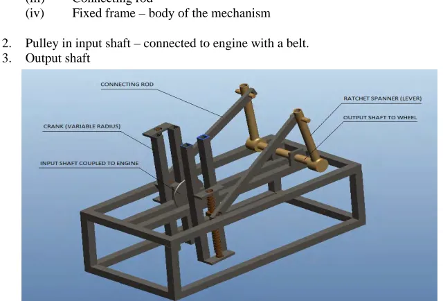
A four mechanism consists of four links, three moving links with one fixed link. The components involved in this design are shown in fig. 2.1.
The components in this transmission system are:
1. Four bar mechanism – two numbers (with phase difference of π radians) (i) Crank – variable radius (lead screw mechanism)
(ii) Lever – connected to output shaft with ratchet mechanism (iii) Connecting rod
(iv) Fixed frame – body of the mechanism
2. Pulley in input shaft – connected to engine with a belt. 3. Output shaft
Fig. 2.1 CAD model of the transmission system.
3. Working
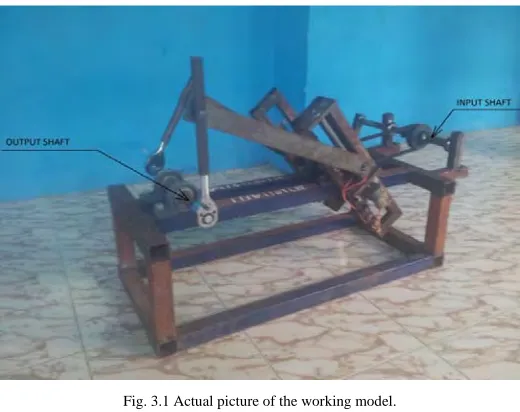
Fig. 3.1 Actual picture of the working model.
The working model shown in fig. 3.1 is driven manually for testing purposes. The actual transmission system will have the input shaft connected to the engine crank shaft. When the crank rotates, the lever oscillates causing the ratchet mechanism to turn the output shaft intermittently.This intermittent motion is avoided by using two four bar mechanisms which have a phase difference of π radians. Therefore when one of the levers is in its idle stroke the other lever is in its driving stroke. This leads to the continuous smooth motion of the output shaft. In the working model a ratchet spanner has been used as a lever which serves as a ratchet mechanism as well. The working model shown in fig. 3.1 has a variable crank length of 0 to 200 mm, connecting rod of length 400 mm, lever of length 200 mm, and a fixed link length of 400 mm.
4. RESULTS AND DISCUSSION
The evaluation of the performance of this transmission system is carried out based on the output torque vs. crank or input shaft angle diagram. This diagram is used particularly because of the four bar linkage used in this system. The four bar linkages are characterised by an important parameter called the transmission angle [1]. Since the transmission angle varies continuously when the transmission system is operating, the output torque transmitted by the system also fluctuates. The transmission angle is one of the indices of merit of the linkage. John Joseph Uicker et al. [1] suggests that a mechanism should have transmission angle of about 90° for maximum efficiency and superior mechanical advantage [1]. The theoretical analysis on the torque vs. crank angle relation will be derived in the following discussions for this transmission system.
4.1 Theoretical output torque vs. crank angle relation
The distanc AB CB Using the every valu satisfied, s Using the triangle OB
OB O
Using the l
Φ cos
The force a
F I
The force d to get the c
F F
The sum o following e
γ 360
The output
F F
The output
Output tor
ce between the
B cos θ
above equation e of θ. The com ince the length
value of θ' ob BC.
OC BC
length of diago
OA AB O AB OA acting on the c
OA due to the torq component of f
cos 90 Φ
of angles insid equation,
180 θ
t force acting o
cos 90 γ
t torque is give
rque F le
e points A and
OC OA c
n the value of mputer program hs of all the link
btained above,
2 OC BC
onal OB, the co
B
rank is given b
que applied on t force that is act
de a quadrilate
Φ θ on the lever is g
en by,
enth of lever
Fig. 4.1 fou
B is given by,
cos θ C
θ' is found by m substitutes d ks are known.
the length of
cos 180 θ
osine law is app
by,
the input shaft ting on the con
eral is 360 deg
given by,
BC
ur bar mechanism
CB sin θ
y trial and error different values
the diagonal O
θ plied to the tria
t is perpendicul nnecting rod.
grees, so the tr
OA sin θ
r in Microsoft s of θ’ in the a
OB is found by
angle OAB to
lar to the crank
ransmission an
Visual Basic 2 above equation
y using the co
find the value
k, this force sh
ngle γ can be
Eq. (1)
2010 express f till the equatio
osine law for th
Eq. (2)
of Φ.
Eq. (3)
Eq. (4)
ould be resolve
Eq. (5)
found using th
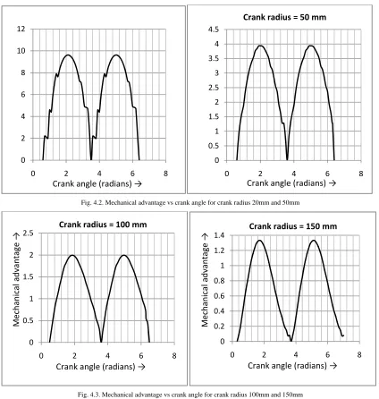
The mechanical advantage changes for different values of crank angle, so the entire calculation is done for every crank angle from 0 to 6.28 radians in Microsoft Visual Basic 2010 express and they are plotted.
The various plots of mechanical advantage (gear ratio) vs. crank angle for different crank radius are shown below,
Fig. 4.2. Mechanical advantage vs crank angle for crank radius 20mm and 50mm
Fig. 4.3. Mechanical advantage vs crank angle for crank radius 100mm and 150mm
From the above plots it is observed that the mechanical advantage is higher for smaller crank radius and decreases as the crank radius is increased. And the momentary lag of one four bar mechanism is compensated by the other which is operating with 180° phase difference. Thus a continuous rotation is obtained at the output shaft. To have a constant torque output a flywheel is used, from which the output is transmitted to the wheels. Thus the fluctuations in the mechanical advantage vs. crank angle diagrams shown in fig 4.2 and fig 4.3 are reduced using a flywheel; therefore the output shaft will have a constant mechanical advantage for all crank angles as shown in fig 4.4.
Mechanical advantage→
Crank radius = 20 mm
Mechanical advantage →
0 2 4 6 8 10 12
0 2 4 6 8
Crank angle (radians) →
0 0.5 1 1.5 2 2.5 3 3.5 4 4.5
0 2 4 6 8
Crank radius = 50 mm
Crank angle (radians) →
0 0.5 1 1.5 2 2.5
0 2 4 6 8
Crank radius = 100 mm
Me
ch
an
ic
al
ad
van
ta
ge
→
Crank angle (radians) →
0 0.2 0.4 0.6 0.8 1 1.2 1.4
0 2 4 6 8
Crank radius = 150 mm
Crank angle (radians) →
M
ec
h
an
ic
al
ad
van
tage
Fig. 4.4 Mechanical advantage vs. crank angle with flywheel for crank radius 20 mm.
0 1 2 3 4 5 6 7 8 9 10
0 2 4 6
Crank angle (radians) →
Me
ch
an
ic
al
ad
van
tage
→
Crank radius = 20 mm
0 0.5 1 1.5 2 2.5
0 2 4 6
crank
angle
vs.
lever
angle(
θ
'),
crank
radius
=
100
mm
Le
ver
an
gle
(radians)
→
Crank angle (radians) →
0 0.5 1 1.5 2 2.5
0 2 4 6
crank
angle
vs.
lever
angle(
θ
'),
crank
radius
=
50
mm
Le
ver
an
gl
e(rad
ia
ns
)
→
Crank angle (radians)→
0.5 1 1.5 2 2.5 3
crank
angle
vs.
lever
angle(
θ
'),
crank
radius
=
150
mm
an
gle(r
ad
ia
ns
)
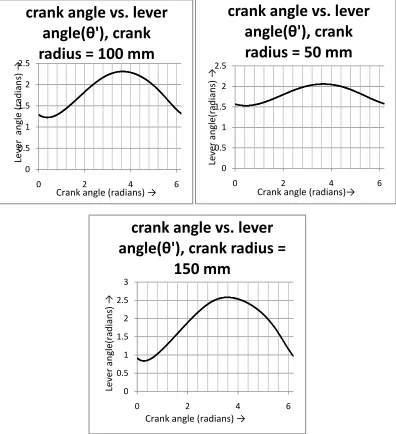
The plot shown in fig 4.5 is based on the calculations in section 4.1 and the values have been generated by using a simple computer model programmed in visual basic 2010 express, the calculations have been programmed in the computer model. It is obvious from the plots in fig 4.5 that the lever stroke angle (difference between the maximum and minimum lever angles) is directly proportional to the crank radius and thus the speed ratio is directly proportional to the crank radius.
5. CONCLUSION AND SCOPES IN FUTURE
Infinitely variable transmission system can be an effective replacement for the conventional continuously variable mechanism .This can be used in heavy vehicles, SUVs etc., and the maintenance of this mechanism is easier compared to the conventional continuously variable transmission (CVT). The construction is also very simple compared to continuously variable transmission (CVT).There are several other types of infinitely variable transmission, but most of them are non- positive type, but thistype of transmission is positive type so it can be used for higher torque transmission. It is also suitable for buses and military vehicles, so it reduces the effort made by the driver. It also reduces driver’s effort in shifting gears which increases his concentration on the road. This type of transmission can also provide rapid acceleration and deceleration of the vehicle. This type of transmission also has lesser moving parts which considerably reduces the frequency of maintenance. One of the main advantage is that, clutch is not required in this type of transmission.It is the most fuel efficient transmission since it can be in neutral (engine turns but power not transmitted like bicycle) when the vehicle is moving in inertia force.
REFERENCES
[1] Aaron Kuchle, HaraldNaunheimer, Bernd Bertsche, Joachim Ryborz, Wolfgang Novak and Peter Fietkau, Automotive Transmissions: Fundamentals, Selection, Design and Application, Springer (2010).
[2] Ferdinand Beer, Jr. Johnston and Russell, E; Phillip Cornwell, Vector Mechanics for Engineers: Statics and Dynamics (10th
edition), McGraw-Hill Education, 2012.
[3] Flores, P;Ambro´sio, P; Claro, J.C.P;Lankarani, H.M;Koshy, C.S, “A study on dynamics of mechanical systems including joints with clearance and lubrication,” Mechanism and Machine Theory, vol. 41, pp. 247-261, 2006.
[4] George B. Thomas and Ross L. Finney, Calculus and Analytic Geometry, Addison Wesley, 9th
edition ISBN-10: 0201531747 (August 14, 1995).
[5] Hee-Duk Yoon, Evaluation of a Continuously Variable Transmission Utilizing Non-circular Gears, University of Wisconsin-Madison (1995).
[6] Jack A. Collin; Henry R. Busby and George H. Staab,Mechanical Design of Machine Elements and Machines, ISBN: 0470413034, 9780470413036, John Wiley & Sons (2010).
[7] John Joseph Uicker, Pennock, G.R; Joseph Edward Shigley ,Theory of machines and mechanisms, McGraw-Hill series in mechanical engineering, Oxford University Press (2003).
[8] John R. Maten and Bruce D. Anderson, Continuously Variable Transmission (CVT), PT - Society of Automotive Engineers vol-125(2006).
[9] Rhee, J; Akay, A, “Dynamic response of a revolute joint with clearance”, Mechanism and Machine Theory, vol. 31, pp. 121-134, 1996.
[10] Sandgren, E;Ragsdell, K. M, Optimal Flywheel Design with a General Thickness Form Representation, J. Mech. Des. 105(3), pp. 425-433 (Sep 01, 1983).
[11] Wilson, Kinematics And Dynamics Of Machinery 3/E, Pearson Education India (2008) ISBN: 8131720225, 9788131720226. [12] Yu, S.D; Cleghorn, W.L, “Dynamic instability analysis of high-speed flexible four-bar mechanisms,” Mechanism and Machine