PREDICTION OF PERFORMANCE OF
HIGH PERFORMANCE FIBER
REINFORCED CONCRETE
BEAM-COLUMN ASSEMBLIES
RAJESH KUMAR SHARMA
Research Scholar, Civil Engineering Department, National Institute of Technology, Kurukshetra Kurukshetra, Haryana-136119, India
H.K.SHARMA
Professor, Civil Engineering Department, National Institute of Technology, Kurukshetra Kurukshetra, Haryana-136119, India
Abstract The performance of the beam-column assemblies was demonstrated as an important factor in the overall behavior of joints subjected to lateral loads. Cyclic loads in beam & column assembly during an earthquake can cause distress and even failure when design is not proper and joint is not properly detailed. The use of high performance reinforced concrete (HPFRC) is highly desirable to withstand seismic loads on structures. In the present study, finite element analysis of two types of external beam-column assembly is done using ANSYS v15. 0. The first type of beam-beam-column assembly is non-fibrous and the second types of beam-column assemblies are with different volumes of fibers, fiber types and aspect ratios. The load deflection behavior, strain-strain characteristics, failure characteristics, strength characteristics and parameters associated with ductility and degradation of stiffness were studied. Maximum load capacity, moment of resistance, energy absorption capacity, ductility and toughness were found to corresponding to an optimum crimped fiber content of 9 percent with the aspect ratio 80 in column assembly with HPFRC subjected to cyclic loading. The application of HPFRC in beam-column joint, therefore decrease rate of degradation of stiffness but improves dimensional stability, strength and integrity of joint.
Keywords: Beam-Column Assemblies, Failure Characteristics, High Performance Fiber Reinforced Concrete (HPFRC), Stiffness Degradation, Envelope Curves.
1. Introduction
The design of the beam-column assembly mainly focuses on the shear strength of the assembly and sufficient anchorage in the assembly. In a time-resistant frame, column-beam junctions are normally classified according to their corner configuration, both indoors and outdoors. A number of national and international codal provisions have been periodically revised to incorporate existing research in practice as it has been recognized that beam-column assemblies are the critical areas in reinforced concrete frames designed for an inelastic response under seismic conditions. The essential requirements of design of assembly is that the assembly must be strong than the connecting column or beam. The design and detailing provisions of current seismic codes IS: 13920 and IS: 1893 are not found adequate to ensure ductile failure because of shear forces developed in the assembly during severe seismic attacks. The current codes therefore have been upgraded recently to incorporate shear design provisions for beam-column assemblies.
properties. The well-established fact that the FRC's application can effectively improve the performance of beam-column assemblies, resulting in increased load capacity and better deformation capabilities before the diagonal crack formation can be used in the region of the articular nucleus. Experimental studies [1] and [2] have predicted that seismic performance in terms of critical shear elements, i.e. beam-column assemblies, squat walls, coupling beams and bending elements subjected to high shear stresses, can be obtained using FRC. However, because of the limited volume of fibers, FRC did not show significant improvement in strength, although the toughness was significantly improved. Higher fiber volume was therefore considered necessary to improve concrete strength [3]. This lead to development of another next-generation material, called Slurry-Infiltrated Fibrous Concrete (SIFCON).
SIFCON is an upgraded version of conventional FRC. It is a high performance concrete with unique properties in the field of strength and ductility. SIFCON is similar to FRC in the sense that it has discrete locking fibers that provide significant tensile properties of the composite matrix. The fiber content in FRC generally ranges from 1 percent to 3 percent by volume, while in SIFCON, the fiber content ranges from 4 percent to 20 percent. The process of manufacturing SIFCON is also different because of the high fiber content. SIFCON is cast using a technique in which the steel fibers are placed in the mold at full capacity and infiltrated with cement-based sludge [4].
Examination of existing published literature indicated that the addition of fibers in the joint region improves the overall behavior of the joint. Farhan et al..[5], developed a numerical model based on the finite element method using ANSYS. The study showed that a joint is not rigid because it undergoes deformations at all stages of loading. The authors have suggested that straight and hooked steel fibers can be used in construction, with the hooked steel fiber being more advantageous. Uma et al. [6] and [7], reviewed design codes for three countries, ACI 318M-02, NZS 3101: 1995 and EN 1998-1; 2003. The authors noted that the three codes were designed to meet the requirements for joint and shear in the joint. The column depth required by ACI was smaller than that given by the other codes depending on the anchoring conditions. The NZS and EN codes considered the level of shear to obtain the required shear stirrups while the ACI provided stirrups reinforcement to retain the axial load capacity of the column by confinement. The variation in the shear strength requirement was found to be substantial among the three codes. Shaikh et al. [8], performed a finite element modeling of two types of outer beam column joints using ANSYS. The first specimen has been detailed according to IS13920: 1993 and the second has been detailed with additional diagonal cross-bars. The specimens were subjected to cyclic loading. All samples failed to develop tensile stresses at the boundary of the beam-column. Patil, et al. [9], carried out a numerical study using ANSYS on the exterior and corner beam column joints under a quasi-static loading on the cantilevered end of the beam. The results indicated lower values of maximum stresses and deflection under fixed support conditions relative to a hinged connection. The stiffness of the structure had the most profound effect on displacement, maximum and minimum stresses.
Abbas et al. [10], studied the numerical behavior of steel reinforced concrete in the outer and inner assemblies under seismic action under constant axial load due to the application of cyclic loading using the ABAQUS software. The results showed that the addition of steel fibers improved the strength constantly as their amount was increased. The addition of fibers also led to an improvement in ductility compared to the control sample. The addition of fibers could also allow sufficient confinement when the transverse reinforcement is reduced or eliminated. Kulkarni et al. [11], modeled exterior beam-column joints with additional inclined transverse bars in the column using ANSYS. The joints with additional reinforcement bars showed no appreciable deterioration even after reaching their final capacity. The transverse inclined bars in the column deterioration even after reaching its final capacity increased the shear strength of the joint according to the aspect ratio of the joint. Kiran et al. [12], used a micro-plane analysis program (MASA) to perform a nonlinear analysis of three exterior joints designed according to the old ACI, Japanese and Indian practices for the outer joints of the beam-columns. It was found that the anchor configuration had a significant impact on the load bearing capacity and the failure mode of the outer beam- column joints. Roehm et al. [13], studied the performance of reinforced concrete and reinforced concrete beam (SFRC) columns under cyclic loading, the results showed the possibility to predict the load deflection curves and the damage model of the test pieces before the test. The authors found that the failure mode could not only be modified with fibers if the concrete strength was too low. Lobo et al. [14], proposed a numerically effective approach to describe the bond slip in the conjugate core of the inner joints of the beam-columns. Bond-Slip influences the stiffness and the energy-distributing capacity of the joint. The authors found that with the introduction of a fiber model based on continuous anchored bars, the cost of calculating the analysis was increased and this was supplemented by an increase in the accuracy of the results by the introduction of the bond sliding characteristics in the joint core.
The aim of this study is to better understand the behavior of the beam-column assembly of high performance reinforced concrete (HPFRC) with SIFCON in the joint core during positive cyclic loading with respect to load capacity, deformation behavior, energy absorption capacity, stiffness degradation and stress-strain behavior. The nonlinear finite element model is also developed with ANSYS software to validate the experimental results with respect to load response behavior, stress-strain characteristics and similar failure modes.
High performance fiber reinforced concrete (HPFRC) in SIFCON form has improved thermal properties, fire resistance and reduced autogenous shrinkage. It also has excellent freezing and thawing resistance, less flexibility due to micro-cracks, fire resistance and better sound absorption. In addition to its improved structural properties, SIFCON has lower cracking aggregates reduces dead loads by approximately 25-35% over conventional concrete, which offers significant cost savings by providing less dead loads, improved seismic response, longer span, thinner sections, less reinforced concrete and and better slip resistance and is easy to place in the concrete pumping process. The use of SIFCON light weight lower first cost, reduced transport and placement costs further make the material most versatile in its applications.
Strain-stress characteristics of the fiber-reinforced cement-based matrices are distinguished by their post cracking strain behavior. Fragile matrices lose their tensile strength immediately just after the formation of the first crack, Fig. 1 [20]. The addition of FRC adds toughness, but their tensile strength, and in particular the strain capacity, does not improve considerably after the first cracking. The SIFCON is merely considered as a quasi-fragile material with tension softening deformation behavior, i.e. delay in loading immediately after the localization of the composite deformation by a first cracking. In the present study, analytical investigations are conducted to study the behavior of FRC based beam column joints, using standard software ANSYS, which is capable of performing simple, linear, static, nonlinear and transient analysis for high performance fibrous beam column joints.
Fig. 1 Schematic stress-strain behavior of cementitious matrices in tension [20]
Finite Element Method (FEM) is an analytical procedure whose active development has continued over a relatively short period of time. The basic concept of the method applied to the problem of structural analysis is that the total structure can be analyzed analytically by dividing into its domains (finite elements), each of which describes a distinct set of presumed functions representing stresses & displacements in this region. These finite elements are not simply coupled to some node-specific points, but some constraints are imposed on the element's basic variables to give a continuous effect.
FEM provides a powerful and general tool for studying behavior of beam-column assemblies. ANSYS, which is a Finite Element based analyzing tool, is capable of solving critical nonlinear problems. In recent years, fibrous reinforced composites have made significant progress in this direction due to technical development and, on the other hand, a better understanding of the basic mechanism for structural behavior.
The basic principle of analysis using FEM is that the body or structure is divided into smaller finite elements, called "finite elements". The original structure is then considered the configuration of these elements as the final number of joints in the set. The properties of the elements are formulated and combined to provide a complete design solution. The shape functions are chosen approximately to move the variation in the element relative to the displacement in the element nodes. The strains and stresses in the elements are evaluated with respect to displacement of the node. The principle of virtual displacements is used for deriving the equations of equilibrium and node transitions are unknown in the equations.
2. Formulation of Problem
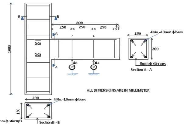
Fig. 2 Beam-column assembly illustrating reinforcement detailing
3. Modeling in ANSYS
.Modeling requires the creation of geometry of the whole structure by incorporating elements representing structural behavoiur, including the boundary conditions of the problem under consideration, properties of the material and the loads on various elements and their combinations. The ANSYS post-processing is used to analyze the results of the solution obtained. A general post-processing agent is used to obtain plotting details pertaining to deformation, stress and strain values, etc. and to analyze and interpret the results. In the present study ANSYS v15.0 is used to predict load deflection behaviour, stress-strain characteristics, failure behaviour and ductility associated parameters, etc. during the course of cyclic loading in beam column joint region, considering appropriate elements, geometry and material models..The input data required to concrete and steel in ANSYS V15.0 are presented in Table 1. Where in NFC/0 denotes Non Fiber concrete, SF 40/6 denotes Straight Fiber of 40 mm length and 6 percent fiber volume, similarly ZZ 40/6 denotes Crimped ( Zig Zag) Fiber of 40 mm length and 6 percent fiber volume.
Table 1 Input data required for concrete and steel in ANSYS V15.0
S.
No. Concrete Steel
1 Elastic Modulus (Fig. 3) Elastic Modulus=200000 N/mm2
2 Poisson ratio = 0.18 and 0.20 Poisson’s Ratio = 0.30
3 Stress Strain Curve Under Compression (Fig. 3) Yield Stress = 415 N/mm2
4 Ultimate Uni-axial Tensile Strength: (Fig. 4) Tangent Modulus =30.8 N/mm2
Fig. 4. Stress Strain Curve for Concrete Under Tension
Fig. 3 and 4 illustrate stress- strain behaviour under compression and tension, respectively, for normal and HPFRC with fiber contents ( Vf ) varying from 0, 6, 8, 9 & 10 percent and aspect ratio(µ) , 80 and 100 using
straight and Zig –Zag(crimped) shape fibers.
In the beam-column assembly, concrete was modeled using a special element in special packaging, SOLID 65 elements, whereas reinforcement modeling was done using the LINK 180 element as shown in Fig. 5(a). SOLID 65 elements are used to model elements of reinforced concrete or reinforced composite materials, such as fiber. This element comprises eight nodes, each node having three degrees of freedom of translation in the nodal directions X, Y and Z. The element can be used to analyze tensile cracking and compression crushing. The element itself is used to analyze problems with or without reinforcement bars.
Fig. 5(a) Solid 65 elements Fig.5 (b) Link 180 Element
LINK 180 is a spar element / elongated beam, used in various engineering applications. The 3D spar element has two nodes and each node has three degrees of freedom of translation as shown in Fig. 5(b). This element is capable of incorporating stiffening effects of plasticity, creep, swelling, stress and, has been used in the present modeling.
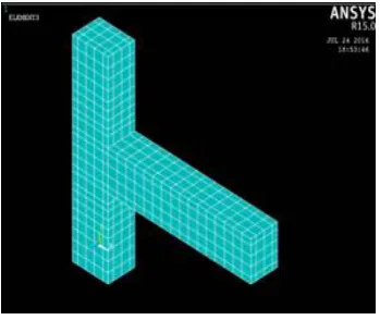
Fig. 6(a) Model meshed with SOLID 65 Fig. 6(b) Steel reinforcement detailing with elements for concrete in models LINK180 element in models
4. Analysis of Results and Discussion 4.1 Load Deflection Behavior
Load deflection behaviour for all the tested beam-column joints is shown in Fig. 7. It has been observed that the first crack load and ultimate load are obtained corresponding to 9 percent fiber contents for aspect ratio 80 and 100, when SF and ZZ fibers are used. The fiber volume contents corresponding to 9 percent has been found to be optimum, beyond which decrease in first crack and ultimate load has been observed. This may be attributed due to congestion of fiber reinforcement in the beam column junction, leaving behind honeycombing in the concrete. A nonlinear behaviour of HPFRC has been observed in all cases, primarily due to multiple cracking of HPFRC, The first crack load and ultimate loads have been found to increase by 46, 83 and 40, 48 percent in comparison to NFC in straight fibers and 110, 69 & 61, 53 percent in Zig Zag fibers at 9 percent fiber contents respectively. Similarly, First crack and ultimate deflections at location-1 in Fig.2 have been found to increase by 7, 19 & 48, 69 for straight fiber and 57, 47 & 100, 76 percent in Zig Zag fibers at 9 percent fiber contents respectively in comparison to NFC, when SF and ZZ fibers, in 9 percent fiber volume contents and 80 & 100 aspect ratio are used It is therefore established that the fiber contents corresponding to ZZ fibers 9 percent fiber volume contents is more effective in increasing the load carrying capacity of beam-column joints. The fibers are found to increase first crack load significantly, thereby enhancing elastic region and confining pressure, and also restricts initial cracking of concrete. The comparative performance of HPFRC with conventional concrete illustrates that presence of fibers in concrete effectively bridges crack width and increases bond strength between the rebar and composites and restricts the early slip of reinforcement as per detailing recommended by IS:13920. Fiber bridging effects further increasing stiffness without increasing the compressive strength in comparison to controlled concrete. The deflection values at first crack load and ultimate load have also been found to increase significantly, thereby increasing ductility associated parameters in comparison to conventional concrete.
Fig. 7. (b) Load Deflection Curve for Beam-Column Assembly Crimped Fibers (Aspect Ratio 80 and 100)
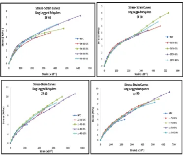
4.2 Stress Strain Characteristics
Resultant strain & stress at first crack and ultimate loads have been found to increase by 68, 96 & 17, 83 and 81, 71 & 34, 70 percent respectively in straight fibers in comparison to NFC& 114, 93 and 88, 75 percent respectively in comparison to NFC. Similarly resultant strain and stress at first crack and ultimate loads have been found to increase by 114, 93 & 109, 48 and 109, 48, & 93, 38 percent respectively in Zig Zag fibers in comparison to NFC. It has been observed that inclusion of fibers in beam-column joint region significantly increases resulting strain and stress values at first crack and ultimate load, thereby illustrating better post peak behaviour over conventional concrete. Similar kind of post yielding behaviour was observed in load deflection curves.
4.3 Failure Characteristics
The crack pattern was monitored in beam-column joint region. Fig.8 illustrate mode of propagation of cracks in this region. It has been observed the cracks were initiated from the junction, and propagated towards joint and free end of beam. Multiple cracking in the region was noticed, which conformed contribution of fibers, effectively. Flexural cracks in beam hinge region was found dominating leading to failure. Pronounced multiple diagonal cracks were found diminishing at 9 percent fiber contents using Zig Zag fiber, thereby validity effectiveness of these fibers. On higher fiber contents of 10 percent, congestion of fiber reinforcement, however, again, demonstrated poor stress and hence strain between fibers & concrete in this region
Fig. 8(b).Cracks failure in ZZ 40 / 9 and ZZ 40 / 10
4.4 Strength Characteristics
The first crack moment (Mcr), ultimate moment (Mu), resilience, toughness & ductility etc. are tabulated in
Table2. Similar behaviour of beam-column joint at 9 percent fiber contents using Zig Zag fibers were observed, thereby conforming optimum value of fiber as 9 percent.
Table 2 First Crack Moment, Ultimate Moment, Resilience, Toughness and Ductility
Designati on MCr (kN -m) Increas e in Mcr (%) MU (kN-m) Incr ease in Mu (%) Resilien ce ( kN.mm ) Increase in Resilience (%) Toughn ess ( kN.mm ) Increase in Toughn ess (%) Ductili ty Increa se in Ductili ty (%)
NFC 3.24 - 6.77 - 29 - 420 - 3.26 -
SF 40 /6 5.45 68 8.62 27 48 68 851 103 6.10 87
SF 40 /8 5.87 81 9.03 33 59 106 981 133 5.92 82
SF 40 /9 6.77 109 11.95 77 72 148 1109 164 5.72 76
SF 40 /10 6.07 87 11.64 72 69 140 1020 143 6.21 91
SF 50 / 6 6.21 91 10.95 62 59 103 944 125 6.27 93
SF 50 / 8 7.00 116 11.35 68 69 141 1026 144 6.24 92
SF 50 / 9 7.82 141 13.54 100 79 172 1182 181 5.07 56
SF 50 /10 7.20 122 12.73 88 58 102 1070 155 5.72 46
ZZ 40 / 6 9.85 204 14.48 114 62 116 1113 165 4.79 47
ZZ 40 / 8 9.21 184 15.76 133 81 182 1289 207 4.33 33
ZZ 40 / 9 9.97 208 17.23 155 109 278 1595 280 4.42 36
ZZ 40 /10 8.73 169 15.59 130 91 214 1276 204 4.89 50
ZZ 50 / 6 7.04 117 13.99 107 54 87 1063 153 5.69 75
ZZ 50 / 8 8.76 170 15.16 124 62 114 1223 191 4.34 33
ZZ 50 / 9 9.23 185 16.83 149 92 219 1495 256 4.11 26
ZZ 50 /10 8.41 160 13.23 96 79 172 1190 183 5.15 58
4.5 Envelope Curves
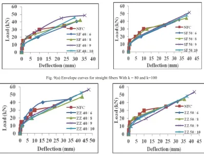
Fig. 9(a) Envelope curves for straight fibers With k = 80 and k=100
Fig. 9(b) Envelope curves for crimped fibers with k = 80 and k=100
4.6 Stiffness Degradation
During the testing of specimen under cyclic loading, materials (i.e. Concrete and Steel) are subjected to loading, unloading and reloading operations, which starts the development of micro-cracks inside the joint, leading to failure of joint at ultimate load. An increase in deformation due to development of cracks inside the beam-column joints subjected to cyclic loading, results in reduction in stiffness.
The values of secant stiffness obtained for each cycle are obtained and plotted for all the specimens as shown in Fig. 10. It has been found that, the addition of fiber to NFC does not have any effect on the first cycle and as the number of cycles increases, there is a reduction in stiffness of each specimen as compared to the NFC. This may be attributed that during the first cycle micro-cracks have not propagated and fiber have not contributed effectively due to absence of crack propagation, as the number of cycles increased further multiple cracks are developed randomly and are intercepted by fibers, which control further propagation of cracks, resulting in high energy demand.
Fig. 10(b) Relationship between stiffness and number of cycles for Crimped Fibers ( k=80 and 100)
Based on the observations made under load deflection curve, strain-stress characteristics, envelope curves and stiffness degradation, it has been observed that the application HPFRC can effectively improve performance of beam-column joints because of increased load carrying capacity, deformation capability, moment of resistance and reduced stiffness degradation prior to formation of major cracks in the joint core region.
5. Conclusions
1. The first crack load, ultimate load, first crack load deflection and ultimate load deflection are increased by 110, 61, 57 and 99 percent, respectively; in the HPFRC based beam-column assemblies, corresponding to Zig Zag steel fibers with comparison to their companion specimen.
2. Resultant strains and stresses at first crack and ultimate loads are increased by 114, 88, 109, and 93 percent respectively in HPFRC based beam-column assemblies corresponding to Zig Zag specimen, when compared with NFC beam-column assembly specimen.
3. First crack and ultimate moments have also been increased by 208 and 155 percent for beam- column assembly designated ZZ 40/9, when compared with their companion specimen NFC.
4. Ductility associated parameters; resilience, ductility and toughness are increased by 278, 36, and 280 percent in HPFRC based beam-column assemblies corresponding to Zig Zag steel fibers when compared with their companion specimen.
5. A optimum fiber content has been found corresponding to crimped fiber with aspect ratio 80 and 9 percent fiber contents.
6. The addition of steel fibers in beam-column assemblies, decreases rate of degradation of stiffness but improves dimensional stability, strength & integrity of joint as compared to NFC based specimens, hence addition of steel fibers in beam-column assemblies can be considered as a useful solution in case of assembly subjected to cyclic loading.
References
[1] Parra-Montesinos G.J., (2005), High-Performance Fiber-Reinforced Cement Composites: an Alternative for Seismic Design of Structures, ACI Structure Journal, 102(5), pp 668-75
[2] Canbolt B.A., Parra-Montesinos G.J., and Wight J.K., (2005), Experimental Study on Seismic Behaviour of High-Performance Fiber-Reinforced Cement Composites Coupling Beams, ACI Structure Journal, 102(1), pp 159-66.
[3] Elnono, M. E., Salem, H.M., Farahat, A.M., and Elzanaty, A.H., (2009), Use of Slurry Infiltrated Fiber Concrete in Reinforced Corner Connections Subjected to Opening Moments, Journal of Advanced Concrete Technology, 7(1), pp 51-59.
[4] Thirugnanam, G.S., Govindan P., and Sethurathnam, A., (2001), Ductile Behaviour of SIFCON Structural Members, Journal of Structural Engineering, 28(1), pp 27-32.
[5] Farhan J.A., Kani Z.M., (2011), Finite element modeling of high-strength fiber reinforced beam column joints, Jordan Engineers Association/Conferences.
[6] Uma S.R., and Jain S.K., (2006), Seismic design of beam column joints in RC moment resisting frames- review of codes, Structural Engineering and Mechanics, 23(5), pp 579-97
[7] Uma S.R., and Prasad A.M., (2001), Seismic behaviour of beam column joints in reinforced concrete moment resisting frames, IITK- GSDMA-EQ, 31(1).
[8] Shaikh M.G., and Sohailuddin S., (2013), Finite Element Modeling of Reinforced Concrete Beam Column Joint using Ansys, International Journal of Structural and Civil Engineering Research, Vol.2, No. 3, August 2013, PP. 22-31.
[9] Patil S.S., and Manekari S.S., (2013), Analysis of Reinforced Beam Column Joint Subjected to Monotonic Loading, International Journal of Engineering and Innovative Technology, 2(10), pp 149-58
[11]Kulkarni S.M., and Patil Y.D., (2014), Cyclic Behaviour of Exterior Reinforced Beam Column Joint with Cross Inclined Column Bars, IOSR Journal of Mechanical and Civil Engineering, 11(4), pp 9-17.
[12]Kiran R, and Genesio G, (2014), A Case Study on Pre-1970s Constructed Concrete Exterior Beam Column Joints, Case Studies in Structural Engineering, 1, pp 20-25.
[13]Roehm C, Sasmal S, Novak B, and Karusala R, (2015), Numerical Simulation for Seismic Performance Evaluation of Fiber Reinforced Concrete Beam Column Sub-Assemblages, Engineering Structures, 91, pp 182-96.
[14] Lobo P.S, and Almeida J, (2015), RC Fiber Beam Column Model With Bond-Slip in the Vicinity of Interior Joints, Engineering Structures, 96, pp 78-87.
[15]Borghini A, Gusella F, and Vignoli A, (2016), Seismic Vulnerability of Existing RC Building: A Simplified Model to Analyze the Influence of the Beam-Column Joints Collapse, Engineering Structures, 121, pp 19-29.
[16]Del Vecchio C, Di Ludovico M, Prota A, and Manfredi G, (2016), Modeling Beam-Column Joints and FRP Strengthening in the Seismic Performance Assessment of RC Existing Frames, Composite Structures, 142, pp 107-116.
[17]Zhang P, Hou S, and Ou J, (2016), A Beam-Column Joint Element for Analysis of Reinforced Concrete Frame Structures, Engineering Structures, 118, pp 125-13.
[18]Balaji S. and Thirugnanam G. S, (2016), Study on Exterior RC Beam-Column Joints Upgrade With SIFCON in Joint Core Under Reversed Cyclic Loading, KSCE Journal of Civil Engineers, 21(1), pp 346-352.
[19]Liang Xing-wen, Ying-Jun and Deng Ming-ke, (2016), Seismic performance of fiber-reinforced concrete interior beam-column joints, Engineering Structures, 126, pp 432-445.
[20] Fischer, G., (2004), Characterization of Fiber Reinforced Cement Composites by their Tensile stress-Strain Behaviour and
Quantification of Crack Formation, 6th RILEM Symposium on Fiber Reinforced Concrete (FRC)-BEFIB -2004 20-22 September.2004, Varenna. Italy, pp 331-338.
![Fig. 1 Schematic stress-strain behavior of cementitious matrices in tension [20]](https://thumb-us.123doks.com/thumbv2/123dok_us/9670669.1494988/3.595.149.442.345.479/fig-schematic-stress-strain-behavior-cementitious-matrices-tension.webp)