Drink. Water Eng. Sci., 5, 15–21, 2012 www.drink-water-eng-sci.net/5/15/2012/ doi:10.5194/dwes-5-15-2012
©Author(s) 2012. CC Attribution 3.0 License.
History
of
Geo- and Space
Sciences
Open
Access
Advances
in
Science & Research
Open Access ProceedingsDrinking Water
Engineering and ScienceOpen Access
Open
Access
Earth System
Science
Data
Drinking Water
Engineering and ScienceDiscussions
O
pen
Acc
es
s
Open
Access
Earth System
Science
Data
D
iscussions
Assessing variable speed pump efficiency in water
distribution systems
A. Marchi1, A. R. Simpson1, and N. Ertugrul2
1School of Civil, Environmental and Mining Engineering, The University of Adelaide, SA 5005, Australia 2School of Electrical and Electronic Engineering, The University of Adelaide, SA 5005, Australia
Correspondence to: A. Marchi (amarchi@civeng.adelaide.edu.au)
Received: 25 January 2012 – Published in Drink. Water Eng. Sci. Discuss.: 15 March 2012 Revised: 23 May 2012 – Accepted: 11 June 2012 – Published: 4 July 2012
Abstract. Energy savings and greenhouse gas emission reductions are increasingly becoming important de-sign targets in many industrial systems where fossil fuel based electrical energy is heavily utilised. In water distribution systems (WDSs) a significant portion of operational cost is related to pumping. Recent studies have considered variable speed pumps (VSPs) which aim to vary the operating point of the pump to match demand to pumping rate. Depending on the system characteristics, this approach can lead to considerable savings in operational costs. In particular, cost reductions can take advantage of the demand variability and can decrease energy consumption significantly. One of the issues in using variable speed pumping systems, however, is the total efficiency of the electric motor/pump arrangement under a given operating condition. This paper aims to provide a comprehensive discussion about the components of WDS that incorporate variable speed pumps (including electric motors, variable frequency drives and the pumps themselves) to provide an insight of ways of increasing the system efficiency and hence to reduce energy consumption. In addition, specific attention is given to selection of motor types, sizing, duty cycle of pump (ratio of on-time and time period), losses due to installation and motor faults. All these factors affect the efficiency of motor drive/pump system.
1 Introduction
Attention towards efficient and eco-friendly management has been growing in recent years, especially in systems char-acterized by a large consumption of non-renewable energy. Most water distribution systems (WDSs) require the opera-tion of pumps to deliver the necessary quantity of water with the adequate pressure to the final consumers. As reported by Lingireddy and Wood (1998) and Bene et al. (2010), the elec-trical energy used to pump water is a significant portion of the total operational costs in WDSs.
While sustainability has been considered in the problem only recently (Wu et al., 2010a, b), a vast literature regard-ing the minimization of energy costs in WDSs exists. In most of the cases, optimization of operations has only considered fixed speed pumps (FSPs) and the cost savings that may be obtained by exploiting a multi-pattern electric tariff (Mc-Cormick and Powell, 2003; van Zyl et al., 2004; Salomons et al., 2007; L´opez-Ib´a˜nez et al., 2008; Broad et al., 2010).
As a result the energy consumption by the fixed speed pump remains approximately the same.
P
M
ValveFlow 3 Phase
AC Mains
η
motorη
pumpη
inverterP
Flow 3 Phase
AC Mains
I
M
η
motorη
pumpa)
b)
η
VFDV
Figure 1. Simplified representation of pump systems: (a) fixed speed pumps and (b) variable speed pumps. M: motor, P: pump, V: Variable frequency drive,η: efficiency.
high efficiency by effectively scaling the pump curve as the pump speed is varied.
Although good efficiencies can be maintained by consid-ering proper options, such as using control valves or select-ing the correct number and type of parallel pumps, VSPs can still be advantageous in reducing energy consumption, water losses and pipe wear (Lingireddy and Wood, 1998). However, VSP convenience is not always guaranteed: man-uals such as Hydraulic Institute et al. (2004) or BPMA et al. (2003) describe the WDSs characteristics for which VSP are not as attractive. In addition, prediction of the total effi -ciency of VSP system is not clear specifically at light loads. Although it is known that the efficiency decreases when the speed rate is reduced (Lingireddy and Wood, 1998; Sˆarbu and Borza, 1998), Walski et al. (2003) showed that the ef-ficiency can be considerably lower than expected also for small reduction of the pump speed rate (although the pump that was tested in the laboratory was quite small).
The overall efficiency of VSP, called wire to water effi -ciency, is a result of various factors since every component in the pump system has losses. In the simplified scheme shown in Fig. 1, the main difference between VSPs and FSPs is the introduction of the variable frequency drive and the absence of the valve, which have an impact on the total efficiency of the pump system. As the wire to water efficiency depends on the particular type and size of components used and on the system requirements, the effectiveness of VSPs has to be assessed for each specific case. However, as VSPs require knowledge in different fields, this task can be complicated.
This paper aims to provide a comprehensive discussion about the components of pumping systems in WDSs (vari-able frequency drives, electric motors and pumps) to pro-vide insight into the assessment of efficiency and energy con-sumption of variable speed pumps applied water distribution systems. The next section explains why VSPs can be advan-tageous compared to FSPs. The following sections describe the interaction between pump, motor and VFD characteris-tics, and provide insights how these characteristics are mod-ified when the pump speed rate is changed. Further
discus-P
Datum
z
1p
1γ
H
Ps
f1
f2
h
H
h
System Curve
Pump Curve
Flow
H
e
a
d
Q
ReqQ
DesH
P,DesH
P,Reqoperating point
H
S a)b)
Figure 2.(a) Hydraulic grade line (dashed line) when the pump
transfers water between two reservoirs. (b) Additional energy con-sumption in case of water transmission systems (in grey). (Figure adapted from ITP and Hydraulic Institute, 2006.)
sions are also provided to assess potential motor types and motor management issues in practical systems.
2 Possibilities for energy saving in WDSs with VSPs
The energy used by a pump in a water distribution system,
E (kWh), is the product of the specific weight of water,γ
(N m−3), the flow delivered, Q (m3s−1), the increase in head across the pump, HP(m), and the operating time t (h) divided
by the wire to water system efficiency,ηww.
The pump head HP is the sum of the static head Hs, i.e.
the difference in water levels between the two reservoirs, and the friction losses before and after and the pump P, shown as hf2 and hf1 respectively in Fig. 2a. As the velocity head
can normally be neglected in WDSs, HPis representative of
the increase of energy in the flow: part of this energy will be dissipated due to the friction losses, while the remaining part will be converted from pressure to potential energy as-sociated with the increase of elevation. The friction losses hf
(the sum of hf1and hf2) are an approximately quadratic
func-tion of the fluid velocity and therefore of flow. For the same diameter pipe, if a different pump P1is used to raise a flow
therefore the new head HP1will be smaller than HP. Thus, the
energy consumed by the new pump P1 will be smaller than
the energy used by P because of the smaller flow and head. As pumps are often sized considering the system condi-tions at the end of its service life, the actual operating points can be different from the design criterion. In addition, the daily and seasonal variability in water demand can further move away the actual pump operating point from the ex-pected one.
If the pump used is a fixed speed pump, the operating point is forced to move along the pump curve corresponding to the fixed nominal speed. If the system is not modified, the sys-tem curve can possibly intersect the FSP curve in a region of low efficiency. A common way to avoid this drawback is the modification of the system curve by the insertion of valves. Although this leads to an increase in pump efficiency, it is a waste of energy because of the additional losses introduced by the valve.
VSPs can take advantage of the different required operat-ing conditions in WDSs. In particular, the reduction in en-ergy consumption exploits the possibility of reducing head or flow in the system. Figure 2b shows the case in which the required flow is smaller than the actual operating point. This can be the case of a water transmission system, where pumps are used to move water from a lower to an upper tank. Since the pumping has been at a particular time of the year may be sized for a peak-day demand, the pump will deliver a flow associated with the operating point despite the fact that the required demand is decreased (for example because of the seasonal variability). Given that smaller flows imply smaller friction losses, the grey area in Fig. 2b can be seen as energy wasted. However, this operating strategy can be eco-nomically convenient if the system has a sufficient storage volume so that pumps can be switched on only during the off-peak-tariffperiod.
The energy used by the pumping system depends also on its efficiency and the adjustment of the pump curve when VSPs are used can affect the wire to water efficiency,ηww.
The general expression of the wire to water efficiency is rep-resented by Eq. (1), whereηVFD,ηmotandηpumpare the effi
-ciencies of the variable frequency drive, of the motor and of the pump, respectively. If the pump is a fixed speed pump, there is no variable frequency drive and thusηVFD may be
taken as equal to 1.
ηww=ηVFD·ηmot·ηpump (1)
The following section of the paper will consider the impact of changing the pump speed rate on the pump efficiency,ηpump,
which will be followed by the discussions about types of mo-tors and VFDs to obtain a variable speed pump system.
Flow
H
ea
d
E
ff
ic
ie
n
cy
A
A’ B
B’
Pump Curve at N1 Pump Curve at
N2< N1
System Curve Hs> 0 System Curve Hs= 0
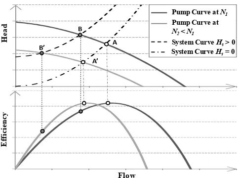
Figure 3.Operating points and efficiencies with varying speeds: in case of system with zero static head, the operating point A at the rotational speed N1moves to A0when the speed is reduced to N2,
but A and A0
maintain the same efficiency; in case of system with considerable static head the operating point at the reduced speed, B0, has an efficiency lower than the operating point B at the nominal
speed N1.
3 Pump operation at variable speeds
Pumps used in WDSs are often centrifugal pumps character-ized by the fact that the flow-head curve remains sufficiently flat for a wide range of flows. The relationships that link the pump characteristics (flow, Q, head, H, power, P) operating at different speeds (N1, N2) are described by the affinity laws:
the ratio of the pump flow rates, pump heads and pump pow-ers is a linear, quadratic and cubic function, respectively, of the pump speed ratio.
The approximation introduced in the power-speed relation implies that the efficiency will remain constant for speed N1
and N2, i.e. that the efficiency curve will be only shifted to
the left in case of speed reduction. Equation (2) is given by Sˆarbu and Borza (1998), which provides an analytical rela-tionship between two different speeds (N1 and N2) and the
corresponding efficiencies (η1,η2).
η2=1−(1−η1)·
N1
N2
!0.1
(2)
Figure 3 shows that, in a system with zero static head, the pump can operate with the same efficiency of the nominal speed. In contrast, when the static head of the system is a significant portion of the total head delivered by the pump, the efficiency of the pump operating at a reduced speed can rapidly decrease below an acceptable level.
In systems where there is a static head component, the al-lowable decrease in pump speed rate is limited by several factors. Firstly, the minimum pump speed rate is defined by the speed at which the shutoffhead of the pump corresponds to the static head of the system. Secondly, the efficiency of the new operating point should be evaluated as it is the most restrictive condition in case of system with large static head relative to the total pump head. Finally, the speed should not be reduced beyond the 70 % of the nominal speed, so to con-sider that the pump maintains the same BEP. However, as it can be observed in Fig. 1, the highest efficiency in variable speed pump systems can be achieved if all the system com-ponents (included motor and variable frequency drive) have higher efficiency at the operating points, which will be dis-cussed in the following sections.
4 Motor options
Reducing losses in motors and associated motor drives can result in substantial cost savings. In fact, pump operations account for about 20 % of the total electric energy used in industry and more than 95 % of an electric motor’s life cycle cost is related to energy consumption (Fuchsloch et al., 2008).
The majority of electric motors used in pump applications are induction (asynchronous) types as they operate directly from AC mains supply and are self starting. In addition, they are low cost machines, are reliable and have relatively high efficiency, which can be considered relatively constant if mo-tor operates above 50 % of rated load (Ulanicki et al., 2008). The rated speeds of induction motor (IM) is usually very close (typically 90–99 % depending on machine size) to syn-chronous speed that is determined by the supply frequency and can be altered by a variable frequency drive. The op-erating speed range of these motors are normally between synchronous speed (no-load) and rated speed (full-load). In IMs, the ratio of the speed difference between synchronous and rated speed relative to the synchronous speed is known as slip, s. The name plate of an IM always gives a rated speed that is slightly less than the synchronous speed, and such mo-tors are designed to deliver rated torque (that is, rated output power) at rated speed. To a first approximation the torque ver-sus speed curve of an IM can be approximated as a straight line between synchronous speed and rated speed. Although the motor characteristics can differ slightly, their efficiency varies significantly with the load and the highest possible ef-ficiency of an induction motor operating at a slip s, is equal to 1−s. For instance at a slip=0.1, the maximum possible
ef-a)
a)
b)
b)
Figure 4.The improved efficiency at rated load (a) and typical par-tial load efficiencies (b) for PM motors and energy efficient IMs (Melfi et al., 2009).
ficiency is 90 %. In practice the actual efficiency is somewhat lower than this due to other losses in the machine.
operation of a pump results in some benefits in terms of re-duced pump wear and maintenance costs (primarily due to increase in bearing life).
Although the brushless PM motors are more expensive than the induction motors, the purchase price of electric mo-tor is a small part (about 3–5 %) of the total cost of opera-tion (TCO). However, slight variaopera-tions in their operating effi -ciency could dramatically affect the TCO through electricity costs (about 70 % over their lifetime).
In addition, implementation of motor management pro-gram alone can reduce the energy usage up to 15 %, which should consider motor installation related issues includ-ing soft-foot, misalignment, poor electrical connection, poor power factor, undersized electrical conductor as well as sup-ply variation and supsup-ply unbalance. These can be considered as hidden faults in motor systems as they do not cause an im-mediate loss of operation but significantly affect the energy usage. For example, the motor set-up fault, misalignment, can increase the energy consumption up to 10 %, the extra resistances causes the bad electrical connection (called a hot joint) can reduce efficiency 1.5 %, and 2 % of supply voltage imbalance can result in a temperature increase in the motor by 10◦C that shorten the life of insulation by half as well as
cause reverse sequence of magnetic field in IMs, which cause further reduction of the efficiency.
In addition, these hidden faults also directly affect the re-liability of the system as they can develop severe faults in motors as they reduce bearing life, motor performance and efficiency as well as causing noise and vibration.
5 Variable frequency drives
Variable frequency drives (or variable speed controllers) can simply control motor speed by varying effective voltage and frequency, which is obtained from a fixed voltage and fixed frequency three-phase mains supply. Brushless PM motors cannot operate without a variable frequency drive due to their structure. However, from a cost and complexity point of view, there is not much difference between the variable frequency drives used in IMs or brushless PM motors for the same power ratings. Although there are different types of VFDs and control schemes, they should be assessed together with the choice of a motor.
There have been difficulties in estimating and measur-ing the efficiency of a motor (IM or brushless PM motor) controlled by a variable speed controller. Internationally ap-proved standards or testing procedures of motor/VFD com-bination are not available at present (Stockman et al., 2010). Since the variable frequency drive can operate the motor over a wide range of speeds, it is important to know efficiency values of VFD/motor combination at each operating point to accurately determine the operating point of a pump, which is known as iso-efficiency contours. Stockman et al. (2010) have reported a successful measurement procedures how to
River
Pumping station
Town
Tank
HGL
Figure 5.Case study layout and its EPANET representation. The hydraulic grade line (HGL) of the pump run at reduced speed (dashed line) has a flatter slope than the HGL at full speed (con-tinuous line).
obtain the iso-efficiency contours of VFDs connected to both IMs and brushless PM motors. It was demonstrated that the brushless PM motor has far better efficiency values compared to IM.
It should be noted here that in variable drive systems, there are additional losses generated in the motor by the variable frequency drive. In addition, the VFDs perform rapid switch-ing of DC voltages across the motor windswitch-ings which can cause damage to the motor insulation (resulting reduced mo-tor life) which is normally only designed for sinusoidal volt-ages. Therefore, in variable speed pump applications it is im-portant to use motors that have specially designed insulation to allow them to handle with VFD operation.
6 Case study
A case study is presented to show how the efficiencies of variable frequency drive, motor and pump impact the VPS power. The case study consists of a pump that lifts water from a reservoir to a tank while supplying customers (Fig. 5). If the pump can be run at a reduced speed, the hydraulic grade line will have a flatter slope than the one at full speed, because of the reduced flow and hence reduced head losses.
It is assumed that during the low demand periods (e.g. at night) the pump speed can be reduced to 75 % of the full speed, while still meeting the water supply requirement, i.e. the same amount of water is pumped during the day, often resulting in the VSP being run continuously.
The hydraulic model of the case study (lower part of Fig. 5) has been implemented in EPANET 2 (Rossman, 2000). EPANET uses the affinity laws to compute the pump characteristics at the pump reduced speed: the simulation results show that pump flow and head are 51.9 l s−1 and
the pump is 37.40 kW. However, the motor and variable fre-quency drive efficiencies also need to be considered to com-pute an accurate estimate of the total power.
The efficiency of the motor is related to motor type, size and load as shown in Fig. 4. At full speed the pump power is 86.84 kW (flow=65.3 l s−1, head=110.59 m and pump effi
-ciency=81.48 %). However, considering that the maximum power of the pump is 104 kW, a motor size of 110 kW was chosen. Therefore, during normal operation at full speed, the motor works at 79 % (86.84/110×100) of the full load; at the reduced speed the motor load is reduced to 34 %. Assuming that the motor characteristics are those presented in Fig. 4b for an energy efficient motor, the motor efficiency is about 94.7 and 93 % for the pump run at full speed and at the re-duced speed of 75 %, respectively.
The variable frequency drive efficiency depends on the VFD type, size and on the speed reduction. If the data re-ported in the Industrial Technologies Program (2008) are used, the VFD efficiency for our case study is 97 %. How-ever, to be on the safe side, data from Bernier and Bour-ret (1999) are used, and the VFD efficiency is assumed to be equal to 92 %. Therefore, when the pump is run at 75 % of the full speed, the power required is 43.7 kW as shown by Eq. (3) when Q=51.86 l s−1, H=61.03 m,η
VFD=0.92,
ηmot=0.93 andηpump=0.83. This value is about half of the
power required at full speed, i.e. 95.2 kW (Q=65.27 l s−1,
H=110.59 m,ηVFD=0.97,ηmot=0.947 andηpump=0.81).
P (kW)=
9810mN3
·Q (m3s−1)·H (m)
ηVFD·ηmot·ηpump
· 1
1000 (3)
Note that the power required for the VSP to run at full speed is larger than the power required for a FSP (95.2 vs. 92.1 kW) because of the VFD efficiency (0.97 in this case) that de-creases the wire-to-water efficiency also when the pump is run at full speed. Therefore to assess the effectiveness of VSPs the duty cycle of the pump has to be known. Assum-ing that in normal operations the FSP is switched on for 19 h per day, the pump operation consumes 1754 kWh day−1 to
pump 4465 m3day−1(corresponding to 0.393 kWh m−3). We also assume that the VSP can be run at the relative speed of 75 % for 24 h. If VSPs are used, the energy consumption is 24×43.7=1049 kWh day−1 (4481 m3day−1 pumped corre-sponding to 0.234 kWh m−3). Assuming that a cooling sys-tem is not required for the pump in the case study, VSPs save energy. Note that computations are here simplified for ease of discussion, but in reality the VSP speed is likely to vary during the day to comply with the network requirements. For example, depending on the size of the tank and on the de-mand profile, the pump could be forced to work at full speed during the high demand periods, increasing its energy con-sumption.
Finally, to assess the effectiveness of VSPs, capital costs of the investment have to also be evaluated and compared to the energy saving during the lifetime of the project. VSPs
are usually more effective in existing systems where the ac-tual pumps may be operating in response to conditions dif-ferent from the ones they were designed for. However, it is worth noting that VSPs are only one option among others and therefore also the life cycle analysis of the other options has to be considered so as to indentify the best solution.
7 Conclusions
This paper considers the energy saving that may be obtained by the introduction of variable speed pumps in water distri-bution systems. This assessment should evaluate pump and pipeline characteristics, load cycle and efficiency character-istics of the motor.
Variable speed pumps can provide significant economies if the WDS is characterized by a high variability of operat-ing conditions, so that the advantages of adjustoperat-ing the pump operating point can be fully exploited. In this perspective, systems characterized by a large static head are penalised be-cause of the limited speed range the pump can operate and because of the substantial decrease in pump efficiency. In ad-dition, the introduction of the variable frequency drive low-ers the wire to water efficiency of the system. Moreover the efficiency of the motor and the pump are also lower when op-erated at lighter loads and lower speeds. Although induction motors are commonly used in WDSs with FSPs, brushless PM motors offer significantly higher efficiency and higher power factor specifically at low speeds and light loads. In ad-dition, motor installation related issues play a significant role in the total efficiency of the system.
Acknowledgements. We would like to thank the Editor Guang-tao Fu, Tom Walski and the other anonymous reviewer for their comments, which improved the quality of this paper.
Edited by: G. Fu
References
Bene, J. G., Selek, I., and H¨os, C.: Neutral search technique for short-term pump schedule optimization, J. Water Res. Pl.-ASCE, 136, 133–137, 2010.
Bernier, M. A. and Bourret, B.: Pumping energy and variable fre-quency drives, ASHRAE J., 41, 37-40, 1999.
British Pump Manufacturers’ Association (BPMA), Gambica’s Variable Speed Drive group and Electric Motor industry: Vari-able speed driven pumps – Best practice guide, 2003.
Broad, D. R., Maier, H. R., and Dandy, G. C.: Optimal operation of complex water distribution systems using metamodels, J. Water Res. Pl.-ASCE, 136, 433–443, 2010.
Fuchsloch, J. F., Finley, W. R., and Walter, R. W.: The Next Gener-ation Motor, IEEE Ind. Appl. Mag., 14, 37–43, 2008.
Industrial Technologies Program: Adjustable speed drive part – load efficiency, Motor Tip #11, US Department of Energy, Energy Ef-ficiency and Renewable Energy, June 2008.
Lingireddy, S. and Wood, D. J.: Improved operation of water dis-tribution systems using variable-speed pumps, J. Energ. Eng.-ASCE, 124, 90–102, 1998.
L´opez-Ib´a˜nez, M., Prasad, T. D., and Paechter, B.: Ant Colony Op-timization for Optimal Control of Pumps in Water Distribution Networks, J. Water Res. Pl.-ASCE, 134, 337–346, 2008. McCormick, G. and Powell, R. S.: Optimal pump scheduling in
wa-ter supply systems with maximum demand charges, J. Wawa-ter Res. Pl.-ASCE, 129, 372–379, 2003.
Melfi, M., Evon, S., and McElveen, R.: Induction versus Permanent Magnet Motors, IEEE Ind. Appl. Mag., 15, 28–35, 2009. Rossman, L. A.: EPANET2. EPA/600/R-00/057, Water Supply
and Water Resources Division, National Risk Management Re-search Laboratory, Office of research and Development, USEPA, Cincinnati, Ohio, USA, 2000.
Salomons, E., Goryashko, A., Shamir, U., Rao, Z., and Alvisi, S.: Optimizing the operation of the Haifa-A water distribution net-work, J. Hydroinform., 9, 51–64, 2007.
Sˆarbu, I. and Borza, I.: Energetic optimization of water pumping in distribution systems, Period. Polytech. Mech., 42, 141–152, 1998.
Stockman, K., Dereyne, S., Vanhooydonck, D., Symens, W., Lem-mens, J., and Deprez, W.: Iso Efficiency Contour Measurement results for Variable Speed Drives, in: Proceedings of the XIX International Conference on Electrical Machines, ICEM, Rome, Italy, 6–8 September, 2010.
The US Department of Energy’s Industrial Technologies Program (ITP) and the Hydraulic Institute (HI): Improving pumping sys-tem performance: A sourcebook for industry, The United States Department of Energy Office of Energy Efficiency and Renew-able Energy, 2006.
Ulanicki, B., Kahler, J., and Coulbeck, B.: Modelling the efficiency and power characteristics of a pump group, J. Water Res. Pl.-ASCE, 134, 88–93, 2008.
van Zyl, J. E., Savic, D. A., and Walters, G. A.: Operational op-timization of water distribution systems using a hybrid genetic algorithm, J. Water Res. Pl.-ASCE, 130, 160–170, 2004. Walski, T., Zimmerman, K., Dudinyak, M., and Dileepkumar, P.:
Some surprises in estimating the efficiency of variable speed pumps with the pump affinity laws, in: Proceedings of the World Water and Environmental Resources Congress 2003, Philadel-phia, PA: ASCE, 1–10, 2003.
Wu, W., Maier, H. R., and Simpson, A. R.: Single-objective ver-sus multiobjective optimization of water distribution systems ac-counting for greenhouse gas emissions by carbon price, J. Water Res. Pl.-ASCE, 136, 555–565, 2010a.