IJSRSET173214 | 01 March 2017 | Accepted: 08 March 2017 | March-April-2017 [(2)2: 16-26 ]
© 2017 IJSRSET | Volume 3 | Issue 2 | Print ISSN: 2395-1990 | Online ISSN : 2394-4099 Themed Section: Engineering and Technology
16
Effective use of Casting simulation for improving Bearing
Housing Casting’s Yield
Shubham Sanjay Sorate
1, Priya Umesh Kanase
2,
Prof. Bhushan Shankar Kamble
3Prof. Mahesh Sadashiv Sawant
41,2 UG student, Department of Mechanical engineering, TKIT, WaranaNagar, Kolhapur, Maharashtra, India 3Assistant Professor, Department of Production Engineering, KIT‟s College of Engineering, Kolhapur, Maharashtra, India
4Assistant Professor, Department of Mechanical Engineering, TKIT,Warananagar, Kolhapur, Maharashtra, India
ABSTRACT
Casting defects can negatively impact the bottom line of foundry. A defect in a casting deteriorates casting surface quality and mechanical properties. It is responsible for loss of profitability, quality level and productivity of component. Hence it is preferably necessary to reduce it as much as possible by appropriate analysis. As far as the casting with thick sections are concerned, finding the Hot Spot is very important, asMost of the casting defects occur due to “Hot spot” which is the part of casting that gets solidified last. This paper presents case study carried out in local foundry over Bearing Housing to minimize casting rejection due to major defects like blow hole and shrinkage cavities. Study is focused on route cause analysis of Blow holes and shrinkage cavities defect which contribute heavypercentage of rejection.The objective of this research is to optimize gating system by using simulation software with proper location of Feedaids like Riser, vent holes , chills and insulating sleeves based on pictorial results based on CAD and simulation tools with the goal of improving casting quality and increasing casting yield
Keywords: Casting Defects, Blow Holes, Hot Spot, Feedaids, Simulation Software, Casting Yield.
I.
INTRODUCTION
Casting is a traditional manufacturing process in which a liquid metal is usually poured into a pre-shaped mould, which contains a hollow cavity /impression of Pattern followed by solidification and post treatments as shakeout and fettling etc. The main objective of a gating system is to feed clean molten metal poured from ladle to the casting cavity, ensuring smooth, uniform nonturbulent flow and complete filling which results into the sound defect free casting.As it is a secondary component of casting, it should be kept with minimum volume so as to must consume less metal, to reduce melting and energy cost ultimately improve casting yield.In Shrinkage defects, a discontinuity that forms as aresult of the volume contraction during solidification inregions where local metal filling is insufficient or
even absent.This occurs in regions which are locally the last to solidify(hot spots). Blowhole is relatively large shrinkage cavity, formed at hot spots.
II.
CASE STUDY AND PROBLEM DEFINITION
binder and moisture content generally less than 3%.After packing, carbon dioxide gas at about 1.3-1.5 kg/cm2 pressure is then purgdall round the mold surface to about 20 to 30 seconds using CO2 head or probe or curtain. The special pattern can also be used to force the carbon dioxide gas all around the mold surfaces. The sodium silicate presented in themold reacts with CO2 and produce a very hard constituents or substance commonly called assilica gel.This hard substance is like cement and helps in binding the sand grains.
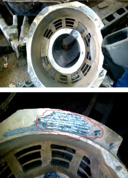
The casting weights up to 415 Kg. Currently Foundry producing castings are facing rejection problem for bearing housing. The major rejection is due to the shrinkage and blow hole defect as shown in Fig.1 which contributes up to 7 % to 13 % of total rejection. For sustainable quality of component foundry requires to reduce the percentage of rejection to optimum level.
Figure 1. Blow Hole Defect in Bearing Housing
III.
OBJECTIVE
To overcome mold cavity filling related defects because of air entrapment and inadequate sized and located riser/feeder,a well-designedrunner and gating system is
very important in producinggood quality castings by providing a uniform andhomogenous mould filling .Virtual casting simulation hasbecome a powerful tool to predict the location of defects andeliminate them by visualizing mould filling, solidification andcooling. Click 2Cast casting simulation software isused to predict defect location and in optimizing ingateand feeder size and its location which willminimize defects like hot spot, shrinkage cavities, blowholes, gas porosity etc. The simulation done over Click 2cast software provides realresults virtually which resembles with actual shop floor results [9].
IV.
LITERATURE REVIEW
Manjunath et.al [2] has optimized the gating and risering system by using ADSTEFAN casting simulation software with various iterations; it is found that a sound casting could be obtained by modifying the initial gating ratio, by altering the location of sprue from centre to end and by allocating the risers at location prone to formation of shrinkage porosity.
M. Masoumiet.al [3] has experimented a direct observation method showing various flow patterns resulting from different gating .The experimental results indicates the geometry and size of the gate and shows that the ratio of the gating system could have a great influence on the pattern of mold filling.
P. Prabhakara Rao et.al [5] has discussed with a PROCAST simulation tool and its application to a crusher component that was prototyped via sand casting process. Results of casting trials had showed a high level of confidence in the simulation tool known as PROCAST. Which is a three dimensional solidification and fluid flow package developed to perform numerical simulation of molten metal flow and solidification phenomena in various casting processes, primarily die casting (gravity, low pressure and high pressure die casting) and sand castings.
Vipulet.al [6] has investigated and described about the porosity formation in the Housing. The capability to produce sound casting component of high quality and at the same time, reducing product costs & development times is the most challenging job for the foundry today.
AUTOCAST. It is studied and experimented that casting simulation use can minimize the wastage of resources required for trial production. In addition, the optimization of quality and increased yield implies higher value-addition and lower production cost and improving the profit.
B. S.Kamble et.al [9] has studied and discussed about optimization of gating system for a casting using simulation software which reduces various casting defects and also reduces manufacturing lead time. The virtual simulation helps in optimizing a casting design by detecting the part features with potential flow and solidification problems, evaluating gate system and overflow design alternatives.
U. S. Khade et.al [10] has redesigned gating system and its components For increasing the yield of casting using AUTOCAST simulation software. It is found that after modification in the gating system and risers the yield improved is 7 % with thesound brake disc casting.
Sachin L. Nimbulkar et.al [11] has observed that, the solidification simulation enables visualization of the progress of freezing inside a casting and identification of the last freezing regions or hot spots. The different review shows that simulation can be of great use in optimizing the feeder dimensions and increasing the feeding efficiency of the casting.
Bhatt H. et.al [12] has suggested that the design optimization of feeding system and simulation of cast iron in foundries can reduced the casting defects which were arise during solidification and filling process.
B. S. Kamble [13] has reviewed several casting defects and their causes of occurrence. This will help in analysing the defect and remedies to overcome them.
V.
METHADOLOGY
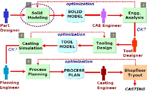
Generation of three dimensional model of the mold incorporating feeder cavities and gating entitles has recently been adopted attempted for visualization and the process simulation, this requires the additional input from the user regarding the location of the mold box sprue, runners and ingates.Graphic simulation of mold filling is of great help to designers in evaluating gating design. Availability of powerful computers has catalyzed.
Figure 2. Casting Simulation Methodology
Two different simulation iterations i.e with and without feeders are done using virtual simulation software. The results are observed for hot spot, micro porosity location and there severances in casting. By doing so an optimum sized feeder with or without insulating sleeve is designed and located at proper location so as to shift hotspot in riser/feeder. The second iteration is carried and observed for occurrence of defect.
VI.
CASTING SIMULATION
A. First simulation iteration without Feeder / Riser.
1. Generation of CAD Model
We had created the 3D model of the part using CATIA V5-R16 version and converted it to .stl file format which is compatible to open in Click 2Cast simulation software. All engraved fonts and sharp corners from part or geometry are erased for ease in meshing.
2. Generation of meshing and part material selection
Figure 4. Advanced meshed model in Click2Cast
Advanced meshing method is adopted. Meshing element size 15 mm with 215300 tetrahedral, 66852 Triangular, 53366 nodes, 3.2131e+007 mm3 and modulus 15.9826 mm meshing is generated. Silica sand moldmaterial is selected with mold temperature of 300c .Basic Process parameters like ingate velocity of 20 m/s and mold filling time of 60 sec is selected.
3. Material Specification
The Bearing housing, a component under study is a critical SG cast iron material casting which has metallurgical composition as C (0.22±0.02%), Mn (0.6±0.05%), Si (0.5±0.05%), S (0.03%max), P (0.03%max) with remaining Fe as balance. Under Cast iron group SG1 type material with temp of 17500c is selected for further simulation for both the simulation iterations.
4. Ingate size and location
Figure 5. Gating system and advanced pouring location
The ingate is the most restrictive orifice in the total fluid flow concept of the moldfilling operation in sand casting operation. As per the gating ratio which may be a pressurised or unpressurised gating system, ingate cross sectional area may be increased or reduced as compared to cross sectional area of runner and sprue. It is the point at which the metal enters into the moldcavity. Most of the casting defects such as bad surface,mold wash, improper filling, flow marks, cold shuts,and turbulent flow [13]are caused due to improper gating size and location. In this case advanced ingatepouring basin is selected as shown in Fig.5 for further simulation for both the simulation iterations.
5. Running the simulation:
Click2Cast is an advanced and innovativecasting process simulation tool that basically simulates mold filling and solidification virtually and predicts defect location. This will help you save energy, material and eventually use less of the resources. Simulations visualize the consequences of a specific design of gating system. Casting defects, such as porosity, cold-shuts, shrinkage cavities can beavoided by optimizing the design and location of the gating system [9].
6. Flow Simulation
Casting Simulation is carried over SG cast iron material .The various processparameters conditions were considered while doing thefilling analysis as metal temperature of 17500c and mold temperature of 300C with a fill time of 60 seconds and ingate velocity of 20 m/s.
7.Simulation Results and Discussion:
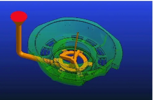
7.1 Front Flow Results:
Front flow results show the filling molten metal evolution in sand mold cavity as shown in Fig.6. This virtual visualization gives a preliminary idea of the filling time, and the way in which casting cavity is filled. It is useful to decide the position of ingate and overflows to avoid air entrapment. Because of improper location of ingate there are chances of turbulent flow in metal which may arises defects like pin holes ,moldwash, mold erosion and lap etc.
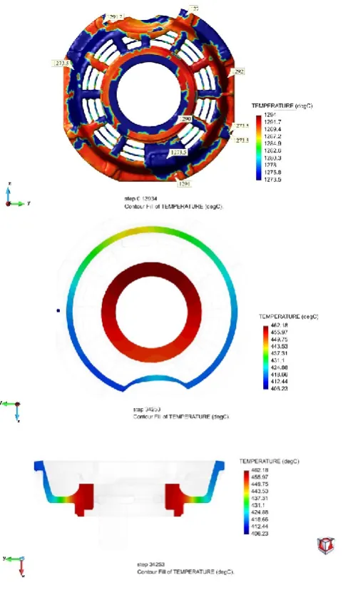
7.2 Temperature Evolution Results
The metal being poured from a ladle into a CO2moldedmold must have high temperatures in order to produce good quality castings. The temperature of the molten metal should be ideal and not too high as it influences the casting density.
Figure 7. Temperature evolution simulation results without riser
The lack of temperature may cause cold shut and misrun defects[13]. As shown in Fig.7 Temperature evolution during fillingmold cavity. With this simulation it is possible to predict temperatures at which two advancing fronts/ streams of molten material overlaps and possible chances of risk of cold welding at overlapped junction.
7.3 Metal Velocity Results
The molten metal flow inside the casting mold cavity with very high velocity leads to flash/fin and turbulent flow. It is a thin web or fin of metal on a casting which occurs at partings plane in the form of projection. The red colour velocities are highest at ingate entry. The velocity simulation is very much useful in designing the overflows which need to present in component.
Figure 8. Metal entering velocity simulation results without riser
As the filling velocity increases, the density of the casting increases up to a certain limit and decreases rapidly. High quality castings must have high density and thus higher velocity affects the quality of the castings [14].
7.4 The Pressure Distribution Results:
The objective of performing a pressure simulation on the casting is that the component should have uniformpressure distribution when the molten metal is fully filled inside the cavity. This is also used to predict the possibilities of formation of turbulent flow which might occur during the flow of metal inside the cavity. As shown in Fig.9 an negative pressure during the flow may indicate possibilities of turbulent flow. Metal turbulence may leads to defects in the component like gas porosities, shrinkage porosity etc.[13,14]. The simulation shows uniform metal entry atevery corner of mold cavity. This in turn will produce betterquality castings.
7.5 Cold Shut Results:
Figure 10. Cols Shut simulation results without riser
These are formed when a small portion of molten metal comes into contact with sand mold and rapidly cools. Metal splatters during pouring and solid globules are formed andbecome entrapped in casting. As the occurrence of the defect depends upon thethermal energy of the liquid, effective superheat (superheat at whichthe liquid meets the solid metal) is the most important variable affecting the cold shot formation. The collision of two liquid metal streams also causes' the formation of cold shuts due to splashes which 'quickly solidifies on themold wall. In any case the presence of a cold shot means the existence of an at least partial microstructural discontinuity with respect to other regions of the cast. Thus, cold shots can also be internal defects. Cold shuts option shows the front encounter of material during the evolution of the filling. The blue areas are where fronts encounter material in
cast component. This option is useful in prediction of the cold union‟s formation.
7.6 Air Entrapment and gas porosity Results:
Gas porosity is the formation of bubbles within the casting after it has cooled. This occurs because most liquid materials can hold a large amount of dissolved gas, but the solid form of the same material cannot, so the gas forms bubbles within the material as it cools. Internal gas-related defects are spherical or round-shaped cavities (often known as macro porosity for their small size) characterized by their smooth surface. The air entrapment option shows the last areas tofill the part and the air entrapment during the evolution offilling. As shown in Fig.11, The blue areas are regions where there is air entrapment. Thisoption is useful in order to avoid porosity or change theoverflows position in case of die casting process by providing vent holes and/or by providing overflows. As shown in Fig.12, The coloured dots in casting shows possible locations of macro porosity and its mass distribution
Figure 11. Air entrapment simulation results without riser
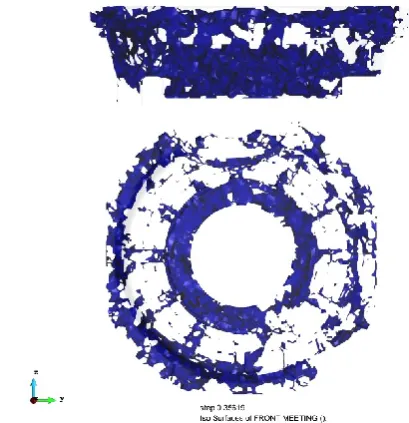
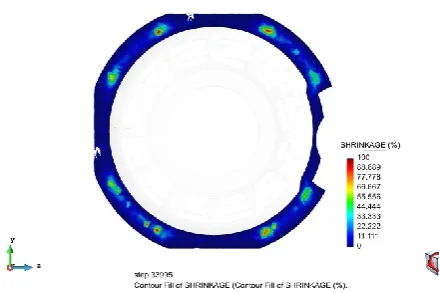
7.7 Shrinkage cavities Results:
Shrinkage defects can occur when standard feed molten metal is not available to compensate for shrinkage as the thick metal solidifies. It generally occurs at portion of casting with thick cross section.Shrinkage-related casting voids are caused by heavy sections of the casting that solidify later than the surrounding sections and do not have enough metal flow into the thick section for a complete metal filling. This is generally because the area is too hot for too long due to a thick section or a tight corner. Shrinkage porosity will have a dendritic (jagged) or linear appearance and can occur in either the cope or drag portion of the casting, usually below the surface.
Figure 13. Shrinkage areas in simulation results
Figure 14. Sectional view A showing Shrinkage areas responsible to form Hotspot
Figure 15. Sectional view B showing Shrinkage areas
responsible to form Hotspot
As shown in fig.14 and 15, The results of simulation revels red coloured regions where there are more chances of generating shrinkage defects. This can be
overcome by using feedaids as chills, feeder with or without insulating sleeve with appropriate changes in feeding parameters, such as feeder location, feeder shape and size, feeder neck shape and size.
7.8 Mold filling time results:
Mold filling process is one of the key to get a sound casting quality, which involves a liquid metal flow and temperaturefields coupled. And its various parameters such as filling velocity and temperature directly affect thecasting form. Mold filling time depends on dimensions of gating system as runner, ingate and downsprue. For better quality the cavity should be filled in minimum time with less turbulence.by observing the colour pattern, the portion of casting to be filled lastly can be predicted.
Figure 16(a). Mold filling time in simulation results
7.9 Temperature evolution graph:
Figure 16(b). Graphical representation of temperature
When the filling process is finished, the molten metal becomes solidified simultaneously. The Solidification process is influenced by a number of factors, such as filling process analysed above and temperature variation.As shown in Fig. 17 This option generates graphs. By clicking on differentpoints of the geometry nodes a graphical representation willbe generated automatically to visualize evolution of temperature of these points in relation to time.In solidification process, the distribution of shrinkage porosity and shrinkage cavity caused byfilling and solidification process has been predicted.
7.10 Casting Solidification time results:
The solidification time of a casting is a function of the volume of a casting and its surface area (Chvorinov‟s rule). Solidification time “T” of a casting is given by the formula
T=C (Volume/surface area)n
WhereC is the constant that reflects the mold material, the metal properties (including latent heat), and the temperature. The parameter „n‟ usually takes the value 2. More the casting thickness and solidification time more are the chances to generate hotspot defect at particular location.
Figure 17. Sectional viewA of casting showing last
region to freeze without riser
Figure 18. Solidification modulus results
Figure 19. Sectional viewB of casting showing last
region to freeze
B. Second casting simulation iteration with Feeder/Riser.
1. Generation of CAD model with riser:
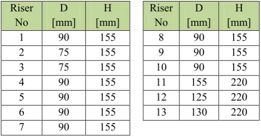
We had created the 3D model of the part with riserusing CATIA V5-R16 version along with feeders at exact locations which are prone to be defective by hotspot and converted it to .stl file .The gating system is kept same as in first iteration.Following are the riser details.
Table I : Riser Height and Diameter
Riser No
D [mm]
H [mm]
Riser No
D [mm]
H [mm]
1 90 155 8 90 155
2 75 155 9 90 155
3 75 155 10 90 155
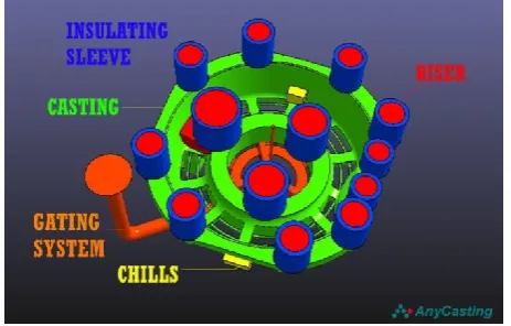
Figure 20. Solid model of casting along with riser, and feedaids as insulating sleeve and chills at proper
location
2. Generation of meshing and part material selection:
Figure 21. Advanced meshed solid model with riser
with meshing size of 15mm.
Advanced meshing method is adopted. Meshing element size 15 mm meshing is generated. Silica sand mold material is selected with mold temperature of 300c .Basic Process parameters like ingate velocity of 20 m/s and mold filling time of 60 sec is selected which are same as in iteration 1.
3. Simulation Results Design and Discussion (With Riser) :
Figure 22. Sectional view A of casting showing last
region to freeze with riser
Figure 23. Sectional viewB of casting showing last
region to freeze with riser
Figure 24. Shrinkage areas in simulation results with
feeder
By observing the colour coding and observation of simulation results of shrinkage, macroporosity and solidification as shown in Fig.22-25 it is seen that the metal remains in liquid state as solidification promotes the riser is the last portion of gating system to get solidified. Hence formation of Hotspot is shifted to riser hence reducing shrinkage formation inside the casting. Hence purpose of providing feedaid is satisfied for improving casting yield and quality.
VII.
IMPLEMENTATION OF REJECTION
CONTROL STRATEGY BY CARRYING OUT
SHOP FLOOR TRIAL
Figure 26. Process flow in metal casting process
Based on strategy formed, action plans are formed. Literature survey and hand-books are very useful while preparing the action plan to be implemented. These may be related to the effective use of the existing equipment, requirement of additional equipment, training to the employees, changes in layout etc. Action plans were implemented in phases and results are recorded. Based on the initial results, action plan will be modified if required and the same cycle will be repeated to control the rejection.
VIII.
COLLETCION OF DATA
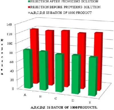
Once the reasons for the data collection have been established and decisions are made on the type of data to be collected. After gathering the required data it was analyzed to assess the findings by using Bar and Pie charts.
Figure 27. Chart showing SQC analysis of data
collected using Bar charts considering data of rejection before and after implementation of stratagies.
TABLE III: comparative ststement showing effect of
use of simulation and feedaids on casting rejection
Major Defects Before After
Blow holes 12.3 % 8.5%
IX.
CONCLUSION
With effective utilisation of resources and virtual simulation tools, SQC tools the casting rejection is reduced from 12.3 % to 8.5%. Hence Casting simulation is very powerful tool which is used to predict the growth of the process before physically performing the process. Use of simulation software reduces overall cost of developing the method for new casting by minimizing the time as well as labour cost involved in it. Process trials can be performed quickly on simulation software and optimum results can be obtained which ultimately increase the profit margin of the foundry. The SQC tools provide effective information about quality and from SQC tools we get quick information related defects. Though substantial reduction in rejection levels can be achieved due to analysis of the rejections, suggestions made for process improvements and use of better equipments, instruments as well as infrastructural changes.
X.
REFERENCES
[1] LM-6 Aluminium Alloy Casting”, IOSR Journal of Mechanical and Civil Engineering (IOSR-JMCE) ISSN: 2278-1684 Volume 4, Issue 2 (Nov. - Dec. 2012), PP 32-38, www.iosrjournals.org.
[2] Manjunath Swamy H.M, J.R.Nataraj, C.S.Prasad, “Design Optimization of Gating System by Fluid Flow and Solidification Simulation for Front Axle Housing”, International Journal of Engineering Research and Development,vol.4,PP.83-88,October 2012.
[3] M. Masoumi, H. Hu, “Effect of Gating Design on Mold Filling”, Transactions of the American Foundry Society, Vol-113,Pg 185-196, 2005. [4] Naveenkumar, Bharat.S.Kodli, “Design
Technology, Volume 2, Issue 4, Aug-Sept, 2014, ISSN: 2320 – 8791,
[5] P.Prabhakara Rao, G.Chakraverthi, A.C.S.Kumar, B.Balakrishna, “Application of Casting Simulation for Sand Casting of a Crusher Plate”, International Journal of Thermal Technologies, Vol.1.No.1 (Dec2011)
[6] Vipul.M.Vasava, Prof.D.R.Joshi, “Identification of Casting Defects by Computer Simulation-A Review”, IJERTTV Vol.21.Issue.August-2013. [7] Naveen Hebsur and Sunil Magshetty,Jully2014,
“Casting Simulation For Sand Caseting of Flywheel”IOSR Journal of Mechanical and Civil Engineers (IOSR-JMCE),Volume-11, Issue-04, PP.37-41.
[8] Pradnyesh V. Kadam, Bhushan S. Kamble, Optimization of Feeder Design Using virtual Simulation Technique - A Case Study, International Research Journal of Engineering and Technology, Volume 03 Issue: 05 , PP: 1334-1339. [May-2016]
[9] Bhushan S. Kamble ,Sandeep M. Kadane, Design of Gating System, Metal Flow and Solidification for a Die Casting Component Using Virtual Simulation Technique, International Research Journal of Engineering and Technology [IRJET], Volume 3 Issue 6, PP: 1690-1695,[June-2016] [10] Utkarsh S. Khade and Suresh M. Sawant, Gating
Design Modification Using 3D CAD Modeling and Casting Simulation for Improving the Casting Yield, International Journal of Advanced Mechanical Engineering.ISSN 2250-3234 Volume 4, Number 7 (2014), pp. 813-820.
[11] Sachin L. Nimbulkar, Dr. Rajendra S. Dalu, Design and Optimization of Gating and Feeding System for Casting: A Review, International Engineering Research Journal (IERJ) Special Issue 3 Page 93-96, 2016.
[12] Bhatt H. and Barot R, A design optimization of feeding system and solidification simulation for cast iron, proceeding on 2nd International Conference on Innovations in Automation and Mechatronics Engineering, 14(2014) 357-3 [13] Bhushan S. Kamble, Analysis of Different Sand
Casting Defects in a Medium Scale Foundry Industry - A Review, International Journal of Innovative Research in Science, Engineering and Technology , Vol. 5, Issue 2, PP:1281-1288 ,[Feb 2016],