R E S E A R C H
Open Access
Analysis of biomechanical behavior of 3D
printed mandibular graft with porous
scaffold structure designed by topological
optimization
Jiajie Hu
1, Joanne H. Wang
2, Russel Wang
3*, Xiong Bill Yu
4, Yunfeng Liu
5and Dale A. Baur
6Abstract
Background:Our long-term goal is to design and manufacture a customized graft with porous scaffold structure for repairing large mandibular defects using topological optimization and 3D printing technology. The purpose of this study is to characterize the mechanical behavior of 3D printed anisotropic scaffolds as bone analogs by fused deposition modeling (FDM).
Methods:Cone beam computed tomography (CBCT) images were used to reconstruct a 3D mandible and finite element models. A virtual sectioned-block of the mandible was used as the control group and the trabecular portion of the block was modified by topological optimization methods as experimental groups. FDM (FDM) printed samples at 0, 45 and 90 degrees with Poly-lactic acid (PLA) material under a three-point bending test. Finite element analysis was also used to validate the data obtained from the physical model tests.
Results:The ultimate load, yield load, failure deflection, yield deflection, stress, strain distribution, and porosity of scaffold structures were compared. The results show that the topological optimized graft had the best mechanical properties.
Conclusions:The results from mechanical tests on physical models and numerical simulations from this study show a great potential for topological optimization and 3D printing technology to be served in design and rapidly manufacturing of artificial porous grafts.
Keywords:3D printing, Anisotropic behavior, Finite element analysis, Fused deposition modeling, Mandibular graft, Poly-lactic acid, Topological optimization
Introduction
Autograft and allograft are commonly used for bone grafting procedures to repair segmental bony defects, which usually result from trauma, infection and tumor resection of tumors [1–3]. The limitations of autografts are donor site morbidity [4], lack of bone volume for a large defect [5, 6], and possible nerve damage. While allografts are limited by anatomical variations, genetic differences, and possible disease transmission [7,8]. It is important to restore a critical-sized mandibular defect to
its original size and shape to achieve desirable facial es-thetics and functional outcome for subsequent pros-thetic reconstruction. Microvascular free fibular graft is a common method for mandibular reconstructions to repair a large segmental defect [9–12]. It is impossible of using a fibular bone to match the shape and size of the resected portion of a mandible. Therefore, there are many prosthetic complications for those patients who received surgical and prosthetic reconstruction of the mandible [13]. One promising approach for obviating the aforementioned complication is the implementation of 3D printing strategies for the manufacturing of cus-tomized artificial bio-graft [14,15].
* Correspondence:[email protected]
3Department of Comprehensive Care, Case Western Reserve University
School of Dental Medicine, Cleveland, OH, USA
Full list of author information is available at the end of the article
3D printing is a new digital modeling technology that emerged in the late 1980s. The core processing principle is that based on the principle of layer-by-layer overlay print-ing. The printing material could accurately be stacked to any shape of 3D complex objects in the control of com-puter programs [16, 17]. In recent years, more and more attention has been paid to research and development of 3D printing technology in medicine. 3D printing is used to cre-ate objects with complex shapes and form. 3D“bioprinting” [18, 19] has a great potential for the application of using biomaterials to print bony defects for mandibular recon-structions resulting from tumor resection and trauma. In some cases, researchers can use 3D printing technology to produce personalized biomaterials that meet clinic needs. Schieker et al. [20] used 3D printing to create models with intricate internal structures with great precision in the range of micrometer level. The aperture size was as low as 450μm and the wall thickness was 330μm. The mechanical strength of the structure was more than 22 MPa, which can meet the general requirements of an organ model. Yang et al. [21] used nano-hydroxyapatite and polyester micro-spheres to form polyester and nano-hydroxyapatite com-posites by 3D printing for medical applications. Habibovic et al. [22] demonstrated that complex shapes of implants could be 3D printed using calcium hydroxide phosphate and montmorillonite composites at body temperature with good mechanical properties for clinical use. The implanted fillers made from the two materials have varying degrees of osteoconduction and osteoinduction. However, studies found that there are significant changes of the mechanical properties resulting from anisotropy in 3D printing. Fused deposition modeling (FDM) has been widely used in all fields. Poly-Lactic Acid (PLA) is a commonly used material for 3D printing. [23] Because of the layer-by-layer manufac-turing procedure, the model processed by FDM has a lay-ered orthotropic microstructure, in which each layer consists of a contour and infill strips [24–26]. The infill structures may have different patterns depending on the printers.
Our long-term goal is to develop a new method to overcome the drawbacks of traditional bone grafting procedures for treating segmental bony defects by using 3D printing technology. 3D virtual mandibular grafts were designed based on cone beam computed tomog-raphy (CBCT) images and subsequently fabricated by 3D FDM printing for reconstruction of a patient-specific mandibular defect. PLA is a promising thermoplastic aliphatic polyester and has been extensive studies for biomedical applications. It has been proven to be safe in clinical use such as temporary and long-term implant-able devices, tissue engineering, and drug delivery sys-tems [27–33]. PLA is a biocompatible material and its biodegradation in vivo is through hydrolysis to convert to water and carbon dioxide. The biodegradation behavior
is a critical characteristic of the materials and the most important reason for the high interest in its use in medical applications and industry. It begins to decompose into lac-tic acid (LA), carbon dioxide and water once in contact with biological media. These products are metabolized in cells or excreted in urine and respiration. The 3D printing of customized grafts consist of the original shape and form of the cortical layer of a segmented mandibular with in-ternal porous scaffold. The inin-ternal scaffolds had different strut designs to give strength during masticatory function. Topological optimization process was performed to pro-vide an efficient way for the reduction of structure volume and the improvement of strength and stability [30–33]. Biomechanical behaviors of three types of grafts were compared and analyzed. The maximum load, yield load, failure deflection and yield deflection were measured from a three-point bending test for each type of the printed grafts. Maximum von Mises stress, principal strain, and displacement were calculated from finite element analysis using numerical simulation models.
Materials & methods
CBCT image, 3D reconstruction and meshing
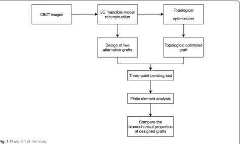
CBCT has been widely used in treatment planning and diagnosis in implant dentistry [34–37]. Digital image data were obtained through a cone beam CT scanner (120 K 70 mA) with field of view of 23 × 16 cm and voxel size of 0.39 mm from a 50-year-old edentulous patient without any pathological condition in the mandible. A total of 512 images were saved as DICOM data files. Figure 1 shows the flowchart of this study.
A platform MIMICS (V16.0, Materialise, Belgium) was used to construct the 3D mandible based on the DICOM data files. The reconstruction procedure was as follows: first, a threshold for bony tissue segmentation was deter-mined from the Hounsfield unit (HU) value and bound-ary. The mandible was separated as a sole mask through ROI (region of interest) extraction. Based on the mask, a 3D model represented as triangular mesh (also known as STL file) was created. Figure2shows the 3D model of the reconstructed mandible.
Material properties of mandible
Because of various degree of calcification of the man-dible, different parts of the mandible have different elas-tic moduli and Poisson’s ratio. Therefore, a mandibular model should be treated as an inhomogeneous material. Calculations of elastic modulus of bone in relation to
bone mass density and Hounsfield unit are expressed in the following equations [38]:
ρ¼114þ0:756HU ð1Þ
E¼0:51ρ1:37 ð2Þ
Fig. 1Flowchart of the study
where, ρ is the density,HUis the Hounsfield unit.;E is the modulus of elasticity.
Mandibular graft design
The models with high-quality volume meshes was exported as Abaqus file (.inp) for topological optimization. To com-pare the performance of the PLA printed grafts with ori-ginal mandible, the bone material properties were also imported to Abaqus for FEA study. The reconstructed model was first split into two parts, shell and core, as shown in Fig.3.
The shell was to maintain the original shape of the jawbone, and the thickness was set to 1.5 mm. The core was designed by topological optimization in Abaqus to form porous scaffold structure. Topology optimization is a mathematical method, which can optimize material layout and maximize system per-formance under given conditions. The mathematical model of the topological optimization can be expressed as:
Find:
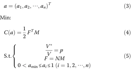
a¼ða1;a2;⋯;anÞT ð3Þ
Min:
C að Þ ¼1 2F
TM ð4Þ
S:t:
V V ¼p F¼NM
0<amin≤ai≤1ði¼1;2;⋯;nÞ
8 > < >
: ð5Þ
where, ai is design variable whose value is continuous between (amin, 1) (amin is a non-zero value to avoid
singularity);nis the number of optimum design variable; C(a)is the global strain energy of the structure;Fis the global vector of structural force; M is the global vector of structure displacement; Vand V* are the volume of structure before and after optimization; p is the pre-scribed volume fraction; Nis the global stiffness matrix of the structure.
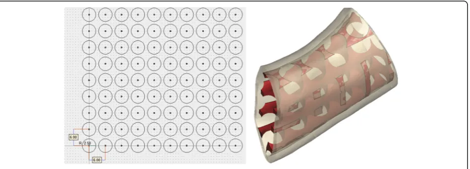
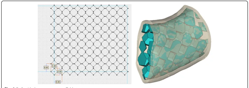
The design of mandibular graft is shown in Fig.4. This study provided other two designed grafts with porous scaffold structure for comparison [39–42]. The porous scaffold structure contained distinct mesh con-figurations and a highly interconnected macroporous network. The macroporous structures were aligned with same intervals without going through the topology optimization process. Figure 5 shows the graft with round-pore struts. The radius of the circle was 2.5 mm, and the distance between adjacent circle centers was 6 mm. Figure 6 shows the graft with square-pore struts. The square diagonal was 5 mm, and the distance be-tween adjacent square centers was 6 mm.
3D printing and anisotropic constitutive model
Grafts in this study were fabricated using an FDM 3D printer with a 210 × 150 × 100 mm build space (CEL Robox, UK). The grafts were fabricated layer-by-layer deposition of molten PLA material via FDM method. Each layer solidified at different intervals. The bond-ing between layers is relatively weaker than the ma-terial itself, causing the variation in the uniaxial tension strength with directions and anisotropic be-havior. This study considered the effect of anisotropy of material on the mechanical behavior of graft, and proposed a constitutive model, which is expressed as follow:
ε11 ε22 ε33 γ12 γ13 γ23 2 6 6 6 6 6 6 4 3 7 7 7 7 7 7 5 ¼ 1 E1 −
v21
E1 −
v31
E3
0 0 0
−v12
E1
1 E1 −
v32
E3
0 0 0
−v13
E1 −
v23
E1
1 E3
0 0 0
0 0 0 1
G12
0 0
0 0 0 0 1
G13
0
0 0 0 0 0 1
G23 2 6 6 6 6 6 6 6 6 6 6 6 6 6 6 6 6 6 4 3 7 7 7 7 7 7 7 7 7 7 7 7 7 7 7 7 7 5 σ11 σ22 σ33 τ12 τ13 τ23 2 6 6 6 6 6 6 4 3 7 7 7 7 7 7 5
ð6Þ
where,1, 2 and 3 are the principal axes directions; ɛ is the normal strain;γ is the shear strain; σ is the normal stress; τ is the shear stress;E is the Young’s modulus;v
is the Poisson’s ratio; G is the shear modulus of the material.
The Young’s and shear moduli of the two perpendicular directions, and the corresponding Poisson’s ratios are the same. Thus, the material comes close to being a trans-versely isotropic material. Transverse isotropy is a special subclass of orthotropic and characterized by a plane of isotropy at every point in the material. Assuming 1–2 plane is the plane of isotropy at every point, transverse isotropy requiresE1=E2=Ep,v31=v32=vtp,v13=v23=vpt,
G13=G23=Gt, where p and t stand for “in-plane” and
“transverse,”respectively. Thus,vtphas the physical inter-pretation of the Poisson’s ratio that characterizes the strain in the plane of isotropy resulting from stress normal to it. vptcharacterizes the transverse strain in the direction nor-mal to the plane of isotropy resulting from stress in the plane of isotropy. The stress-strain laws reduce to
ε11 ε22 ε33 γ12 γ13 γ23 2 6 6 6 6 6 6 4 3 7 7 7 7 7 7 5 ¼ 1 Ep −
vp
Ep −
vtp
Et
0 0 0
−vp
Ep
1 Ep −
vtp
Et
0 0 0
−vpt
Ep −
vpt
Et
1 E3
0 0 0
0 0 0 1
Gp
0 0
0 0 0 0 1
Gt
0
0 0 0 0 0 1
Gt 2 6 6 6 6 6 6 6 6 6 6 6 6 6 6 6 6 6 6 4 3 7 7 7 7 7 7 7 7 7 7 7 7 7 7 7 7 7 7 5 σ11 σ22 σ33 τ12 τ13 τ23 2 6 6 6 6 6 6 4 3 7 7 7 7 7 7 5
ð7Þ
where
Gp ¼Ep=2 1þvp
:
The total number of independent parameters was only five. These parameters were obtained by designing a three-point bending test of 3D printed beam specimens. Fig. 4Graft with topological optimized-pore scaffold structure
To evaluate the effect of printing direction on mechan-ical behavior, all three designed graft models were imported into the 3D printer by STL file format and printed with 0, 45 and 90 degrees orientations with PLA material. Figure7shows the graft models with dif-ferent printing angle. The nozzle diameter was set as 0.4 mm while the layer thickness was set as 0.1 mm. Ac-cording to the printed specimens, the resolution of the printer was sufficient to print the designed microstruc-ture of the graft. Some post-processing such as polish, cutting and support removing were also conducted.
Three-point-bending test
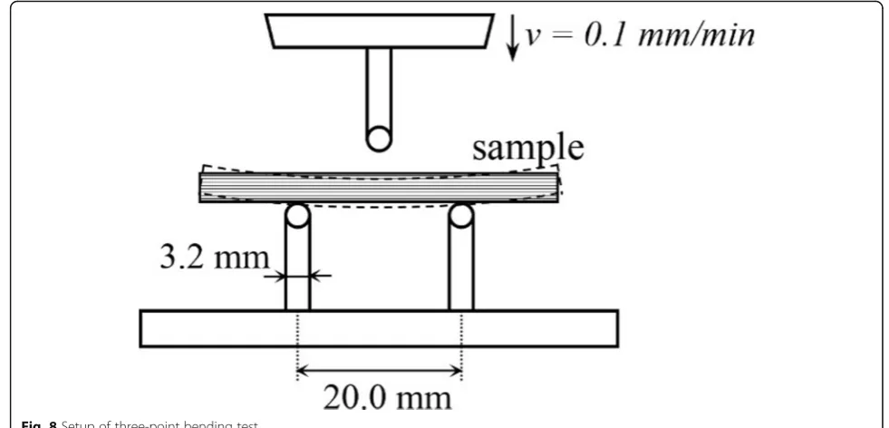
A three-point-bending jig was used to evaluate mech-anical behaviors of the printed beams. The setup of the three-point bending test is shown in Fig. 8. The
lower support spans were 20 mm apart and the upper loading nose was set an equal distance from each span. Two supporting rods and the loading nose had the same radius of 3.2 mm. 0.1 mm/min was set for the loading velocity.
The beam specimens with different printing angle 0°, 45° and 90° were tested. The 0-degree specimens had printing angle perpendicular to the loading cross-section; the 45-degree specimens had a 45° angle between loading cross-section and printing direction, and the 90-degree specimens had a printing angle parallel to the loading sec-tion. Three duplicate specimens were prepared for each printing angle with the same dimension. The dimensions were 30 mm × 10 mm × 5 mm. The mid-span flexural stress and strain were calculated according to formulas provided by ASTM standard [43].
Fig. 6Graft with the square-pore scaffold structure
σf ¼
3PL
2bd2 ð8Þ
εf ¼
6Dd
L2 ð9Þ
where,σfis the flexural stress;Pis the load at the center of the beam; L is the support span; b is the width of beam tested;d is the depth of beam tested;ɛfis sample strain;Dis the deflection at the center of the beam.
In addition to the beam samples, the effect of printing angle (00, 450and 900) of grafts on mechanical strength was also evaluated by a three-point bending test. Four grafts of each printing type were prepared and tested. Maximum load, field load, failure deflection and yield deflection were measured and the biomechanical behav-ior of each group was compared.
Finite element analysis
FEA calculations are based on finite element models that allow the validation of the experimental observations and calibrate the constitutive relationship between virtual and physical models [44]. The FE models were built with the material parameters obtained from the three-point bending test described in 2.5 using Abaqus. The transverse aniso-tropic material models were used with the principal axis set based on the printing directions. The digital grafts with dif-ferent printing directions were subjected to loads corre-sponding to the three-point bending test. The initialization and propagation of cracks at the bottom were modeled with the extended finite element method (XFEM). The schematic setup of grafts subjected to loading is shown in
Fig. 9. The mechanical responses were obtained from the computational simulations.
Results
Three-point-bending test of beam specimens
Experimental data of the three-point bending test on beams were summarized in Fig. 10. The results show good repeatability of samples in the same group. The yield stress, failure stress, failure strain, ultimate strength and flexural modulus were calculated for each sample to better understand the mechanical performance of the printed material. The yield stress was calculated using the method of 0.2% offset; failure stress corresponds to the stress at failure strain, ultimate strength obtained from the maximum stress value. Flexural modulus was along the linear portion of the stress-strain curve. All these five properties were evaluated for each printed graft. The average value and standard deviation of each group are summarized in Table1. Figure11shows a typ-ical failure mode and crack distribution of beam speci-mens from each group.
Based on the experimental results and computational model calibration, the following values of mechanical pa-rameters were obtained for the anisotropic constitutive model (in the printing plane:E1=E2= 1590MPa, G12=
722MPa, perpendicular to the printing plane:E3= 2050
MPa,G23=G13= 560MPa,v12=v13=v23= 0.42.).
The three-point bending test of grafts
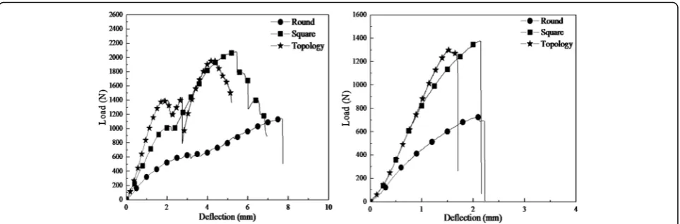
The results of three-point bending test from different types of printed grafts are summarized in Fig. 12. The
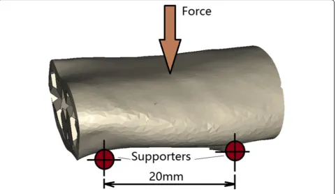
Fig. 9Setup of grafts subjected to three-point bending load
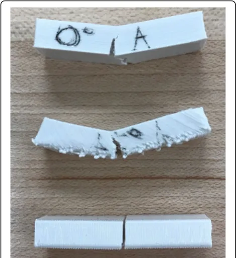
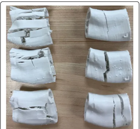
with round-pore internal structure, square-pore struc-ture, and topological optimized-pore internal strucstruc-ture, respectively. The effect of printing angle on mechanical behavior of maximum load, yield load, failure deflection and yield deflection were calculated and compared for each group, as shown in Fig. 13. Figure 14 shows the failure mode and crack propagation of different grafts printed with 0 and 90 degree angles. Three grafts on the left in Fig.14are the 0-degree printed samples while the three right samples were printed at 90-degree.
The finite element analysis of grafts
Figure15is the cross-sectional FEA results, which pro-vide detailed information on maximum displacement, and Von Mises stress distribution of the three porous structures of grafts. For each graft, the left side displays the maximum displacement near the loading nose loca-tion and the global maximum displacement spot. The right side graph displays the Von Mises stress distribu-tion. Since the anisotropic constitutive model proposed in this study is based on the linear-perfect plastic model
which is insufficient to capture the plastic stage and large deformation, all computational models were sub-jected to a 500 N three-point bending load that repre-sents maximum chewing force from patients.
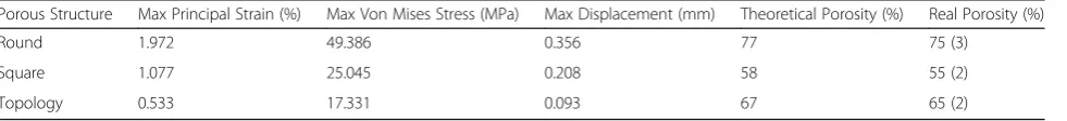
Table 2lists the maximum principal strain, maximum Von Mises stress, maximum displacement and porosity of each design of graft. Porosity is a measure of the void spaces in a graft and is a fraction of the volume of voids over the total volume based on the reconstructed man-dibular core scaffold. Porosity can be theoretically calcu-lated from the 3D computational model and real porosity can be calculated from printed graft using Archimedes principle that the volume of displaced water is equal to the volume of the submerged object. When printing some models with spatial structure, like graft in this case, the printer will generate some supports to avoid structural collapse, and some supports are difficult to remove after printing. Therefore, the printed porosity is often slight smaller than designed porosity. However, the error in this study is below 5%, which is acceptable.
Discussion
PLA has not been currently used as bone analogs for mandibular reconstruction surgery in load-bearing areas. Its excellent biocompatibility and biodegradation proper-ties are important reason for extensively studied in the lit-erature as a scaffolding material for tissue engineering in craniofacial areas. Further strategies to improve its mech-anical properties based on PLA modifications and PLA nanocomposite designs may be the key to improve its mechanical properties for mandibular reconstruction. This project is to provide valid information for readers to understand mechanical issues of 3D printed biomaterials.
Comparison of 3D printed beams with different printing angles
The load-deflection curves of Fig. 10 from three-point bending test validate that the direction of printing angle has a substantial effect on the mechanical properties of 3D printed parts. From the load-deflection curves of beam printed at 0-degree angle, the beam showed its elastic property in the initial loading stage. With the load increased, the beam entered the plastic stage, and plastic strain developed and cracked until global damage. The similar trend was observed from the load-deflection curves of beam printed at 45-degree angle. However, the
Table 1Flexural properties of PLA beam specimens with three printing conditions
Printing Angle (degree) Ultimate Strength (MPa) Yield Strength (MPa) Failure Strength (MPa) Failure Strain (%) Flexural Modulus (GPa)
0 107.98 (7.13)a 94.68 (7.90) 96.60 (10.00) 7.36 (0.34) 2.06 (0.08)
45 71.53 (3.45) 69.70 (3.73) 68.26 (2.80) 5.77 (0.47) 1.21 (0.03)
90 49.20 (1.71) 49.20 (1.71) 49.20 (1.71) 2.82 (0.08) 1.59 (0.07)
a
Values in parentheses are the standard deviations of each group
Fig. 12Load-deflection curves of three-point bending test on grafts printed at 0-degree (left) and 90-degree (right)
load-deflection curve for beam specimen printed at 90-degree angle doesn’t show apparent yield or horizon-tal segment. After reaching the peak point, the crack propagates suddenly penetrated through the whole cross-section and the beam fractured into two parts. This is different from the flexural curves for the speci-mens printed at 0-degree or 45-degree angles, which show slight plastic failure before their rupture occurred.
Figure 11 shows the beam specimens with 0-degree printing angle presents flexural failure and the main cracks appeared in the mid-span and prorogated along the middle axis. The same failure mode can be seen in the beam specimens printed at 45-degree angle with cracks grew along 45-degree printing direction. For the beam specimens printed at 90-degree angle, it presents shear failure with the shear force exceeded the bond strength between the layers. The local failure and global failure occurred at a similar load. The beam was sheared off in the middle of the beam where the highest stress was concentrated.
The data from the three-point bending test of PLA (Table 1) also illustrate that all of the properties exhibit anisotropic behavior with property differences up to 60%. The average ultimate strength of a specimen printed at 0-degree was 54% higher than that of a speci-men printed at 90-degree and 34% higher than that of those specimens printed at 45-degree. Similar patterns occurred on the failure stress and yield strength among those three groups. Furthermore, the average strain at failure was almost 2.5 times for the specimen printed at 0-degree than that printed at 90-degree and was also
14% higher than that printed at 45-degree. There was a great effect of printing direction on flexural modulus shown in Table1. Flexural modulus values of specimens printed at 0-degree were 23% higher than that printed at 90-degree and 41% higher than specimens printed at 45-degree. Overall, beam specimens printed at 0-degree clearly performed the best among the three groups.
Comparison of 3D printed grafts with different printing angles
The load-deflection curves from three-point bending test (Fig. 12) illustrate anisotropic behavior of printed grafts. Similar mechanical behavior trends are observed, i.e., elastic and plastic deformation, of grafts based on print-ing directions. The data of flexural properties for grafts (Fig. 13) show that the maximum load of each graft printed at 0-degree is much higher than that of 90-degree printed with differences up to 72%. The aver-age failure deflection of grafts printed at 0-degree was much higher than that of 90-degree printed with differ-ences up to 73%. The yield load and deflection are not significantly affected by printing angle. By combining the experimental data and failure mode of grafts, it is found that for grafts printed at 0-degree, local failure started from upper filament layers, the propagation of cracks was perpendicular to the direction of loading. As the de-flection increased, the tensile force between the bottom filament layers exceeded the bond strength; the crack opening began to grow along the printing direction until the global failure occurred. On the contrast, for grafts printed at 90-degree, local failure began from the upper filament and then propagated along the loading direc-tion, the global failure occurred at almost the same time since the bonding between the adjacent filaments was weak, and the cracks could easily penetrate through the whole filament layers. It explains why the direction of main crack propagation in Fig. 14 are different from grafts printed with 00and 900. Also, it matches with the obtained results that the maximum load and deflection for grafts printed with 00are much higher than that of grafts printed with 900.
Comparison of the topological optimized graft with other designed grafts
The results of the finite element analysis of mechanical behaviors of the printed grafts are presented in Table2. The maximum principal strain (%), Von Mises stress (MPa), and displacement (mm) of the topological opti-mized grafts decreases 73%, 65%, and 74% respectively when compared to those with round-pore structure de-sign. Comparing to the square-pore structure, the opti-mized structure has a decrease of 51% in maximum principal strain, 31% in maximum stress, and 55% in dis-placement. The maximum Von Mises stress distribution Fig. 14Comparison of failed grafts with round-pore, square-pore
of grafts (Fig. 15) indicates that the stresses are always concentrated at the top aspect of the graft. The same pattern is observed with maximum displacement. The topological optimized graft has significantly better re-sults as most of the meshes keep very small stress and the maximum stress is well below the allowable stress (σ= 90 MPa). In order to compare the mechanical be-havior of designed grafts with human natural mandible, the model of original structure of the mandible was built with the material parameters obtained from the CBCT files described in 2.2 under using Abaqus. The max-imum principal strain, maxmax-imum Von Mises stress, and
maximum displacement of original mandible model are 0.232%, 15.427 MPa, and 0.090 mm respectively. The topological optimized graft has the mechanical proper-ties close to the real bone in terms of the maximum Von Mises stress and maximum displacement. The maximum principal strain of the optimized graft is slightly higher than that of the human mandible, which may be led by the difference of Young’s modulus and density between the bone and PLA material. The average Young’s modu-lus and density of bone in this patient are 10GPa and 1500 kg/m3, which is much higher than that of the PLA materials with 2GPa and 1200 kg/m3. However, the Fig. 15FEA results of grafts.a. Round-pore.b. Square-pore.c. Topological optimized-pore internal scaffold
Table 2Flexural properties for the PLA grafts
Porous Structure Max Principal Strain (%) Max Von Mises Stress (MPa) Max Displacement (mm) Theoretical Porosity (%) Real Porosity (%)
Round 1.972 49.386 0.356 77 75 (3)
Square 1.077 25.045 0.208 58 55 (2)
Topology 0.533 17.331 0.093 67 65 (2)
a
mechanical properties of the other two designed grafts are relatively poor, which cannot provide a good envir-onment for defect repair in clinic.
The real porosity (%) of the topological optimized graft is 65, which increases 15% when compared to the grafts with square-pore structure. Although the porosity of topological optimized graft is lower than graft with round-pore scaffold structure, the strength and stiffness are significantly improved. The results verify that the topological optimization method is capable of optimizing the grafts by assigning more strut elements to the stress concentration area and removing strut elements from the low-stress area. In this way, graft can have higher space utilization, higher strength and stability, and more uniform stress distribution. However, these two conven-tional grafts use uniform configuration of strut elements, which can cause stress concentration and material waste. Overall, the printed graft designed by topological optimization method provides high strength, stiffness, and porosity that can provide a conducive environment from mechanical and biological perspectives.
Conclusions
A new method of restoring segmental bony defects of the mandible to its exact original shape, size and form is proposed by using 3D printing technology and topological optimization method. 3D printing technology can easily fabricate complex shapes to match patients’ unique de-fects. The 3D printed graft samples had anisotropic prop-erties. Printing direction and internal design of the grafts significantly affected their mechanical properties. The grafts printed at 0° with topology optimization had the best results. Although the results of this study are based on PLA material, the proposed methodologies are also ap-plicable to other promising 3D printing materials such as Polyetheretherketone (PEEK). 3D printing technology and topological optimization are useful tools in fabrication and designing bone analogs for mandibular reconstruction.
Abbreviations
ABS:Acrylonitrile butadiene styrene; CBCT: Cone beam computed tomography; FDM: Fused deposition modeling; FEM: Finite element modeling; PLA: Polylactic Acid
Acknowledgements
The James Hayward Research Fund funds the article processing charge for this publication.
Funding
The project is partially supported by the James Hayward Research Fund.
Availability of data and materials
Readers interested in data should contact the authors.
Authors’contributions
JH conducted experiments, collected data and drat the manuscript; JHW conceived the study, interpret the data and revised the manuscript; RW: designed the study and interpreted the data; YL, XY, and DAB: edited the manuscript. All authors read and approved the final manuscript.
Ethics approval and consent to participate Not applicable.
Consent for publication
Informed consent was obtained from all individual participants included in the study.
Competing interests
The authors declare that they have no competing interests.
Publisher’s note
Springer Nature remains neutral with regard to jurisdictional claims in published maps and institutional affiliations.
Author details 1
Department of Electrical Engineering and Computer Science, Case Western Reserve University School of Engineering, Cleveland, OH 44106-7201, USA. 2Department of Orthopedic Surgery, Case Medical Center, Cleveland, OH
44106, USA.3Department of Comprehensive Care, Case Western Reserve University School of Dental Medicine, Cleveland, OH, USA.4Department of Civil Engineering, Case Western Reserve University School of Engineering, Cleveland, OH 44106-7201, USA.5Key Laboratory of E&M (Zhejiang University of Technology), Ministry of Education & Zhejiang Province, Hangzhou 310014, Zhejiang Province, China.6Department of Maxillofacial Surgery, Case Western Reserve University School of Dental Medicine, Cleveland, OH 44106, USA.
Received: 24 August 2018 Accepted: 19 February 2019
References
1. Dendrinos G, Kontos S, Lyritsis E. Use of the Ilizarov technique for treatment of non-union of the tibia associated with infection. JBJS. 1995;77(6):835–46. 2. Chadayammuri V, Hake M, Mauffrey C. Innovative strategies for the
management of long bone infection: a review of the Masquelet technique. Patient safety in surgery. 2015;9(1):32.
3. Zorn K. Segmental tibial defects. Comparing conventional and Ilizarov methodologies. Clinical orthopaedics and related research. 1994;301:118–23. 4. Eshraghi S, Das S. Mechanical and microstructural properties of
polycaprolactone scaffolds with one-dimensional, two-dimensional, and three-dimensional orthogonally oriented porous architectures produced by selective laser sintering. Acta Biomater. 2010;6(7):2467–76.https://doi.org/10. 1016/j.actbio.2010.02.002.
5. Marcos-Campos I, et al. Bone scaffold architecture modulates the development of mineralized bone matrix by human embryonic stem cells. Biomaterials. 2012;33(33):8329–42.https://doi.org/10.1016/j.biomaterials.2012.08.013. 6. Syahrom A, et al. Permeability studies of artificial and natural cancellous
bone structures. Med Eng Phys. 2013;35(6):792–9.https://doi.org/10.1016/j. medengphy.2012.08.011.
7. Rajagopalan S, Robb RA. Schwarz meets Schwann: design and fabrication of biomorphic and durataxic tissue engineering scaffolds. Med Image Anal. 2006;10(5):693–712.https://doi.org/10.1016/j.media.2006.06.001. 8. Voronov R, et al. Computational modeling of flow-induced shear stresses
within 3D salt-leached porous scaffolds imaged via micro-CT. J Biomech. 2010;43(7):1279–86.https://doi.org/10.1016/j.jbiomech.2010.01.007. 9. Chana JS, et al. Segmental mandibulectomy and immediate free fibula
osteoseptocutaneous flap reconstruction with endosteal implants: an ideal treatment method for mandibular ameloblastoma. Plast Reconstr Surg. 2004;113(1):80–7.https://doi.org/10.1097/01.PRS.0000097719.69616.29. 10. Gbara A, et al. Long-term results of jaw reconstruction with microsurgical
fibula grafts and dental implants. J Oral Maxillofac Surg. 2007;65(5):1005–9. https://doi.org/10.1016/j.joms.2006.06.294.
11. Wang R, et al. Effect of interfragmentary gap on the mechanical behavior of mandibular angle fracture with three fixation designs: a finite element analysis. J Plast Reconstr Aesthet Surg. 2017;70(3):360–9.https://doi.org/10. 1016/j.bjps.2016.10.026.
12. Ferri J, et al. Advantages and limitations of the fibula free flap in mandibular reconstruction. J Oral Maxillofac Surg. 1997;55(5):440–8.https://doi.org/10. 1016/S0278-2391(97)90685-6.
pilot study. The International Journal of Medical Robotics and Computer Assisted Surgery. 2012;8(2):215–20.https://doi.org/10.1002/rcs.456. 14. Montazerian H, et al. Porous scaffold internal architecture design based on
minimal surfaces: a compromise between permeability and elastic properties. Mater Des. 2017;126:98–114.https://doi.org/10.1016/j.matdes. 2017.04.009.
15. Pobloth A-M, et al.Mechanobiologically optimized 3D titanium-mesh scaffolds enhance bone regeneration in critical segmental defects in sheep. Science translational medicine. 2018;10(423):eaam8828.https://doi.org/10.1126/ scitranslmed.aam8828.
16. Ahn S-H, et al. Anisotropic material properties of fused deposition modeling ABS. Rapid Prototyp J. 2002;8(4):248–57.https://doi.org/10.1108/
13552540210441166.
17. Masood S, Song W. Development of new metal/polymer materials for rapid tooling using fused deposition modelling. Mater Des. 2004;25(7):587–94. https://doi.org/10.1016/j.matdes.2004.02.009.
18. Lee Y-B, et al. Bio-printing of collagen and VEGF-releasing fibrin gel scaffolds for neural stem cell culture. Exp Neurol. 2010;223(2):645–52.https://doi.org/ 10.1016/j.expneurol.2010.02.014.
19. Murphy SV, Skardal A, Atala A. Evaluation of hydrogels for bio-printing applications. J Biomed Mater Res A. 2013;101(1):272–84.https://doi.org/10. 1002/jbm.a.34326.
20. Schieker M, et al. Biomaterials as scaffold for bone tissue engineering. European journal of trauma. 2006;32(2):114–24.https://doi.org/10.1007/ s00068-006-6047-8.
21. Yang S, et al. The design of scaffolds for use in tissue engineering. Part I. Traditional factors. Tissue Eng. 2001;7(6):679–89.https://doi.org/10.1089/ 107632701753337645.
22. Habibovic P, et al. Osteoconduction and osteoinduction of low-temperature 3D printed bioceramic implants. Biomaterials. 2008;29(7):944–53.https://doi. org/10.1016/j.biomaterials.2007.10.023.
23. Es-Said O, et al. Effect of layer orientation on mechanical properties of rapid prototyped samples. Mater Manuf Process. 2000;15(1):107–22.https://doi. org/10.1080/10426910008912976.
24. Bellini A, Güçeri S. Mechanical characterization of parts fabricated using fused deposition modeling. Rapid Prototyp J. 2003;9(4):252–64.https://doi. org/10.1108/13552540310489631.
25. Hill N, Haghi M. Deposition direction-dependent failure criteria for fused deposition modeling polycarbonate. Rapid Prototyp J. 2014;20(3):221–7. https://doi.org/10.1108/RPJ-04-2013-0039.
26. Lee C, et al. Measurement of anisotropic compressive strength of rapid prototyping parts. J Mater Process Technol. 2007;187:627–30. 27. Shum HC, Kim J-W, Weitz DA. Microfluidic fabrication of monodisperse
biocompatible and biodegradable polymersomes with controlled permeability. J Am Chem Soc. 2008;130(29):9543–9.https://doi.org/10.1021/ ja802157y.
28. Rosenzweig DH, et al. 3D-printed ABS and PLA scaffolds for cartilage and nucleus pulposus tissue regeneration. Int J Mol Sci. 2015;16(7):15118–35. https://doi.org/10.3390/ijms160715118.
29. Anderson JM, Shive MS. Biodegradation and biocompatibility of PLA and PLGA microspheres. Adv Drug Deliv Rev. 1997;28(1):5–24.https://doi.org/10. 1016/S0169-409X(97)00048-3.
30. Hollister SJ, Maddox R, Taboas JM. Optimal design and fabrication of scaffolds to mimic tissue properties and satisfy biological constraints. Biomaterials. 2002;23(20):4095–103. https://doi.org/10.1016/S0142-9612(02)00148-5.
31. Kang H, Lin C-Y, Hollister SJ. Topology optimization of three dimensional tissue engineering scaffold architectures for prescribed bulk modulus and diffusivity. Struct Multidiscip Optim. 2010;42(4):633–44.https://doi.org/10. 1007/s00158-010-0508-8.
32. Lin CY, Kikuchi N, Hollister SJ. A novel method for biomaterial scaffold internal architecture design to match bone elastic properties with desired porosity. J Biomech. 2004;37(5):623–36.https://doi.org/10.1016/j.jbiomech. 2003.09.029.
33. Liu Y-F, et al.A customized fixation plate with novel structure designed by topological optimization for mandibular angle fracture based on finite element analysis. Biomedical engineering online. 2017;16(1):131.
34. Cohen A, et al. Mandibular reconstruction using stereolithographic 3-dimensional printing modeling technology. Oral Surgery, Oral Medicine, Oral Pathology, Oral Radiology, and Endodontology. 2009;108(5):661–6. https://doi.org/10.1016/j.tripleo.2009.05.023.
35. Ludlow JB, et al. Dosimetry of 3 CBCT devices for oral and maxillofacial radiology: CB Mercuray, NewTom 3G and i-CAT. Dentomaxillofacial Radiology. 2006;35(4):219–26.https://doi.org/10.1259/dmfr/14340323. 36. Ludlow JB, Ivanovic M. Comparative dosimetry of dental CBCT devices and
64-slice CT for oral and maxillofacial radiology. Oral Surgery, Oral Medicine, Oral Pathology, Oral Radiology, and Endodontology. 2008;106(1):106–14. https://doi.org/10.1016/j.tripleo.2008.03.018.
37. Abdullah JY, et al.Comparison of 3D reconstruction of mandible for pre-operative planning using commercial and open-source software. InAIP Conference Proceedings. 2016. AIP Publishing.
38. Liu Y-F, et al. Digital design and fabrication of simulation model for measuring orthodontic force. Biomed Mater Eng. 2014;24(6):2265–71. https://doi.org/10.3233/BME-141039.
39. Drury JL, Mooney DJ. Hydrogels for tissue engineering: scaffold design variables and applications. Biomaterials. 2003;24(24):4337–51.https://doi.org/ 10.1016/S0142-9612(03)00340-5.
40. Hollister SJ. Porous scaffold design for tissue engineering. Nat Mater. 2005; 4(7):518.https://doi.org/10.1038/nmat1421.
41. Hutmacher, D.W,Scaffolds in tissue engineering bone and cartilage, inThe Biomaterials: Silver Jubilee Compendium. 2006, Elsevier. p. 175–189, DOI: https://doi.org/10.1158/2326-6066.CIR-18-0566.
42. Yoshimoto H, et al. A biodegradable nanofiber scaffold by electrospinning and its potential for bone tissue engineering. Biomaterials. 2003;24(12): 2077–82.https://doi.org/10.1016/S0142-9612(02)00635-X.
43. Astm I. Standard test methods for flexural properties of unreinforced and reinforced plastics and electrical insulating materials. ASTM. 2007;D790-07. 44. Viceconti M, et al. Extracting clinically relevant data from finite element