R E S E A R C H A R T I C L E
Open Access
Testing the adaptive value of gastropod
shell morphology to flow: a
multidisciplinary approach based on
morphometrics, computational fluid
dynamics and a flow tank experiment
Gerlien Verhaegen
1*, Hendrik Herzog
2, Katrin Korsch
3, Gerald Kerth
3, Martin Brede
4and Martin Haase
1Abstract
A major question in stream ecology is how invertebrates cope with flow. In aquatic gastropods, typically, larger and more globular shells with larger apertures are found in lotic (flowing water) versus lentic (stagnant water) habitats. This has been hypothetically linked to a larger foot, and thus attachment area, which has been suggested to be an adaptation against risk of dislodgement by current. Empirical evidence for this is scarce. Furthermore, these previous studies did not discuss the unavoidable increase in drag forces experienced by the snails as a
consequence of the increased cross sectional area. Here, usingPotamopyrgus antipodarumas a study model, we
integrated computational fluid dynamics simulations and a flow tank experiment with living snails to test whether 1) globular shell morphs are an adaptation against dislodgement through lift rather than drag forces, and 2) dislocation velocity is positively linked to foot size, and that the latter can be predicted by shell morphology. The drag forces experienced by the shells were always stronger compared to the lift and lateral forces. Drag and lift forces increased with shell height but not with globularity. Rotating the shells out of the flow direction increased the drag forces, but decreased lift. Our hypothesis that the controversial presence of globular shells in lotic environments could be explained by an adaptation against lift rather than drag forces was rejected. The foot size was only predicted by the size of the shell, not by shell shape or aperture size, showing that the assumed aperture/ foot area correlation should be used with caution and cannot be generalized for all aquatic gastropod species. Finally, shell morphology and foot size were not related to the dislodgement speed in our flow tank experiment. We conclude that other traits must play a major role in decreasing dislodgement risk in stream gastropods, e.g., specific behaviours or pedal mucus stickiness. Although we did not find globular shells to be adaptations for reducing dislodgement risk, we cannot rule out that they are still flow-related adaptations. For instance, globular shells are more crush-resistant and therefore perhaps adaptive in terms of diminishing damage caused by tumbling after dislodgement or against lotic crush-type predators.
Keywords:Potamopyrgus antipodarum, Computational fluid dynamics, Flow tank, Morphology, Adaptation, Gastropod
* Correspondence:[email protected]; [email protected]
1Vogelwarte, Zoologisches Institut und Museum, Universität Greifswald,
Soldmannstraße 23, 17489 Greifswald, Germany
Full list of author information is available at the end of the article
Background
A major question in stream ecology is how invertebrates cope with flow [1]. It is indeed long known that many stream species avoid exposing themselves to flow [2] or exhibit morphological adaptations when compared to len-tic (i.e. stagnant waters) species (e.g. [1,3]). The main se-lective pressures involved in adaptation to flow were later identified to be 1) drag and 2) lift forces, 3) corrasion, and 4) diffusion through boundary layers [4]. Drag (FD) (Eq.1)
is the force acting on an object due to the impingement of the fluid, while lift (FL) (Eq.2) is the vertical force acting
perpendicularly to the relative flow direction resulting in a difference of pressures on opposites sides of the object. Both forces are defined as follows:
FD¼CDρA v2
2 ð1Þ
FL¼CLρA v2
2 ð2Þ
withCDbeing the drag coefficient,ρthe fluid density, A
the projected frontal surface area of the object,Vthe vel-ocity (object speed relative to flow speed), andCLthe lift
coefficient.CDis composed of the effects of skin friction
drag, i.e. the drag depending on the smoothness of the surface of an object, and form drag, i.e. the drag depend-ing on the shape of the object. High drag and lift can impede the active movement of stream living organisms and increase dislodgement risk. While it is difficult to assess the biological significance of the energy costs for organisms to counter drag (e.g. [5]), it is undisputed that dislodgement can lead to physical damage and may redeposit organisms to less suitable habitats (e.g., [6]), although little is known about the fate of organisms once carried away. The third selective pressure, corrasion, is defined as the risk of abrasion through suspended solids [7]. In contrast to these risk-increasing factors, the diffu-sive exchange processes of e.g. gas or ions through the thinner boundary layers are usually enhanced in lotic (i.e. flowing water) versus lentic habitats and thus are a positive factor of living in streams.
These four selective pressures all depend on the inter-play between the fluid properties and the shape and size of the organisms. As a result, disentangling their relative significance in the morphological adaptation of organisms to flow is a complex matter. For instance, Weissenberger et al. [8] showed striking differences in the relative import-ance of drag and lift forces across different species of may-flies and stonemay-flies studying living larvae in a flow tank at equal velocities. Furthermore, morphologies favouring flow separation, i.e. the detachment of flow from the body surface of the organisms, would on the one hand decrease corrasion risk, but on the other hand would also nega-tively influence the diffusive exchange processes as
the water renewal near the body surface would decrease as well [4]. Thus, organisms cannot simultaneously optimize their morphology with respect to all four select-ive pressures. The final morphology will necessarily be the result of evolutionary trade-offs.
In the last decades, stream ecology has benefitted from technological innovations and improved measurement methods, although this has also revealed the complexity of hydrodynamic adaptation, making generalizations for the diversity of invertebrates difficult [1]. Shells of aquatic gastropods are ideal objects to study adaptation to flow as these hard structures are permanently exposed to their liquid environment. Typically, larger and wider but shorter (globular) shells with larger apertures are found in lotic versus lentic habitats (e.g. inBellamya spp. [9],Radix labiata(asLymnaea peregra[10]),Lithasiaspp. [11,12], andElimia potosiensis[13]).
It is commonly suggested that a larger aperture in gastropods, associated with a larger foot and thus attach-ment area, is an adaptation against risk of dislodgeattach-ment by current (e.g. [14]). Empirical evidence for this is scarce, though. Increased adhesion due to larger aper-ture and foot size was shown e.g. for the marine gastropod Nucella lapillus in habitats with higher wave exposure [15]. However, these studies did not discuss the unavoidable increase in drag forces experienced by the snails as a consequence of the increased cross-sec-tional area, thus some of these morphological structures believed to be adaptations to resist water flow may in-crease dislodgement risk, not reduce it. The first attempts to link shell morphology of freshwater snails to dislodgement speed and experienced drag forces were done by the use of flow tanks and Newton meters (e.g. [16–18]). Although drag forces increased with shell size, which had a higher impact on dislodgement speed than foot size, the relationship between shell size and dis-lodgement speed varied highly among species. Laser Doppler Anemometry was later used to investigate velocity gradients around gastropod shells aiming at a better understanding of the relationships between the morphology and drag, lift, corrasion and diffusive exchanges [4].
[31–34]. A number of recent studies have revealed complex interactions between habitat characteristics including flow, shell shape, size, and fitness in this species [22, 23, 35–37]. It appears that flow imposes a number of counteracting selective forces on shell characteristics resulting in evolutionary trade-offs. For example, lower frequencies of spiny snails were found in streams as compared to lakes, presumably because spiny shells tend to collect seston, i.e., matter floating in the water body, increasing the drag of the shell, al-though spines may protect against predation [38]. In this species as well, the typically larger but more globular shell morphology with larger aperture area was found at higher flow rates, the increase in drag being hypothesized to be counterbalanced by a larger foot [22, 23, 36, 37]. However, at higher flow rates, shells with larger aperture areas relative to the shell size as well as snails with relatively slender shells had higher brood sizes, thus seemed better adapted in terms of fitness compared to snails with globular shells. In general, larger snails always showed higher fecundity, although the relationship between size and fecundity was weaker with increasing flow rate in in-vasive as compared to native populations, reflecting again possible trade-offs in exhibiting a larger and globular shell in lotic habitats [22, 23].
In the present study, we sought to better understand the hydrodynamic adaptation of shell morphology in gastropods, using P. antipodarum as study model by integrating computational fluid dynamics (CFD) simu-lations and a flow tank experiment with living snails. Although evolutionary trends are easier to detect at higher taxonomic levels, studying adaptation on the in-traspecific level does not need to consider phylogenetic constraints [39] and is therefore especially well-suited to identify adaptive pressures and provide insights to the microevolutionary mechanisms leading to pheno-typic differentiation [40, 41]. Here, we used the CFD simulations to calculate the relative drag and lift forces of three shell morphologies (globular, intermediate, and slender), and tested the overall hypothesis that shell morphology in gastropods is an adaptation against dislodgement through lift rather than drag forces, the latter inevitably increasing with diameter. This would explain the counterintuitive presence of wider shells with shorter spires in lotic environments. We comple-mented our CFD simulations, which could only test forces on the shells without the presence of the soft body, with a flow tank experiment. Here, we tested the specific hypothesis that the dislocation velocity of living snails is linked to shell morphology and foot size, and that the latter can be predicted by shell morphology, in particular the aperture area as assumed by several authors [22,23,36,37].
Methods
In this study, we combined analyses of behaviour with CFD simulations. We usedμ-CT-scanned mollusc shells to obtain 3D models that were used for CFD simulations to calculate the hydrodynamic forces. The results of these theoretical models were then compared with our behavioural study conducted in a flow tank. In both, nat-urally experienced flow velocities were applied [22,23].
Shell model generation
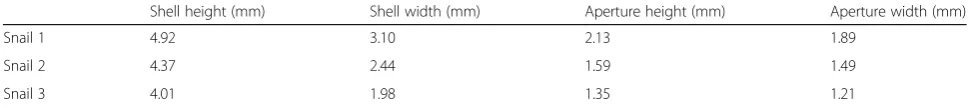
We based our models on three P. antipodarum snails chosen for their distinct shell shapes: snail 1 was short and wide, snail 3 narrow and elongate, and snail 2 had an intermediary shell shape (Table 1). Snail 1 was col-lected from an approximately 8 m-wide river in the Kaniwhaniwha reserve in the Waikato region on New Zealand’s North Island (S 37° 55′ 12.8", E 175° 4’52.9") in February 2016; snail 2 from Lake Kiessee, near Jarmen in Mecklenburg-Western Pomerania in NE Germany (N 53° 55′ 44.5", E 13° 18’ 60.0") in June 2017; and snail 3 from an approx. 1 m-wide river in the northern West Coast region of New Zealand’s South island (S 42° 2′9.3", E 171° 23’21.1") in March 2016. All snails were fixed on site in 70% ethanol. Snails retract upon contact with etha-nol; therefore, our models were based on the shells only.
The three shells were mounted vertically by gluing the
apex onto a pin and scanned with a μCT Xradia
MicroXCT-200 scanner (Carl Zeiss X-ray Microscopy Inc., Pleasanton, USA) at 40 kV, 8 W and at four times magnification. The pixel sizes for the three snail shells were 5.087, 3.981 and 4.031μm, respectively. The image stacks (in TIFF format) were processed and 3D surfaces models constructed with an isosurface threshold of ~ 35,000 with the AMIRA v. 5.6.0 (FEI, Visualization Science Group) software (Fig.1). The final models were exported as a stereolithography (*.stl) file and further processed in the Meshlab software (64-Bit Version 1.3.3 Visual Computing Lab – ISTI – CNR, http://meshlab. sourceforge.net/). In Meshlab, redundant details of the shell, i.e. the inner structures, were removed from the model by ambient occlusion filtering and a new mesh surface was created on the remaining vertices by means of Poisson surface reconstruction. The models were scaled according to real world dimensions by voxel size given by the μCT reconstruction software. These com-pletely closed polygon models contained about 11,000– 16,000 faces (model 1: 12,686; model 2: 16,280; model 3: 11,774), were exported as polygon meshes (*.stl), and then used for the CFD simulation.
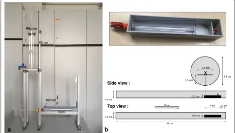
CFD setup
The virtual experiments were conducted in a half-cylin-drical water column (Fig. 2) built in ANSYS ICEM CFD v. 18.0 mimicking the real experimental channel (Fig.3): diameter 14 mm, length 100 mm with a platform at the bottom section. Five shell models were tested in total: shells 1–3 in their original dimensions, and then again shell 2 and 3 scaled to the height of shell 1 (Fig. 1) to compensate for the differences in size between the shells (Table1). The shell models were loaded into the simula-tion environment and placed in comparable posisimula-tion and orientation into the virtual flow channel (Fig. 2). To in-vestigate the influence of the orientation of the snail to the flow, the angle between the main axis of the shell and the main flow direction was altered horizontally anticlockwise (0°, 45° and 90°). For every shell (shell 1, shell 2, shell 3, scaled shell 2 and scaled shell 3) at every orientation, a tetrahedral mesh of the set up was created according to the octree meshing algorithm. After remov-ing the volume mesh of the shell models, the “hollow” meshes were exported as binary (*.cfx5) format. The final meshes are containing approximately 750,000 num-ber of elements.
The created meshes were used for the CFD simula-tions in CFX with a root mean square (RMS) residual target of the equation system of 0.0001 and an incoming water flow velocity of 0.2 m/s (Re = 2793.6). To study how the flow environment around the shells and the lift-on-drag ratio would vary with increasing flow,
simulations for the shell models 1–3 at 0° rotation were repeated at 0.6 m/s (Re = 8380.7) and 1 m/s (Re = 13,967.9), to cover the velocity range of the flow tank ex-periment. The Reynolds numbers (Re) of the flow in the channel and for the shell models in our experimental set-up were calculated based onEq.3:
Re¼uD
v ð3Þ
withDbeing the diameter of the cylinder for the flow in the channel, or the hydraulic diameter (DH) in the
case of the shell models,uthe mean fluid velocity, andν the kinematic viscosity of the fluid (here, ν = 10−6 for water at 20 °C). The Reynolds number is a dimensionless quantity used to predict the transition from laminar to turbulent flow, e.g. for a bluff body. The boundary layer, which governs the experienced drag and lift forces by its length and thickness, stays laminar up to Re = 200,000, whereas for a slender body, the transition Re number is even higher [42]. As the shape of a shell lies between the shape of a bluff and slender body, the Reynolds num-bers, for all our simulations, which varied between 2793 and 13,967 in the channel and between 396 and 3100 for the shell models (Additional file 1: Table S1), were well below the transition range. Thus, the turbulence option for the incoming flow was set as laminar in all the simula-tions, and the flow models were based on the Navier-Stokes equation [43], without the need to introduce a turbulence
Table 1Shell measurements of the original snails used in the computational fluid dynamics simulations
Shell height (mm) Shell width (mm) Aperture height (mm) Aperture width (mm)
Snail 1 4.92 3.10 2.13 1.89
Snail 2 4.37 2.44 1.59 1.49
Snail 3 4.01 1.98 1.35 1.21
model. For more general information on CFD techniques see [44–47].
Drag, lift and lateral forces experienced by the shell models for every CFD simulation were obtained by the in-tegration of the pressure and viscous forces in x, y and z direction. The cross-sectional areas (A) of the shells were obtained in ANSYS for every set up and used to calculate the dimensionless drag (Cd) and lift coefficients (CL) by
transforming Eqs.1and2. The influence of the flow vel-ocity on the drag, lift, lateral forces and the lift-on-drag ra-tio experienced by the shells at 0° rotara-tion was tested with four distinct correlations and the flow fields around the shells were visualized in ANSYS CFX-Post. The influence
of the shell orientation towards the flow on the drag, lift, lateral forces, and the cross-sectional area was then tested in four distinct correlations. Finally, the correlation of the lift-on-drag ratio with shell height, shell shape (height/ width), and the rotation angle was tested.
Flow tank experiment
The speed of the water at which snails were detached was determined for a total of 80 individuals from four populations: two lake populations, Dobersdorfer See (Schleswig Holstein, Germany, N 54° 19′ 51.8", E 10° 17’ 4.3", N = 20), and the Kiessee near Jarmen (Meck-lenburg-Western Pomerania, Germany, N 53° 55′44.5",
A
B
Fig. 2Experimental setup used for the CFD studies.asemi-circular flow channel resembling the channel with the platform where the snails were placed in the real experiments. Flow was applied from left to right. Beside the inflow and outlet facets of the tank, all boundaries were set to a no-slip condition, i.e. a boundary layer was formed on these faces.bclose-up of the shell placed just above the platform. The shell was rotated anticlockwise in the experiments as indicated by the circular arrow
a
b
E 13° 18’ 60.0", N = 20); and two spring brook popula-tions, Quellsumpf Ziegensteine (island of Rügen, Germany, N 54° 21′23.7", E 13° 36′27.0",N= 21), and a spring draining into Waitewheta River along Franklin Road (Waikato, New Zealand, S 37° 27′ 47.1", E 175° 46’48.1", N= 19). Specimens were either adult as indi-cated by a fully developed apertural lip [22] or subadult. All snails were kept in aquaria in artificial pond water (APW, 0.5 g/L sea salt, Tropic Marine®, Germany) in a climate cabinet at 18 °C and 16/8 h light/dark cycle. The snails from Dobersdorfer See were originally collected in summer 2015, the New Zealand population in March 2016, and the remaining two populations in May 2017, one month before the experiments. Hence, the snails from the first two populations used in the ex-periment were offspring of the collected ones. All four populations were clonal [22,23].
The flow tank consisted of a 35 cm long acrylic tube with 1.4 cm inner diameter. The front end was con-nected to a water reservoir via a valve that was operated manually. We glued a strip of graph paper to it in order to define accurate opening positions. The rear end of the tube had a small, elevated platform of 4 cm lengths onto which the snails would be placed so that they would be exposed to the centre of the water jet. The entire tube was mounted in a box where it could always stay sub-merged and filled with water, even when there was no flow from the reservoir to allow the placement of snails. The whole apparatus is depicted in Fig.3.
In order to measure the speed of the water jet, a calibration was first made by placing a ball furled of aluminium foil in water in order to prevent air inclu-sions and with a diameter of approx. 5 mm onto the anterior end of the platform. Before opening the valve, the conducting hose was kinked and the water thus blocked. This allowed releasing the water sud-denly with hardly any delay at a given position of the valve. The ball was pushed along the platform and filmed with a Miro LC320 camera with 2000 frames per second. The speed was calculated from the num-ber of frames the ball needed to pass the final, marked centimetre. This was done for eight different valve positions and repeated three times for each pos-ition. The maximum value at each position was taken to construct a calibration speed curve.
As the required water volume exceeded our storage capacity of APW, the experiments were conducted in tap water of 18 °C which apparently did not influence the behaviour of the snails of these four populations as tested beforehand in a pre-trial in contrast to other populations. A snail was placed onto the rear end of the platform. The valve was then opened at the first position to apply a weak current which induced the snail to orient against the flow direction. Once it had
assumed this orientation and started to crawl against the flow the valve was steadily opened to increase the flow. The valve position at which the snail was de-tached was recorded. The snails were placed in ran-dom order. The valve was operated only by one of us, KK, after foregoing calibration trials controlling the opening speed with a digital clock. The variation of the opening time remained remarkably small throughout the experiment ranging from 13.01 to 13.40 s (3%) to open fully. The water level in the res-ervoir was kept constant by another operator.
After the snails had been detached and washed out of the tube, they were individually placed into small Petri dishes and back in the climate cabinet to await the meas-urement of the foot area on one of the following days. In order to do so, the snails crawling in their Petri dishes
were photographed three times from underneath
through a microscope objective of 1.3 x magnification fitted to a digital ToupTek DCM510 camera. The foot area was then measured using NIH ImageJ. For statis-tical analyses, the largest area measured for each foot was retained. Subsequently, the snails were fixed in 96% ethanol and the shells photographed under a Carl Zeiss Discovery V20 microscope equipped with an AxioCam MRc camera and a Plan Apo S 0.63x objective to meas-ure shell height and width, apertmeas-ure height and width, all in Carl Zeiss AxioVision v. 4.8, and the area of the aper-ture, again with ImageJ.
Student’s t-tests were used to compare shell height, shell shape (shell height/width), and the aperture and foot areas corrected for shell height between the two habitat types (lake or spring brook) of the origins of the snails. The perture area was correlated to shell height, shell width, and shell shape. Using a linear model (LM) we aimed at explaining the foot size by shell height and shape, the interaction of shell height and shape, aperture area, habitat type, population origin nested in habitat type and the interaction of aperture area and population origin as potential ex-planatory variables. To normalize the distribution of the foot size, the values were first inverted. In an-other LM the dependence of the dislodgement speed on shell height or shape, foot size, the interactions of foot size with shell height and shape, aperture surface, habitat or population origin was tested. Shell width was not included as variable in the LM analyses as it was positively correlated with shell height (Kendall’s Tau = 0.787, P < 0.001).
Results
CFD
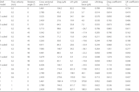
Results from the CFD simulations at 0.2, 0.6 and 1 m/s flow velocity are found in (Table2).
Drag and lift at 0° orientation
In their original size and at flow velocity of 0.2 m/s as well as 0° orientation, drag and lift forces decreased, as expected, from shell 1 to shell 3 (Fig. 4a, b). When scaled to the height of shell 1, drag (104.2 μN) and lift (82.2 μN) forces on shell 1 were approximately twice as high as on shells 2 and 3, which experienced similar drag (59.8 and 64.5μN, respectively) and lift forces (34.1 and 35.8 μN, respectively) (Fig.4a, b). The lift coefficient CL
showed a similar pattern, with the highest value for shell 1 (0.754) and identical values for the scaled shells 2 and 3 (0.485). Although the highest drag coefficient CD was
also found for shell 1 (0.956), the difference to the scaled shell 2 (0.850) and shell 3 (0.873) was not so pro-nounced. Drag forces were on average 1.7 times higher than lift forces (mean drag-on-lift ratio = 1.731 ± 0.269) and 8.6 time higher than lateral forces (8.551 ± 1.278). Drag (Kendall’s Tau = 0.801, P = 0.0026), lift (Kendall’s Tau= 0.738,P= 0.0056), and the lift-on-drag ratio (Ken-dall’s Tau = 0.609, P = 0.0221) on shells 1–3 increased
with increasing flow rate, but never did lift forces sur-pass drag forces.
Drag and lift with rotation
The rag forces increased with increasing rotation angle of the shells against the flow (Pearsonr= 0.671,P= 0.0062; drag0°= 62.23 ± 25.84, drag45°= 71.38 ± 20.72, drag90°=
117.24 ± 30.50 μN) (Fig. 4a), obviously because the cross-sectional areas of the objects increased with rotation angle (r = 0.625, P = 0.0137). Unlike drag, lift forces de-creased with increasing rotation (Kendall’sTau=−0.552, P= 0.0041; lift0°= 39.07 ± 25.08, lift45°= 25.66 ± 11.13, lift 90°= 11.72 ± 15.37μN) (Fig.4b). The lift-on-drag ratio
de-creased significantly with increasing rotation angle of the shell towards the flow (Kendall’s Tau =−0.665, P = 0.0005), but was not affected by shell height (Kendall’s Tau = 0.210, P = 0.4527), the cross-sectional area of the shell (Pearsonr=−0.212,P= 0.4487), nor by shell shape (Kendall’sTau=−0.299,P= 0.1202).
Lateral force
As expected from dextral-coiling shells aligned with the flow direction, the shells experienced a slight horizontal shifting force, perpendicular to the flow direction, directed to the left (7.23 ± 2.54 μN) (Fig. 4d). When rotated
Table 2Results from the computational fluid dynamics simulations
Shell model
Flow velocity (m/s)
Rotation angle (°)
Cross sectional area (mm2)
Drag (μN) Lift (μN) Lateral force (μN)
Lift/drag Drag coefficient CD
Lift coefficient CL
1 0.2 0 5.461 104.2 82.2 10.6 0.789 0.956 0.754
2 0.2 0 2.780 45.2 23.3 5.7 0.514 0.814 0.419
2 scaled 0.2 0 3.525 59.8 34.1 8.4 0.570 0.850 0.485
3 0.2 0 2.459 37.6 19.9 4.0 0.530 0.765 0.406
3 scaled 0.2 0 3.701 64.5 35.8 7.3 0.555 0.873 0.485
1 0.2 45 5.713 98.6 69.7 −26.7 0.706 0.865 0.611
2 0.2 45 3.342 52.7 10.8 −17.4 0.205 0.790 0.162
2 scaled 0.2 45 4.236 71.2 15.0 −24.0 0.211 0.842 0.178
3 0.2 45 3.263 50.0 12.2 −19.6 0.244 0.768 0.188
3 scaled 0.2 45 4.911 84.3 20.6 −33.4 0.244 0.860 0.210
1 0.2 90 7.083 148.7 39.2 −36.1 0.264 1.051 0.277
2 0.2 90 4.481 88.5 4.4 −22.2 0.050 0.990 0.050
2 scaled 0.2 90 5.679 121.8 5.9 −31.6 0.048 1.074 0.052
3 0.2 90 4.321 83.1 4.2 −19.4 0.050 0.963 0.048
3 scaled 0.2 90 6.504 144.1 4.9 −33.5 0.034 1.110 0.038
1 0.6 0 5.461 714.4 651.3 119.8 0.912 0.728 0.664
2 0.6 0 2.780 296.1 198.1 40.1 0.669 0.593 0.396
3 0.6 0 2.459 270.6 193.0 19.4 0.713 0.612 0.437
1 1 0 5.461 1861.4 1772.9 370.8 0.952 0.683 0.650
2 1 0 2.780 744.3 611.7 193.1 0.822 0.536 0.441
anticlockwise, the lateral force had a higher intensity and was oriented in the opposite direction (Kendall’stau =− 0.665,P = 0.0006), quasi pushing the shells back into the optimal alignment with the flow. There was no significant difference in intensity between 45° (−24.22 ± 6.26μN) and
90° (−28.54 ± 7.35μN) (t= 0.999,P= 0.3467) (Fig.4d). At 0° orientation, shell 1 experienced the highest lateral force (8.6 μN), scaled shells 2 (8.43 μN) and 3 a similar force (7.34 μN) (Fig. 4d). The lateral forces increased with in-creasing flow velocity (Kendall’sTau= 0.866,P= 0.0012).
a
b
c
d
Fig. 4Drag forces (a), lift forces (b), lift-on-drag ratio(c) and lateral forces (d) exerted on the shell models at 0.2 m/s flow rate at the different rotation angles in the computational fluid dynamics simulations. Triangle = shell 1; square = shell 2; inversed triangle = shell 3; black = models scaled to same height as shell 1; grey = original size. Overlapping symbols were slightly displaced along the x axis to increase their visualization
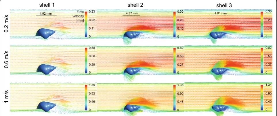
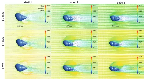
Laminar to vortical flow transition
A transition from laminar to vortical flow was observed for all three shell models at all tested flow velocities (Figs. 5 and 6). A flow separation in layers of different flow velocities was present on the upper side of the shells; the closer to the shell, the lower was the flow rate of a layer. The starting point of the flow separation was located far more anterior on the upper shell side and the flow deceleration was strongest at the ventral side of the shells, where the flow perturbations were located (Fig.5). The widths of the zones including vortices were propor-tional to the widths of the shells (Fig.6).
Flow tank experiment
Shell height varied between 2.19 and 4.41 mm (3.47 ± 0.52 mm – mean ± sd) across all specimens, shell width between 1.40 and 2.53 mm (1.90 ± 0.30 mm). Shell height and shell shape did not differ significantly between lake and spring brook sites (theight= 0.8902,P= 0.3730;tshape=
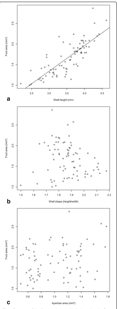
1.7338,P = 0.0870). The aperture area was positively cor-related with shell height (Kendall’sTau= 0.192,P= 0.012) and shell width (Tau= 0.184,P= 0.016), but not with shell shape (Tau=−0.011,P= 0.885). The maximum foot size was only correlated with shell height (Fig. 7a), but not with shell shape (Fig. 7b), the interaction of shell height and shape, aperture area (Fig.7c), habitat type, population origin or the interaction of aperture surface and popula-tion origin (Table 3). Thus, our hypothesis that foot size
could be predicted by shell shape or aperture size was rejected. Both, the aperture and foot areas corrected for shell height did not vary between our lake and spring sites (t relative aperture = 0.0003, P = 0.9998;t rela-tive foot =−1.1115, P = 0.2698). The mean detachment
speed was 0.739 ± 0.135 m/s and ranged from 0.46 to 0.96 m/s. Finally, the LM with detachment speed as response variable did not retain any of the explana-tory variables, i.e. detachment was not determined by shell height or shape, foot size, aperture area, habitat or population origin.
Discussion
Freshwater gastropods commonly show larger and more globular shell shapes with a larger aperture area in lotic vs lentic habitats. Here, we used the generalist snail P. antipodarum to investigate the potential hydrodynamic advantages of these counterintuitive high-flow shell morphologies using CFD simulations and a flow tank experiment. We hypothesized that these shell morpholo-gies reduce the dislodgement risk by allowing a larger foot for increased attachment strength and by reducing the ratio of lift vs drag forces acting on the shells.
Higher drag and lift forces on larger and wider shells As expected, the drag forces measured in our CFD simu-lations increased with the size of the shells, and were highest for the most globular shell, although of similar
magnitude for the intermediate and slender shell morphs when scaled to the same height. The drag was also always the highest force experienced by the shells com-pared to the lift or lateral forces. Our hypothesis that the presence of wider shells with shorter spires in lotic envi-ronments could be explained by an adaptation against lift rather than drag forces was rejected. The lift-on-drag ratio was even the highest for the most globular shell. Globular shells also produced a wide vortical zone underneath the shell.
The starting point of the flow separation was located far more anterior on the upper shell side, unlike starting from the tip as detected by Statzner & Holm [4] by Laser Doppler Anemometry. The flow deceleration was strongest at the ventral side of the shells, where the flow perturbations were located, which matched with the dead water zones, i.e. a zone where the flow velocity fluctuates around 0 m/s, found by Statzner & Holm [4]. It is important to note that in the CFD simulations, the forces on the shells alone were tested without the presence of the snail body carrying the shell. This certainly affected the flow conditions at the boundary layer at the bottom and the lift forces acting on the shells as the presence of a head and foot under the shell would prevent water passing underneath it, thus increasing upwards directed lift forces resulting from the acceleration of the flow along the upper shell sur-face alone. Similarly, the vortices that were observed under the ventral side of the shells would probably be reduced. In future experiments, it would therefore be interesting to simulate the flow around shells includ-ing the snail bodies; however, it will not be straight-forward to account for the soft and adaptive body consistency.
Drag and lateral forces explain rheotaxis
P. antipodarum is known to show rheotactic behavior, i.e. to align its body with the direction of a current ([52], personal observations). As drag and lateral forces increase with increasing rotation of the snail out of the flow, rheotaxis could be a way to decrease the dislodge-ment risk through those forces. In contrast, lift de-creased with increasing rotation, possibly mitigating the effects of drag and lateral forces.
a
b
c
Fig. 7Foot area of theP. antipodarumindividuals used in the flow tank experiment plotted against shell height (a), shell shape (b) and aperture area (c)
Table 3Parameter estimates of the optimal linear model for the foot area in the flow tank experiment. SE = standard error
Estimate SE t P
Intercept −1.310 0.154 8.490 < 0.0001
Shell height 2.46 × 10⁻⁴ 1.87 × 10⁻⁵ −13.173 < 0.0001
Shell shape −0.106 0.076 1.383 0.1710
Residual standard error = 0.0859, df = 76, multiple R2
Foot size and dislodgement speed uncorrelated to shell shape
In the flow tank experiment, the foot size was only pre-dicted by the size of the shell, not shell shape or aperture size. Although empirical evidence is scarce, researchers have long used the aperture area of gastropods as a proxy for the foot area (e.g. [14]). Unlike the soft body it is indeed easier and more convenient to measure the hard, external shells in gastropods, which can be done on fixed specimens or empty shells. Our findings show that this assumed aperture/foot area correlation should be used with caution and cannot be generalized for all aquatic gastropod species.
The dislodgement speed varied between 0.46 and 0.96 m/s, which is within the flow velocity range experienced by this snail in the field [22, 23]. The minimum dis-lodgement speed was twice as high as the highest flow rate 4.5–5 mm longP. antipodarumcould stay attached in preliminary trials by Levri & Clark [50]. The range of dislodgement speeds was similar to the 0.33–0.86 m/s range measured in flow tank experiments for various other freshwater gastropods except limpet-shaped spe-cies, which could resist currents that were almost three times as high (e.g. [16–18,53]).
The dislodgement speed could not be explained by shell, aperture and foot size, nor by shell shape or the habitat type and population the snails were originally collected from. If not by shell morphology or foot size, aquatic gastropods likely present other adaptive traits to reduce the dislodgement risk by flow, for instance through behaviour or increasing the stickiness of the pedal mucus. For example, variation in rheotaxis and dispersal was demonstrated between same sizedP. anti-podarum from different invasive clones [52]. Pedal mucus plays an important role for the adhesion of gas-tropods due to its viscoelasticity (reviewed by [54, 55]). Some aquatic gastropods are known to change the adhe-sion tenacity of their pedal mucus through changing its composition when alternating between active mobile and glued static states (e.g. inLittoraria irrorata [56] or Lottia limatula [57]). During fieldwork in New Zealand we encountered two river populations of P. antipo-darum, which apparently had a stickier mucus and crawled on the exposed faces of stones in contrast to their conspecifics in other localities. Thus, there exists a potential for aquatic gastropods to counter the variations in flow and decreasing dislodgement risks by varying these traits.
Conclusions
The integration of our multi-disciplinary approaches pro-vided further insights into the adaptations of shells to flow. Otherwise, our conclusions would have remained ambiguous or even different. Our hypothesis that the
controversial presence of globular shelled gastropods in lotic environments could be explained by an adaptation against lift rather than drag forces was rejected. Both, drag and lift forces were stronger on globular compared to slender shells. This explains why slender shells showed higher fitness, measured as the number of brooded em-bryos, compared to globular ones in high flow environ-ments in both native and invasive populations [22,23]. An absolutely or relatively larger foot size did not explain the presence of more globular shells in lotic environments, ei-ther. Foot size inP. antipodarum was only predicted by the size of the shell, not by shell shape or aperture size, showing that the assumed aperture/foot area correlation should be used with caution and cannot be generalized for all aquatic gastropod species. Finally, shell morphology and foot size were not related to dislodgement speed in our flow tank experiment. Hence, other traits must play a major role in decreasing the dislodgement risk in stream gastropods, e.g. specific behaviours or pedal mucus sticki-ness. Although we did not find that globular shells are ad-aptations for reducing the dislodgement risk, we cannot rule out that they are still flow related adaptations. For in-stance, globular shells are more crush-resistant and there-fore perhaps adaptive in terms of diminishing damage caused by tumbling after dislodgement as suggested by [11]. Globular shells of gastropods are also known to be an adaptation against crush-type predators (e.g. [58, 59]). Therefore, the increase in globularity of the shells in lotic habitats represents maybe an adaptation against habitat specific predators as recently demonstrated for Lithasia geniculata [12]. We conclude that in aquatic gastropods the relationships of shell morphology and habitat are more complex than assumed. Flow velocity certainly does not exert the only selective pressure as already suggested by our foregoing field studies [22,23].
Additional file
Additional file 1:Table S1.Reynolds numbers (Re) for the flow in the channel and for the shell models at 0° rotation from the flow direction in the computational fluid dynamic simulations. (DOCX 12 kb)
Acknowledgements
Jakob Krieger is acknowledged for running theμCT and introducing one of us (GV) to the AMIRA software. We thank Silke Fregin for her assistance with snail maintenance and the flow tank experiment, and Michael Schmitt for operating the high-speed camera. We are grateful to Helmut Schulz and his colleagues of the mechanical workshop of the University of Greifswald for constructing the flow tank according to our design. Three anonymous reviewers are thanked for their constructive and valuable comments.
Funding
This study was part of the Research Training Group 2010 RESPONSE funded by the Deutsche Forschungsgemeinschaft (DFG).
Availability of data and materials
Authors’contributions
Study design: MH, GV, GK. Data analysis: GV, MH. Computational fluid dynamics simulations: GV, MB, HH. Flow tank experiment: KK, MH. Manuscript: GV, MH, HH, MB, GK, KK. All authors gave their final approval for publication.
Ethics approval and consent to participate
Ethical approval and consent to participate were not required for this work.
Consent for publication Not applicable.
Competing interests
The authors declare that they have no competing interests.
Publisher’s Note
Springer Nature remains neutral with regard to jurisdictional claims in published maps and institutional affiliations.
Author details
1Vogelwarte, Zoologisches Institut und Museum, Universität Greifswald,
Soldmannstraße 23, 17489 Greifswald, Germany.2Institut für Zoologie, Rheinische Friedrich-Wilhelms-Universität Bonn, Meckenheimer Allee 169, 53115 Bonn, Germany.3Angewandte Zoologie und Naturschutz, Zoologisches Institut und Museum, Universität Greifswald, Loitzer Str. 26, 17489 Greifswald, Germany.4Lehrstuhl Strömungsmechanik, Universität Rostock, Albert-Einstein-Str. 2, 18051 Rostock, Germany.
Received: 19 April 2018 Accepted: 26 December 2018
References
1. Statzner B. How views about flow adaptations of benthic stream invertebrates changed over the last century. Int Rev Hydrobiol. 2008;93:593–605. 2. Lampert K. Das Leben der Binnengewässer. Leipzig: Tauchnik; 1899. 3. Hüber LV. Zur Naturgeschichte der Unionen. Jahrbucher des
naturhistorischen Landes-Museum von Kärnthen. 1870;10:150–7. 4. Statzner B, Holm TF. Morphological adaptation of shape to flow:
microcurrents around lotic macroinvertebrates with known Reynolds numbers at quasi-natural flow conditions. Oecologia. 1989;78:145–57. 5. Statzner B. Ökologische Bedeutung der sohlennahen
Strömungsgeschwindigkeit für benthische Wirbellose in Fließgewässern; 1987. 6. Holomuzki JR, Biggs BJF. Distributional responses to flow disturbance by a
stream-dwelling snail. Oikos. 1999;87:36–47.
7. Gore JA. Considerations of size related flow preferences among macroinvertebrates used in stream flow studies. Dev Ecol environ Qual. Balaban Press Jerusalem. 1983;2:389–98.
8. Weissenberger J, Emanns HSA, Schwoerbelt J. Measurement of lift and drag forces in the mN range experienced by benthic arthropods at flow velocities below 1.2 m s−1. Freshw Biol. 1991;25:21–31.
9. Rao MB, Rao KS. Inter and intra-specific variation of the shell of two species of the tropical freshwater snailBellamya(Mollusca: Prosobranchia). J Molluscan Stud. 1985;51:1–7.
10. Lam PKS, Calow P. Differences in the shell shape ofLymnea peregra(Müller) (Gastropoda: Pulmonata) from lotic and lentic habitats; environmental or genetic variance? J Molluscan Stud. 1988;54:197–207.
11. Minton RL, Norwood AP, Hayes DM. Quantifying phenotypic gradients in freshwater snails: a case study inLithasia(Gastropoda: Pleuroceridae). Hydrobiologia. 2008;605:173–82.
12. Minton RL, Hart KC, Fiorillo R, Brown C. Correlates of snail shell variation along a unidirectional freshwater gradient inLithasia geniculata(Haldeman, 1840) (Caenogastropoda: Pleuroceridae) from the duck river, Tennessee, USA. Folia Malacol. 2018;26:95–102.
13. Minton RL, Lewis EM, Netherland B, Hayes DM. Large differences over small distances: plasticity in the shells ofElimia potosiensis(Gastropoda: Pleuroceridae). Int J Biol. 2011;3:23–32.
14. Raffaelli DG. Recent ecological research on some European species of Littorina. J Molluscan Stud. 1982;48:342–54.
15. Kitching JA, Muntz L, Ebling FJ. The ecology of lough Ine . XV . The ecological significance of shell and body forms inNucella. J Anim Ecol. 1966;35:113–26.
16. Jobin W, Ippen A. Ecological design in irrigation canals for snail control. Science. 1964;145:1324–7.
17. Dussart GBJ. Effects of water flow on the detachment of some aquatic pulmonate gastropods. Am Malacol Bull. 1987;5:65–72.
18. Moore IJ. Effects of water currents on fresh-water snailsStagnicola palustris andPhysa propinqua. Ecology. 1964;45:558–64.
19. Haase M. The radiation of hydrobiid gastropods in New Zealand: a revision including the description of new species based on morphology and mtDNA sequence information. Syst Biodivers. 2008;6:99–159. 20. Warwick T. Strains in the molluscPotamopyrgus jenkinsi(Smith). Nature.
1952;169:551–2.
21. Winterbourn MJ. Population studies on the New Zealand freshwater gastropodPotamopyrgus antipodarum(gray). J Molluscan Stud. 1970;39: 139–49.
22. Verhaegen G, McElroy KE, Bankers L, Neiman M, Haase M. Adaptive phenotypic plasticity in a clonal invader. Ecol Evol. 2018;8:4465–83. 23. Verhaegen G, Neiman M, Haase M. Ecomorphology of a generalist
freshwater gastropod: complex relations of shell morphology, habitat and fecundity. Org Divers Evol. 2018;18:425–41.
24. Alonso Á, Castro-Díez P. The exotic aquatic mud snailPotamopyrgus antipodarum(Hydrobiidae, Mollusca): state of the art of a worldwide invasion. Aquat Sci. 2012;74:375–83.
25. Bowler PA. The rapid spread of the freshwater hydrobiid snailPotamopyrgus antipodarum(gray) in the middle Snake River, southern Idaho. Proc Desert Fishes Counc. 1991;21:173–82.
26. Collado GA. Out of New Zealand: molecular identification of the highly invasive freshwater molluskPotamopyrgus antipodarum(gray, 1843) in South America. Zool Stud. 2014;53:1–9.
27. Ponder WF.Potamopyrgus antipodarum: a molluscan colonizer of Europe and Australia. J Molluscan Stud. 1988;54:271–86.
28. Shimada K, Urabe M. Comparative ecology of the alien freshwater snail Potamopyrgus antipodarumand the indigenous snailSemisulcospiraspp. Venus. 2003;62:39–53.
29. Dybdahl MF, Lively CM. Diverse, endemic and polyphyletic clones in mixed populations of a freshwater snail (Potamopyrgus antipodarum). J Evol Biol. 1995;8:385–98.
30. Neiman M, Paczesniak D, Soper DM, Baldwin AT, Hehman G. Wide variation in ploidy level and genome size in a New Zealand freshwater snail with coexisting sexual and asexual lineages. Evolution. 2011;65:3202–16. 31. Hughes RN. Evolutionary ecology of parthenogenetic strains of the
prosobranch snail,Potamopyrgus antipodarum(gray)= P. jenkinsi (Smith). Malacol Rev. 1996;28:101–14.
32. Jacobsen R, Forbes VE, Skovgaard O. Genetic population structure of the prosobranch snailPotamopyrgus antipodarum(gray) in Denmark using PCR-RAPD fingerprints. Proc Biol Sci. 1996;263:1065–70.
33. Gangloff MM. The New Zealand mud snail in Western North America. Aquat Nuis Species. 1998;2:25–30.
34. Hauser L, Carvalho GR, Hughes RN, Carter RE. Clonal structure of the introduced freshwater snailPotamopyrgus antipodarum(Prosobranchia: Hydrobiidae), as revealed by DNA fingerprintring. Proc Biol Sci. 1992;249:19–25. 35. Vergara D, Fuentes JA, Stoy KS, Lively CM. Evaluating shell variation across
different populations of a freshwater snail. Molluscan Res. 2016;5818:1–13. 36. Haase M. Clinal variation in shell morphology of the freshwater gastropod Potamopyrgus antipodarumalong two hill-country streams in New Zealand. J R Soc New Zeal. 2003;33:549–60.
37. Kistner EJ, Dybdahl MF. Parallel variation among populations in the shell morphology between sympatric native and invasive aquatic snails. Biol Invasions. 2014;16:2615–26.
38. Holomuzki JR, Biggs BJF. Habitat-specific variation and performance trade-offs in shell armature of New Zealand mudsnails. Ecol Soc Am. 2006;87:1038–47.
39. Losos JB, Miles DB. Adaptation, constraint, and the comparative method: phylogenetic issues and methods. In: Ecol Morphol Integr Org Biol: University of Chicago Press; 1994. p. 60–98.
40. Kingsolver JG, Pfennig DW. Patterns and power of phenotypic selection in nature. Bioscience. 2007;57:561–72.
41. Rieseberg LH, Widmer A, Arntz AM, Burke JM. Directional selection is the primary cause of phenotypic diversification. Proc Natl Acad Sci. 2002;99:12242–5.
43. Stokes GG. On the theories of the internal friction of fluids in motion, and of the equilibrium and motion of elastic solids. Trans Cambridge Philos Soc, vol. 8: University Press; 1880.
44. Anderson JD, Wendt J. Computational fluid dynamics: Springer; 1995. 45. Chung TJ. Computational fluid dynamics: Cambridge University Press; 2010. 46. Ferziger JH, Peric M. Computational methods for fluid dynamics: Springer
Science & Business Media; 2012.
47. Reddy JN, Gartling DK. The finite element method in heat transfer and fluid dynamics: CRC press; 2010.
48. Hammer Ø, Harper DAT, Ryan PD. PAST - PAlaeontological STatistics. Paleontol Electron. 2001:1–9.
49. Team RC. R: a language and environment for statistical computing. Vienna: R Foundation for Statistical Computing; 2013.
50. Bates D, Mächler M, Bolker B, Walker S. Fitting linear mixed-effects models usinglme4. J Stat Softw. 2015;67:1–48.
51. Chambers JM. Linear models, eds. In: JM Chambers TJ Hast Wadsworth Brooks/Cole; 1992.
52. Levri EP, Clark TJ. Behavior in invasive New Zealand mud snails
(Potamopyrgus antipodarum) is related to source population. Biol Invasions. 2014;17:497–506.
53. Dorier A, Vaillant F. Observations et experiences relatives a la resistance au courant de divers invertebres aquatiques. Trav Lab Hydrobiol Pisic Univ Grenoble. 1954;45:9–31.
54. Davies MS, Hawkins SJ. Mucus from marine Molluscs. Adv Mar Biol. 1998;34:1–71.
55. Smith AM. Gastropod secretory glands and adhesive gels. In: Biol Adhes Syst: Springer; 2010. p. 41–51.
56. Smith AM, Morin MC. Biochemical differences between trail mucus and adhesive mucus from marsh periwinkle snails. Biol Bull. 2002;203:338–46. 57. Smith AM, Quick TJ, St. Peter RL. Differences in the composition of adhesive
and non-adhesive mucus from the limpetLottia limatula. Biol Bull Marine Biological Laboratory. 1999;196:34–44.
58. DeWitt TJ, Robinson BW, Wilson DS. Functional diversity among predators of a freshwater snail imposes an adaptive trade-off for shell morphology. Evol Ecol Res. 2000;2:129–48.