IJEDR1702220
International Journal of Engineering Development and Research (www.ijedr.org)1412
Hand talk
1
Sachin Kumar Verma,
2Rishabh Kesarwani,
3Mrs. Rasveen
1UG Student,
2UG Student,
3Assistant Professor
1Department of Electronics and Communication Engineering
1Dronacharya Group of Institutions,Greater Noida,India
Abstract - Communication thr ough talking is a natur al way of life. Howe ver, due to various causes some persons are not able to communicate in this manner e .g. de af and dumb persons. These differently able d persons nee d assistance to fulfill their daily routi ne task. Today’s technol ogy can be effecti vely utilized to come to their rescue. Most often differentl y able d persons are not treate d as the part of the society. To pr ovi de the m an oppor tunity to be like a nor mal person, we have de velope d a hand gesture base d pr ototype name d “ HANDTALK”.
Index Terms- Hand gesture recogni tion, Flex Sensor, Ar duino, and GS M
I. INTRODUCTION
Gestures are natural and intuitive forms of interaction and commun ication used to convey messages using hand shapes, hand
move ments and orientations. Technology has always been of great help to the disabled and given them a help ing hand to allow them to live a normal and healthy life like others. We have come up with a novel idea of a g love named HANDTA LK that will convert the hand move ments (gestures) into a corresponding message and allow the indiv idual to e xpress themselves better.
A sensor equipped glove needs to be worn on the hand. The heart of the system i.e. Fle x Sensors fixed on a hand glove pic k up signals generated by the gesture made by the individual and with the help of Arduino the analog inputs are converted into d igital for various gestures and for every particula r gesture there is specific output which is converted in to a specific message. W hen the person perform a particular gesture, the predefined message for that gesture is displayed on the LCD a long with a beep (sound) and that specific messa ge is also transmitted in the form of te xt or ca ll with the help of GSM module to the various registered numbers.
Handtalk converts a hand gesture made by the wearer to the corresponding message. Sensors in the glove pick up gestures and transmit the data wire lessly to the mobile phone via SMS/Ca ll with the help of GSM module and to the LCD display with the help of Ardu ino. The glove is completely independent of the LCD display section i.e. the receiver section can be placed anywhere according to the requirement either on doctor‟s chamber or in the one‟s who is concerned with that person. That means the person just needs to wear a weightless glove and is having to perform e ffort less gestures to express his needs all his needs on finger tips. Moreover, he can also control the basic home appliances like AC‟s , Light etc., all by just performing few predefined gestures. Exa mp le,If the patie nt performs a gesture of fist (most often we people form the fist in case of fear, pain, stroke, e mergency, etc.) there would be a messag e displayed on the LCD“CRITICA L SITUATION” or “EMERGENCY” along with a beep and the particular message will also be sen t to the doctor‟s phone or to the relative‟s. Another example is, if the wearer performs a gesture of “V” (victory symbol, predefined), then the lights will be ON, and by performing the same gesture again the light will be OFF. Similarly, we can do the same in the case of AC, Fan or any other devices.
In addition to this in HANDTA LK pulse sensor is added to monitor the heartbeats of the person and displaying it on the LCD, so that the doctor can continuously monitor the heart rate easily and as per requirements different more sensors can be configured to judge the various parameters of the body. No w in case, the heartbeat is getting too low or too high, the doctor will get the ale rt too by a SMS and call.
II. LITERATURE REVIEW
IJEDR1702220
International Journal of Engineering Development and Research (www.ijedr.org)1413
computer then reads the numerica l values and converts them into the letters which appear on the screen. The ma in disa dvantage with this model was that a computer or a laptop was always required for its functioning which made it less portable[4].
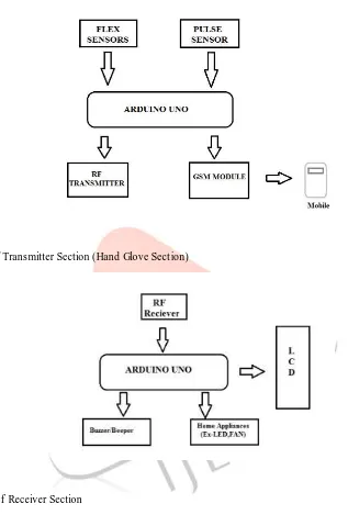
III. B LOCK DIAGRAM OF PROPOS ED S YSTEM:
Fig 1: Bloc k diagra m of Transmitter Section (Hand Glove Sect ion)
Fig 2: Block Diagra m of Receiver Section
IV. REVIEW OF S YS TEM COMPONENTS
Arduino Nano
IJEDR1702220
International Journal of Engineering Development and Research (www.ijedr.org)1414
Microcontroller Atmega 328pThe ATMEGA 328p is 8-bit A VR RISC-based microcontroller co mbines 32KB ISP flash me mory with read -while-write capabilities, 1024B EEPROM, 2KB SRAM, 23 general purpose I/O lines, 32 general purpose working registers, three fle xible t imer/counters with compare modes, internal and external interrupts, serial programmable USART, a byte -oriented 2-wire serial interface, SPI serial port, a 6-channel 10-bit A/D converter, progra mmab le watchdog time r with internal oscillator, and five software selectable powe r saving modes. The device operates between 1.8-5.5 volts. It is developed by Atme l. In this system this microcontroller is used in receiver parts for controlling the LCD, Buzze r, LCD and Motor.
Flex sensor
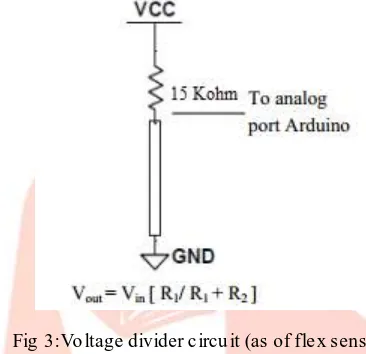
Fle x sensors are resistive carbon elements. When bent, the sensor produces a resistance output correlated to the bend radius [9].The variation in resistance is approximately 10 to30 K Oh m„s. An unflexed sensor has 10Koh m resistance and when bent the resis tance increases to 30Koh m at 90o [3].The sensor is about ¼ inch wide, 4-1/2 inches long[].
Fig 3:Vo ltage divider c ircu it (as of fle x sensor)
The sensor is incorporated in device using a voltage divider network. Vo ltage divider is used to determine the output
voltage across two resistances connected in series i.e. basically resistance to voltage converter. The resistor and fle x forms a voltage divider which div ides the input voltage by a ratio determined by the variable and fixed resistors.
RF Module (Receiver and Transmitter)
The RF module, as the name suggests, operates at Radio Frequency. The corresponding frequency range varies between 30 kHz & 3 00 GHz. In this RF system, the digital data is represented as variations in the amplitude of carrier wave. This kind of modulation is known as Amplitude Shift Keying (ASK). This RF module co mprises of an RF Transmitter and an RF Receiver. The transmitter/receiver (Tx/ Rx) pa ir operates at a frequency of 434 M Hz. An RF transmitter receives serial data and transmits it wire lessly through RF through its antenna connected at pin4. The transmission occurs at the rate of 1Kbps - 10Kbps.The transmitted data is received by an RF receiver operating at the same frequency as that of the transmitter. RF module can be easily interfaced by Arduino and other microcontrollers.
GSM/GPR S Module
GSM/ GPRS module is used to establish commun ication between a computer and a GSM-GPRS system. Global System for Mobile communicat ion (GSM ) is an architecture used for mobile co mmunicat ion in most of the countries. Global Pac ket Rad io Service (GPRS) is an e xtension of GSM that enables higher data transmission rate. GSM/ GPRS module consists of a GSM/ GPRS modem assembled together with power supply circuit and communication interfaces (like RS-232, USB, etc.) for computer. GSM mo dule uses the AT Co mmands for performing diffe rent task like Sending SMS, Call, and Data Connections etc. In this system we h ave used sim900A GSM Module which is interfaced with Arduino Nano.
Pulse Sensor
IJEDR1702220
International Journal of Engineering Development and Research (www.ijedr.org)1415
fingertip and plug it into your 3 or 5 Vo lt Arduino and you‟re ready to read heart rate! The 24" cable on the Pulse Sensor is terminated with standard male headers so there‟s no soldering required. Of course Arduino examp le code is available as well as a Processing sketch for visualizing heart rate data.
V. WORKING PRINCIPLE OF THE S YS TEM Working of Transmitter section
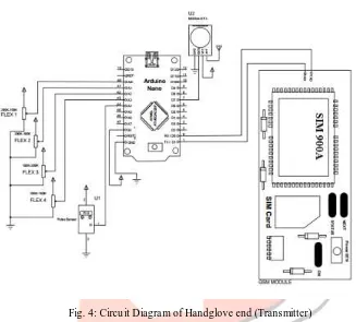
Fig. 4: Circu it Diagra m of Handglove end (Transmitter)
In this Schematic Four PIR sensors named as P1, P2, P3, and P4 to the analog pins A0, A1, A 2, and A3 a re connected with Arduino Uno. The generated code for the sensor output is given to the RF transmitter module for transmission to the receiver via TX p in of Arduino Uno (Digital Pin 1).LED is connected with pin no. 13 of the Arduino. A +5v regulated supply is used as power supply for Arduino Uno, RF module and sensors.
This section is the primary part of the system. It consists of hand glove (Fle x sensors and Heartbeat module), GSM mo dule, RF Transmitter and Arduino UNO as a Controlle r. All the gestures made by the hand glove (with Fle x sensor) are converted into diffe rent messages and commands for the operation of diffe rent devices. For e xa mple , if we want to start a fan, a co mmand is sent to th e receiver end by the microcontroller with the help of RF module to the receiver end and the fan is easily controlled by the corresponding gest ures. Another e xa mple is if we need water then ma ke the corresponding gesture with hand glove and this gesture is converted into t ext message and sent to the other person through the GSM module. Now using the Android app we can convert the text messages into voice also.
IJEDR1702220
International Journal of Engineering Development and Research (www.ijedr.org)1416
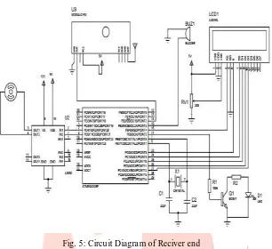
Working of the Receiver SectionFig. 5: Circu it Diagra m of Reciver end
In this section, Microcontroller ATM EGA 328P is used with RF Receiver, Bu zzer, Motor Driver Module and LCD. The buzze r is connected via transistor BC547 to Microcontroller. Motor driver is interfaced with Pin no 8 and 9 of the microcontrolle r. The targeting control system by LED wh ich is connected on digital pin 13 of the microcontrolle r and Alarming System is connected with pin no. 12.Wholw circuit is operated with 5V power supply .This section is mainly for the output, the massages which is sent by the GS M Module and Eme rgency alerts are shown in the LCD with a short beep by buzzer. LCD and Motor can be controlled by makin g gestu re through glove, these sections shows how we can control any devices wirelessly by ma king gestures.
IJEDR1702220
International Journal of Engineering Development and Research (www.ijedr.org)1417
Fig. 6: Hand glove (Transmitter End) of proposed system
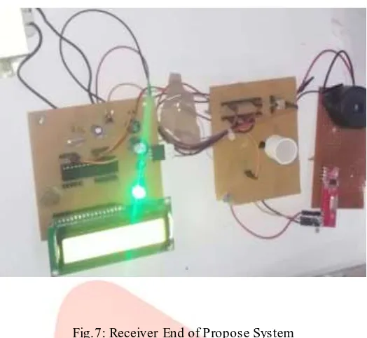
Fig.7: Receiver End of Propose System
Figure 6 and 7 shows the hardware system of the project. Figure 6 is of Hand Glove with Fle x Sensor, GSM Module, Arduino Nano and RF Module acting as Transmitter end. Fig. 7 is receiver end which is controlled by At mega 328p microcontrolle r, this part is only for displaying the output and performing the actions like light on ,fan on or for a lert.
The evaluation of HANDTA LK was carried out for 6 Massag es (i.e. - Water Required by Patient, Food Required by Patient, Eme rgency Situation etc.) Sentences are preloaded by program; the output is depending upon the gestures and combination of gestures. Exa mple the analog value of the sensors are 255,230,215,220 ,then the output as a text will be “Food required by Patient” and same massage will be sent to family me mbe rs also. Similarly, other massages are depends upon combinations of analog values of the fle x sensors. Table 1 shows the Output voltage across a voltage divider network with constant resistance of 22Kohms, the digital value and the corresponding resistance for different bending angles of flex 2.5” mounted in thumb and pinky fingers.
TABLE 1: RESISTA NCE AND CORRELATEDBENDING – FLEX 2.5”
DEGREE VOLTAGE
(ANALOG)
DIGITAL RES ISTANCE
(OHMS )
0 4.001 255 30020 15 4.100 240 31001 30 4.315 230 36010 45 4.400 225 40562 60 4.750 215 48552 75 4.950 200 56000 90 5.100 190 62500
IJEDR1702220
International Journal of Engineering Development and Research (www.ijedr.org)1418
Fig 8: V-R characteristics Fig 9: Plot of degree vs. resistance of fle x 2.5”
Figure belo w shows the output results of different gestures.
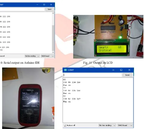
Fig. 10: Se ria l output on Arduino IDE Fig. 11 :Output on LCD
IJEDR1702220
International Journal of Engineering Development and Research (www.ijedr.org)1419
As per the figure 10,11 the gloves in the normal condition shows the value of (220,201,223,25 5), as soon as the operator performs a particular gesture the values changes to (213,64,229,255) that corresponds to the messag e “CRITICAL” and the same message will also get transmitted in the form o f te xt or call v ia GSM module as show in figure 12.
Similarly, for a ll other gestures we can opt for te xt or ca ll as per the require ments.
As per figure 13, when the values of the fle x sensors are nearly (238, 56,225,216) the resultant message would be “FAN ON”
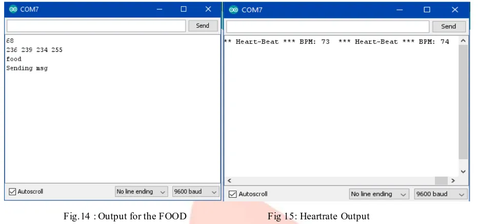
Fig.14 : Output for the FOOD Fig 15: Heartrate Output
As per Fig.14, when the values changes to (236,239,234,255) the message displayed would be “FOOD” and also the same message will be transmitted in the form of te xt or ca ll.
Fig. 15 is showing the Heart rate of the patient and continues to change and display as per the patient‟s Heart Beat. When Heart beat is above or normal condition then system will send alert message also to the relative‟s mobile nu mbers.
VII. CONCLUS ION
The project proposes a translational device fo r deaf-mute people using glove technology. The proposed technique has enabled the place ment of four fle x sensor, heartbeat sensor and GSM Module on to a glove. The RF Module and GSM Module is provide wireles s connectivity to system and it helps to control the other system. Further the device will be an apt tool for deaf mute community to learn gesture and words easily. The project can be enhanced to include accelerometer„s to capture the orientation of hand move ments once the gesture is made. Th is will e xpand the capability to translate larger gesture.
VIII. ACKNOWLEDGMENT
We are heartily thankful to our Department of Electronics and Commun ication Engineering, H.O.D. Mr. Vinod Kumar, Assistant Pr of. Mr. Ra j Ranjan Prasad (Dept. of ECE), Assistant Prof. Mr. Nit in Ku mar (Dept. of ECE), Ms. Gunjeet Kaur (Ex- Assistant prof. Dept. of ECE) and all the faculty me mbers of the department whose encouragement, guidance and support from the in itia l to the final level enabled us to develop an understanding of the project.
Lastly, we offe r our regards to all those who supported us during the comp letion.
REFRENCES
[1] T. Baudel, M. Baudouin-Lafon, Charade: re motecontrol of objects using free-hand gestures, Co mm. A CM 36 (7) (1993) 28– 35.
IJEDR1702220
International Journal of Engineering Development and Research (www.ijedr.org)1420
[5]G. R. Karlan, “Manual communicat ion with those who can hear,” in Manual Co mmunication: Implications for Education, H. Bornstein, Ed., pp. 151–185, Gallaudet University Press, Washington, DC, USA,1990.
[6] Stokoe, Willia m C. "Dict ionary of American Sign Language on Linguistic Princ iples", Linstok Press. ISBN 0-932130 011,1976.
[7] Nin ja P Oess, Johann Wanek and Armin Curt, "Design and evaluation of a low-cost instrumented glove for hand function assessment", Journal of Neuro Engineering and Rehabilitation 2012, 9:2.
[8]Sa ini, G.K. and Kaur, R. (2015) “ Designing real-time virtual instrumentation system for differently abled using Lab VIEW”, Int. J. Bio medical Eng ineering and Technology, Vo l. 18, No. 1, pp.86–101.