299 | P a g e
FINITE ELEMENT ANALYSIS OF TIE-ROD FOR
SPACECRAFTS
Kiran S Sankanagoudar
1, Dr.H.K.Amarnath
2, Prashant D. Bagalkot
3,
Mukund Thakur
41
M.Tech Student, Gogte Institute of Technology, Belgaum, (India)
2
Professor, Gogte Institute of Technology, Belgaum, (India)
3
Scientist/Engineer-SE, ISRO Satellite Centre, Bangalore, (India)
4
Scientist/Engineer-SC, ISRO Satellite Centre, Bangalore, (India)
ABSTRACT
This paper describes the design and mechanism for the deployment of Equipment panel of a spacecraft. For this
a tie rod is designed and analysis is done in UG NX 7.5, the design analysis section provides data on linear
Buckling analysis. Both the ends of the Tie rod are hinged so that the Equipment panels assembled to Tie –rod
can be tilted from Horizontal condition to vertical condition. And safety of factor taken is 3.0.
Keywords
-
Design, Mechanisms, Linear Buckling Analysis, Tie-Rod, UG
I. INTRODUCTION
Spacecraft consists of main structure and Equipment panels which are connected through shear webs to main
structure to form a cuboid structure. Assembly, Integration and Testing (AIT) of spacecraft require number of
Mechanical Ground Support Equipment (MGSE). A Tie-Rod is designed for tilting the Equipment Panel.
1.1.
Tie-Rod
Tie-rod is selected as driving member for tilting the panel (along with panel mounting frame) from horizontal to
vertical position and vice versa. In principal, tie-rod will have central coupler with screw rods on sides, one with
left hand thread and another with right hand thread. The coupler has matching threads to accommodate these
threaded tie rods. On rotating the coupler is turned, both the rods will extend or retract based on the direction of
rotation of coupler. The ends of the rods are either eye or fork end type.
300 | P a g e
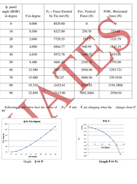
The data corresponding to panel in horizontal condition to panel in vertical condition (i.e., from 0 to 90
degrees) is presented below at an interval of 10o.
Table 1.1: Data of panel horizontal condition to vertical condition
Following graphs show how the values of , FT, and are changing when the changes from 0o to
90o
Graph
Graph
ф panel
angle (BOB')
in degree
θ in degree
F
T= Force Exerted
by Tie rod (N)
Fov, Vertical
Force (N)
FOH , Horizontal
force (N)
0
0.000
8829.00
0
0
10
0.500
8327.00
250.78
723.05
20
2.040
7729.35
552.5
1321.79
30
4.090
6964.77
940.99
1741.19
40
6.630
5972.78
1448.02
1919.61
50
9.480
4681.42
2105.76
1793.08
60
12.580
2987.72
2956.96
1293.721
70
15.880
722.67
4066.96
339.5418
80
19.310
-2425.61
5559.03
1194.3806
301 | P a g e
1.1.1 Design of Tie-Rod
Material= 30C8, Carbon Steel Yield strength= σyt = 400 N/mm2
Load acting = W= (300 x 9.81) = 2943 N and Factor of safety= 3
Assuming σyt = σyc = 400 N/mm2 Therefore, limiting stress is
The diameter of the rod is determined by considering the rod in two failure cases.
1. Compression failure
2. Buckling failure
Case-1: Considering the compression failure of the rod:
Compressive strength of the rod is given by, … (1)
Substituting the values we get the diameter of rod as
… (2)
Case-2: Considering the buckling failure of the rod:
Effective length of Tie –Rod= 2000mm
For circular cross section of diameter ‘dc’
The moment of inertia, … (3)
302 | P a g e
… (4)Radius of Gyration . . (5)
By substituting the values of radius of gyration in slenderness ratio, we get,
Slenderness ratio =
… (6)
Assuming the critical load should be more than or equal to design load,
… (7)
From Rankine Formula we have
… (8)
Where = Crushing Stress or Yield Stress in Compression = 400 N/mm2
a = Rankine Constant =
A = Cross –sectional area of Column
Substituting above values in Rankine Equation, we get
This is quadratic equation in , the solution of which gives,
Therefore,
From the above two cases it is very that the bucking of tie-rod is more pronounced than the compression failure.
303 | P a g e
Adopting the next higher standard core diameter of 26mm and pitch as 5, the nominal diameter of the Tie –rod is,and the mean diameter is,
It is assumed that the screw has single start thread; the helix angle is given by,
… (9)
Assuming Maximum possible value of coefficient of friction is 0.15 (worst case)
We have, ..(10)
The Torque (Mt) required to raise the load is given by,
.. . (11)
Now torsional shear stress is evaluated by,
… (12)
Since the induced torsional shear stress is less than the limiting stress, the design is safe.
The condition for self locking of the screw need to checked, so that the frame should not fall off due to its own weight plus the panel weight. For this case, the efficiency of the square threaded rod should be less than 50% and is calculated as follows.
… (13)
Since the efficiency of the rod is 26.8% which is less than 50%, the system is self-locking.
304 | P a g e
Now the coupler dimensions are arrived by considering the proportions being used in standard design practice.The central position of the tie rod is called coupler, the outer and inner diameter of the coupler are D and d respectively.
The inner diameter of the coupler is same as rod diameter, d = 26mm
The outer diameter of the coupler, D= 1.5d = 1.5 x 26 = 39mm
II. ANALYSIS
The FE analysis is carried out to evaluate the analytical calculations and also to validate the actual
configuration and design of the tie rod which are shown below as two separate cases.
Case-1: To validate the analytical calculations.
Case-2: Actual configuration with rods and coupler
Material Properties Description
Basically two types of materials are used for assembly – plain carbon steel and cast-iron.
Table -2 Material Properties
Material
Elastic Modulus (E) in (GPa)
Poisson’s Ratio (μ) Density (ρ) in Kg/mm3 Yield Strength (σy)in (Mpa)
Carbon Steel 30C8 207 0.29 7800 x 10-9 400
Gray
Cast-iron FG200 90 0.3 8000 x10
-9 200
2.1. Element Property Description
Table -3: Element Properties
2. 2 Boundary Conditions
Table 4: Boundary condition
Location and
description Boundary condition Loading
A Tie-rod hinged at base
Translations in X, Y & Z and rotation in X & Y
directions arrested. Rotation in Z direction is allowed. ---
B Tie-rod hinged to frame
Translations in X, Z and rotation in X, Y directions arrested. Translation in Y & Rotation in Z directions are
allowed.
Loading in Y direction
Sl. No. Region Element Type Material property
1 Rod Psolid Isotropic
Carbon steel 30C8
2 Coupler Psolid Isotropic
305 | P a g e
CASE 1. SINGLE RODIn this case a single rod of 26mm diameter and 2000mm length is taken with ends of rod as eye end..
Material of the screw rod is Carbon Steel 30C8
Finite element Model
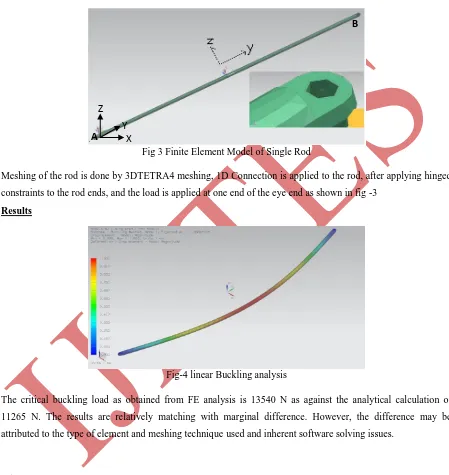
Fig 3 Finite Element Model of Single Rod
Meshing of the rod is done by 3DTETRA4 meshing, 1D Connection is applied to the rod, after applying hinged
constraints to the rod ends, and the load is applied at one end of the eye end as shown in fig -3
Results
Fig-4 linear Buckling analysis
The critical buckling load as obtained from FE analysis is 13540 N as against the analytical calculation of
11265 N. The results are relatively matching with marginal difference. However, the difference may be
attributed to the type of element and meshing technique used and inherent software solving issues.
CASE 2: TIE ROD
The tie rod consisting of rod is made of 26mm diameter and the the coupler of 39mm diameter , and the overall
length of the tie-rod is 2000mm of which the coupler and the rod has mating distance of 50mm as shown in
figure below. Other boundary conditions and loading are same as case-1.
Finite element Model
X
Z
Y
A
306 | P a g e
Finite element analysis is carried out in order to obtain the first mode Eigen value, which will when multipliedby the applied compressive load, gives the linear Buckling load.
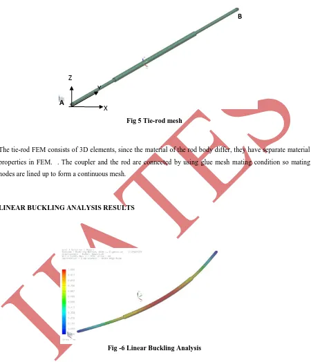
Fig 5 Tie-rod mesh
The tie-rod FEM consists of 3D elements, since the material of the rod body differ, they have separate material
properties in FEM. . The coupler and the rod are connected by using glue mesh mating condition so mating
nodes are lined up to form a continuous mesh.
LINEAR BUCKLING ANALYSIS RESULTS
Fig -6 Linear Buckling Analysis
In this case-2 the linear analysis shows the crippling load (buckling load) obtained as 20460 N. This is due to the
fact that, coupler in between the two rods adds more stiffness to the tie-rod assembly as a whole. As can be seen
from the bucking equations, critical or buckling load is directly proportional to moment of inertia (MI).
Since MI of the coupler = 91129mm4
MI of screw rod = 22431mm4
A
B
X
Z
307 | P a g e
As the MI of coupler is more than 4 times than that of the screw rod, the buckling load as obtained for thecombination of screw rod and coupler (tie-rod assembly) is reasonable and justified.
III. CONCLUSIONS
In this paper, the linear Buckling analysis method for the Tie-rods is presented.
Since, the tie-rod is the main drive element for tilting of the equipment panel. It is suggested to co-relate the
Analytical and FE results with experimental values.
Above results indicates that the induced stresses are within permissible limits and hence, the design is safe.
Acknowledgements: This study was supported by ISRO SATELLITE CENTRE. Bangalore.
REFERENCES
Journal papers:
[1] Jong-Hwi SEO, Jang-Soo CHAE and Tae-Won PARK, Solar panel Deployment Analysis of Satellite
System, JSME International journal, vol.46,pp., 2003, 507-518
[2] Young-chul Park, Seung-Kul Baek, Lightweight Design of an Outer Tie-Rod For an Electrical Vehicle,
Journal of Applied Mathematics, , Article ID : 942655, 2014.
[3] Theodore J. harkta and David f. Persons., The Design And Testing of the NEAR spacecraft Structure and
mechanisms, JOHN HOPKINS APL DIGEST, vol 19, 1998
[4] Daerae kim, and Young-Shin Lee, A study on structural safety of mechanical ground support equipment
during the launch operation of the Korea small launch vehicle (KSLV-1), journal of mechanical science
and technology, 2013, 2691-2699
[5] Msc.Ismar Alagic, FEM simulation of Tie-Rod Tensile Test. 10th international research Conference.,
2006, 769-772
Books:
[6] V. B. Bhandari, “Design of Machine Elements “2nd edition, 2006
Thesis:
[7] Anthony Delugan, Understanding the Buckling behavior of a Tie-Rod using Nonlinear Finite Element Analysis. Rensselear Polytechnic Institute.hartford, 2012.
[8] Thi Mai Hoa Luong , Identification of the tensile force in tie-rods using modal analysis tests,