Design and Analysis of Knuckle Joint
1Mesa Tony Dennes, 2K.Kiran Kumar Rao,3Dr. S. L. V. Prasad
1PG Scholar, Mechanical Engineering, GATES Institute of Technology, Gooty , India
2Associate Professor, Department of Mechanical Engineering, GATES Institute of Technology, Gooty Andhra
Pradesh, India
3Professor & Head of Mechanical Engineering Department, GATES Institute of Technology, Gooty, India
ABSTRACT
The quick development of innovation in ongoing decades has prompted the decrease of expense and weight of materials. The adjusted framework has turned out to be prevalent in industry and in research. Thus, there is decrease in mishap and wellbeing has expanded. Numerous enterprises use knuckle joint which is mix of two materials: cast iron and treated steel. Here we are changing the materials with better mechanical properties as required. The materials we are investigating are copper combination, magnesium compound and auxiliary steel. The proposed framework has numerous focal points over other framework, for example, making the gadget, less difficult and having most extreme security. The investigation of the framework demonstrates all highlights notice the abovementioned. The explanation behind considering composite materials (alloys) are properties, which will fulfil while in there working. Composite materials are portrayed by a high adaptability material. The progressive development in advancements in a year ago permitted diminishing anxiety.
Keywords : Knuckle Joint, Rod Joint, Roller Chain, Jib Crane, Tractor, Cylindrical Rods, Turnbuckle
I. INTRODUCTION
A knuckle joint is used to connect the two rods which are under the tensile load, when there is requirement of small amount of flexibility or angular movement is necessary. There is always axial or linear line of action of load.
Knuckle joint is a type of mechanical joint used in structures, to connect two intersecting cylindrical rods, whose axes lie on the same plane. It permits some angular movement between the cylindrical rods (in their plane). It is specially designed to withstand tensile loads.
The knuckle joint assembly consists of following major components:
1. Single eye 2. Double eye or fork3. Knuckle pin.
At one end of the rod the single eye is formed and double eye is formed at the other end of the rod. Both, single and double eye are connected by a pin inserted through eye. The pin has a head at one end and at other end there is a taper pin or split pin. For gripping purpose the ends of the rod are of octagonal forms. Now, when the two eyes are pulled apart, the pin holds them together. The solid rod portion of the joint in this case is much stronger than the portion through which the pin passes.
The modes of failure
1. Shear failure of pin (single shear). 2. Crushing of pin against rod. 3. Tensile failure of flat end bar. Applications
3. Link of roller chain. 4. Tie rod joint of jib crane.
5. The knuckle joint is also used in tractor.
Parts of Knuckle Joint
A typical knuckle joint has the following parts: 1. Fork end
2. Eye end 3. Knuckle pin 4. Collar 5. Taper pin
All the above parts can be visualized if you take a look at the exploded view shown below.
Fig 1. Exploded View of a Knuckle Joint
Coaxial holes are provided in the fork end, eye end and collar. The fork end and the eye end are held together in position by means of a knuckle pin. The knuckle pin is held in its position with the help of a collar and a taper pin.
The assembled view of a knuckle joint is shown in the image below. Both the fork end and the eye end are capable of rotating in their planes about the axis of the knuckle pin.
Fig 2. Assembled View of a Knuckle Joint
Whenever a tensile load is applied on the cylindrical rods, the fork end and eye end adjust their positions about the axis of the knuckle pin.
The knuckle pin remains stationary. It does not rotate about its axis.
DESIGN OF KNUCKLE JOINT
Knuckle Joint has mainly three components – eye, fork and pin as shown in Figure 1. Eye is formed on one of the rods and fork is formed on the other. Eye fits inside the fork and the pin is passed through both the fork and the eye. This pin is secured in its place by means of a split-pin. The ends of the rods are made octagonal to some distance for better grip and are made square for some portion before it is forged to make the eye and fork shapes.
Advantages of Knuckle Joint are:
Fig 3. knuckle joint
DESIGN OF KNUCKLE JOINT
Notations Used
D = diameter of each rod (mm)
D1 = enlarged diameter of each rod (mm)
d = diameter of knuckle pin (mm) d0 = outside diameter of eye or fork (mm)
d1 = diameter of pin head (mm)
a = thickness of each eye of fork (mm) b = thickness of eye end of rod B (mm)
x = distance of the center of fork radius R from the eye (mm)
The assembly diagram of knuckle joint is as shown in fig 2.
The dimension of knuckle joints is Diameter of rod = d
Diameter of knuckle pin = dp
Outside diameter of single eye = doe
Outside diameter of double eye = dod
Thickness of single eye = t Thickness of fork = t1
Axial tensile force on rod = P (1) Diameter of rod
Consider the rod is subjected to a direct tensile stress
= P /πd2From above equation, diameter of rod
'd' is obtained.
(2) Design of pin (dp)
(a) Consider the failure of pin under double shear due to tensile force.
Therefore, direct shear stress induced in knuckle pin is given by Equation
= P/ 2A = (P/2) / (π/4)dp2 = 2P/ πdp2
(b) Failure of knuckle pin in bending
Assume there is no clearance or slack but in actual, knuckle pin is loose in forks to permit angular moment of one with respect to other, so it is subjected to bending moment in addition to shear, consider uniformly distributed load along the portion of pin.
Taking moment about axis XX
M = [(-P/2) × (t/4)] + { (P/2) × [ (t/2)+(t1/3) ] }
= P/2 [(t1/3)+(t/2)-(t/4) ]
=P/2 [ (t1/3)+(t/4) ]
Section modulus, Z=(π/ 32)dp3
Maximum bending stress, σb
σb= M/Z = { P/2 [(t1/3)+(t/4)] } / {(π/ 32)dp3}
Here,we check the pin in bending and find the value of dp
(3) Design of single eye :
(a) To find the outside diameter of single eye (doe)
The single eye is subjected to a direct tensile stress, due to this single eye under tear.
σt = P/A = P/ (doe-dp)× t
(b) Due to direct tensile strength, the single eye is subjected to double shear.
Resisting shearing area = 2(doe-dp)×(t/2)
The direct shear stress induced is ς=P/(doe-dp)×t
From this equation the outside diameter of single eye doe is obtained.
(C) Failure of single eye or pin due to tensile load in crushing
Resisting crushing area = dp × t
Form this equation crushing stress checked if fail, increase the thickness of eye (t).
(4) Design of fork (double eye):
(a) The tearing of the double eye at weakest section due to tension
Area resisting tear = (dof – dp) × 2 t1
σt = p/ [(dof – dp) × 2 t1]
From this equation, find the outside diameter of fork (dof).
(b) Failure of double eye (fork) in double shear due to tensile load.
Area resisting shear = 4 × [(dof – dp) ]/2 × t1
= 2 × (dof – dp) t1
The shear stress is given by, = p/[(dof – dp) × 2 t1]
From this equation, check shear stress if less than design, increase thickness of fork t1.
(c) Failure double eye in crushing (thickness of fork) Double eye may fail in crushing due to tensile load The crushing stress is given by,
σc = P/( 2×dp ×t1)
Check crushing stress or find t1
TURNBUCKLE
The buckle or a coupler is a mechanical joint used to connect two members which are subjected to tensile loading which require slight adjustment of length or tension under loaded conditions. It consists of central hexagonal nut called coupler and tie rod having right hand and left hand threads. A coupler of hexagonal shape is to facilitate the turning of it with a spanner or sometime a hole is provide in the nut so that Tommy bar can be inserted for rotating it. As coupler rotate, the tie rod are either pulled together or pushed apart depending upon the direction of the rotation coupler normally the tie rods are made of steel, while coupler is made of steel or C.I.
Application
1. To tighten the members of the roof truss.
2. Used to connect link in a mechanism to transfer motion
3. Used between the two railway wagon or bogies. 4. To tighten the cable or stay ropes of electric distribution poles.
1) Design of turnbuckle
Consider a turnbuckle, subjected to an axial tensile force P. The various dimensions of the turnbuckle are calculated as follows:
(1) Diameter of tie rod ‘dc2 :
Due to axial tensile load p, the rod is subjected to tensile stress. Also due to twisting moment in the tie rod.
The tie rod is design for direct tensile load of Pd=1.25P
The tensile stress induced in tie rod is given by σt = 4Pd/ (π×dc×dc)
From above equation the core diameter of the tie rod is obtained. The nominal diameter can be selected from I.S.O metric screw threads table or it can be found by,
do = dc/ 0.84
(2) Length of couple nut (ln) :
Consider the direct shearing of the thread at the root of the coupler nut and the screw.
(a) The direct shear stress induced in screw thread is
s = P/(π×dc×ln)
(b) The direct shear stress induced in nut
n = P/ (π×do×ln)
Where,
s and n = shear stress in screw and nut
respectively in N/mm2
do = Nominal diameter of the screw
dc = Core diameter of the screw
ln = Length of the coupler nut
(c) Check of crushing of the thread
Crushing resistance of the thread = (π/4) × [do2- dc2]
×n×ln×σc
Where,
n = number of threads per length = ln/p
σc = crushing stress induced in the coupler
Equating the design load with crushing resistance = pd = (π/4) × [do2- dc2] ×n×ln× σc
(3) Outside diameter of the coupler nut (D):
The coupler nut is subjected to a direct tensile load P and a torque T.
Consider tearing of the coupler nut due to tensile stress induced in it. In order to account for the torque, the tensile load is taken as Pd.
The tensile stress induced in coupler nut is given by σt = 4P/(π×(D2- do2))
By empirical relation, the outside diameter of the coupler nut D is taken as
D = 1.25 do or 1.5 do
(4) Outside diameter of coupler (D2):
Let,D1= Inside diameter of the coupler
D2 = Outside diameter of the coupler
Consider a coupler is subjected to direct tensile load P and a torque T.So for design the coupler outside diameter, the design load is consider.
By empirical relation,
The outside diameter of the coupler D2 is taken as,
D2 = 1.5do or 1.75 do
(5) Length of the coupler nut (Ln)
Ln = 6 do
(6) Thickness of the coupler = t = 0.75 do
(7)Thickness of the coupler nut = t1 = 0.5 do
ASSUMPTION FOR STRESS ANALYSIS OF KNUCKLE JOINT
- The rods are subjected to axial tensile force.
- The effect of stress concentration due to holes is neglected
- The force is uniformly distributed in different parts.
Figure 5. shows the free body diagrams of the three main components of knuckle joint subjected to a tensile force P.
Fig 5.Free body diagram of different components of knuckle joint, subjected to tensile load.
In order to find out various dimensions of the parts of a knuckle joint, failures in different parts and at different x-sections are considered. The stresses developed in the components should be less than the corresponding permissible values of stress. So, for each type of failure, one strength equation is written and these strength equations are then used to find various dimensions of the knuckle joint. Some empirical relations are also used to find the dimensions.
BOUNDARY CONDITIONS
The numerical flow simulation needs input of 2D or 3D geometry of domain under consideration. The domain is divided into small elements called mesh. Numerical methods are used for discretization of governing equations over an element.
GEOMETRY
The geometry of knuckle joint is modelled in CATIA V-5.
MESH GENERATION
After completing the draw the wheel model is then import in the ANYSY 13 software. Meshing is done in ANSYS. The tetrahedral elements have been used for 3D domain. The meshing of domains has been shown in below fig.
Fig 7. Mesh Generation
II. DESIGN OF KNUCKLE JOINT
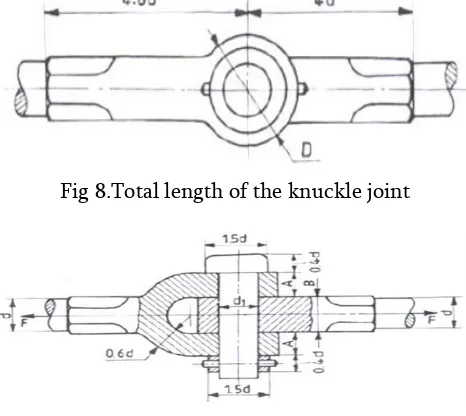
The following figure8.shows a knuckle indicating the dimensions. In general, the rods connected or if the rods are guided, they may support Let F. = tensile load to be resisted d = diameter of the rods d1 = diameter of the knuckle pin D = outside diameter of the eye A =thickness of the fork B =thickness of the eye Obviously, if the rods are made of B=2A Let the rods and pin are made of stresses. The following are the possible equations, which may be considered for t 1. Tension failure of the rod, across the section of diameter. The following figures shows a knuckle joint with the size parameters and proportions the rods connected by this joint are subjected to tensile loads, may support compressive loads as well. To be resisted by the joint = diameter of the knuckle pin e diameter of the eye are made of the same material, the parameters. Knuckle Joint are made of the same material, with σt , σc and τ as the permissible following are the possible modes of failure, and the corresponding may be considered for the design of the joint: Tension failure of the rod, across the section of diameter d, parameters and proportions to tensile loads, although are related as, B=2A
Fig 8.Total length of the knuckle joint
Fig9. Knuckle Joint
1. Tension failure of the rod, across the section of diameter, d
2. Tension failure of the eye
Tension failure of the eye 3. Tension failure of the fork
Tension failure of the fork
Shear failure of the eye
5. Shear failure of the fork
Shear failure of the fork
6. Shear failure of the pin. It is under double shear.
7. Crushing between the pin
8. Crushing between the pin and fork
For size parameters, not covered by the above design equations; proportions as indicated in the figure may be followed.
III. METHODOLOGY
INTRODUCTION TO CATIA
CATIA started as an in-house development in 1977 by French aircraft manufacturer Avions Marcel Dassault, at that time customer of the CADAM software to develop Dassault's Mirage fighter jet. It was later adopted in the aerospace, automotive, shipbuilding, and other industries.
Computer Aided Three dimensional Interactive Application(CATIA) is well known software for 3-d designing and modeling for complex
shapes.Commonly referred to as a 3D Product Lifecycle Management software suite, CATIA supports multiple stages of product development (CAX), including conceptualization, design (CAD), engineering (CAE) and manufacturing (CAM). CATIA facilitates collaborative engineering across disciplines around its 3DEXPERIENCE platform, including surfacing & shape design, electrical, fluid and electronic systems design, mechanical engineering and systems engineering.CATIA facilitates the design of electronic, electrical, and distributed systems such as fluid and HVAC systems, all the way to the production of documentation for manufacturing.
INTRODUCTION TO ANSYS
The ANSYS program allows engineers to construct computer models or transfer CAD models of structures, products, components, or systems, apply loads or other design performance conditions and study physical responses such as stress levels, temperature distribution or the impact of lector magnetic fields.
In some environments, prototype testing is undesirable or impossible. The ANSYS program has been used in several cases of this type including biomechanical applications such as high replacement intraocular lenses. Other representative applications range from heavy equipment components, to an integrated circuit chip, to the bit-holding system of a continuous coal-mining machine.
ANSYS design optimization enables the engineers to reduce the number of costly prototypes, tailor rigidity and flexibility to meet objectives and find the proper balancing geometric modifications.
and manufacturing costs and by giving engineers added confidence in the products they design. FEA is most effective when used at the conceptual design stage. It is also useful when used later in manufacturing process to verify the final design before prototyping.
MODELING:
Fig10.Assembly View 1
Fig11. Assembly View 2
Fig12.Assembly View 3
IV.RESULTS
The following are the analysis part of the knuckle joint by using ANSYS for different materials such as copper alloy and structural steel and magnesium alloy
COPPER ALLOY RESULTS
Fig13.Total deformation of the knuckle joint which is formed by copper alloy material
Fig14.Equivalent stress analysis of the knuckle joint formed by copper alloy material
Fig15. Shear stress analysis of the knuckle joint prepared by copper alloy material
Fig16. Equivalent Elastic strain analysisof the knuckle joint prepared by copper alloy material
MAGNESIUM ALLOY RESULTS
Fig17.Total deformation of the knuckle joint formed by magnesium alloy material
Fig19.Shear stress analysis on the knuckle joint in which magnesium alloy material
Fig20.Equivalent Elastic strain analysis of the knuckle joint using magnesium alloy material
STRUCTURAL STEEL RESULTS
Fig21.Total deformation of the knuckle joint formed by using structural steel material
Fig22. Equivalent stress analysis of the knuckle joint using structural steel material
Fig23.Shear stress analysis of the knuckle joint formed by structural steel material
Fig24. Equivalent Elastic strain analysis of the knuckle joint using structural steel material.
COMPARISON OF THREE MATERIALS
S. No
Material Total Deformation In mm
Equivalent Stress Analysis In Mpa
Shear Stress in MPa
Equivalent Elastic Strain
Analysis 1 Copper Alloy 0.04557 33.644 8.564 0.0007588 2 Magnesium Alloy 0.11125 33.665 8.5455 0.0007588 3 Structural Steel 0.025144 33.572 8.635 0.0001704
V. CONCLUSION & FUTHER SCOPE
CONCLUSION
Parts made out of composite materials are economical to produce, and facilitate overall systems cost reductions, due to avoiding the costly materials for better properties; it is eliminated by alloying with other materials.
From the above results and discussion, Knuckle joint was design for 50KN axial load by theoretical calculation. Final dimensions from theoretical calculation, model of Knuckle joint is made in CATIA V5 and model is taken to ANSYS and simulated with various material and check for best material which suit for given design load.
When compare with the three materials the structural steel has the low deformation and equivalent stress. It has the better shear strength and low elastic strain.Based on the above results structural steel will gives the best performance in all categories.
FUTHER SCOPE
The knuckle joint is the part of an automobile; it has to work always with more torque and high speed conditions. The design of the knuckle joint has to do with lighter materials for the betterment of the efficiency of the joint at the same time it has to possess high strength for the required working conditions. Almost the design modifications are not differ more for the previous one but more research has to do on the better materials for the better performance while in working.
VI. REFERENCES
[1]. Vinod M A. Kenaawy, A.M. Abdel Fattah, N.Okasha and M.EL-Gazery, Egypt. "Mechanical and structural properties of Ductile Cast Iron" Sol , vol. (24), No. (2), 2001
[2]. MIL-HDBK-"Composite material hand book"17- 5 volume 5 of 5, 17 June 2002.
[3]. V A. Soloukhin,W. Posthumus, J.C.M.Brokken-Z ijp, J. Loos, and G. de With: Polymer, Vol. 43 (2002), pp. 6169.
[4]. Shaikh J, vanka H, "Modeling and analysis of knuckle joint", international journal & magazine of engineering, technology, management and research,ISSN No: 2348-4845 vol. 2, issue 11, [2015], page no 292-298
[5]. Saxena N, Rajvaidya R, "Study and analysis of knuckle joint with the replacement of material by using Teflon", journal of engineering research & application, vol. 5, issue 3, [2015],page no 67- 71
[6]. Shinde D, kalita k, "FE analysis of knuckle joint pin used in tractor trailer", Asian research publishing network, vol. 10, [2015],page no 2227-2232
[7]. "Design of machine element",V.B Bhandari 3rd edition, McGraw Hill Education (India) Private Ltd, New Delhi
[8]. Das s, Bartaria v, pandey p, "Analysis of knuckle joint of 30C8 steel for automobile application", international journal of engineering research & technology,ISSN NO.2278-0181 vol. 3, issue 1, [2014],page no 235-242.
[9]. "Introduction to Finite Element in Engineering", Chandrapatala -3rd Edition, Prentice Hall of India, Belgundu.
[10].Harakal S, Avadhani R, Goud S, "Structural static analysis of knuckle joint ", international journal of engineering research and General science,ISSN NO.2091-2730 vol. 4, issue 2, [2016] page no 176-182.
[11].R. C. Juvinall, K. M. Marshek, "Fundamental of Machine Component Design," John wiley& sons Inc. 1999.
Fiat, chassis and body design and advanced process technologies dept., Italy, vol. 18, no. 1, pp. 19-23, 2000.
[13].K. S. Chang, P. S. Tang, "Integration of Design and Manufacturing of Structural Shape Optimization," Advances in engineering software, vol. 32, pp. 555-567, 2001.
[14].R. Roy, S. Hinduja and R. Teti, "Recent Advances in Engineering Design Optimization: Challenges and Future Trends," CIRP Annals Manufacturing Technology, pp. 697-715, 2008. [15].R. L. Jhala, K.D. Kothari, S. S. Khandare,
"Component Fatigue Behavior and Life Predictions of Steering Knuckle using Finite Element Analysis," vol. 2, pp.18-20, 2009. [16].W.M.W.Muhammad,E.Sujatmika,H.Hamid&F.
Tarlochan,"Design Improvement ofSteering Knuckle Component using Shape Optimization," International Journal of Advanced Computer Science, vol.2, no.2, pp. 65- 69, 2012.
[17].M. Azizi, M. Nora, H. Rashida, W. M. F. W. Mahyuddinb, "Stress Analysis of a Low Loader Chassis. International Symposium on Robotics and Intelligent Sensors," Procedia Engineering, 41, pp. 995-1001, 2012.
Cite this article as :


![Formation of Metal Silicide and Metal Germanosilicide Contacts to Si[subscript 1-x]subscript Ge[subscript x] Alloys](data:image/gif;base64,R0lGODlhAQABAIAAAP///wAAACH5BAEAAAAALAAAAAABAAEAAAICRAEAOw==)