e-ISSN: 2278-067X, p-ISSN: 2278-800X, www.ijerd.com
Volume 12, Issue 7 (July 2016), PP.10-16
Experimental Study on Performance of Composite Beams with
and without Shear Reinforcement
Neelima Khare
1, V. S. Shingade
21PG Student, Trinity College of Engineering & Research, Pune. 2Assistant Professor, Trinity College of Engineering & Research, Pune.
Abstract:-
This paper presents the experimental analysis of encased composite beam with and without shear reinforcement. The study revealed that ultimate tensile strength of composite beam is increased as compared to reinforced cement concrete beams. Reinforced concrete beams with and without shear reinforcement is compared with encased composite beam with and without shear reinforcement. The effect of change in stirrups spacing is studied experimentally. For this study, the cross sectional dimensions of the beam, percentage of tension reinforcements and grade of concrete are kept the same and spacing of stirrups is varied. Failure mode was studied which revealed that composite beams fails mainly by diagonal shear failure due to enhanced shear strength of beams. The study revealed that shear force is more at the supports but shear taken by concrete for a particular grade of concrete is constant, hence it is advisable to provide shear reinforcement. It was observed from experimental results that concrete and transverse reinforcement when combine together provide shear resistance to concrete encased composite beamsKeywords:-
Composite Beams, Rolled Steel Sections – Angle Section and Channel Section, Flexure and Shear StrengthI.
INTRODUCTIONThe concrete encased steel beams carry the merits of individual material by overcoming the limitation of each material and hence are effective in resisting higher loads. Preventing shear failure is major cause of concern for structural engineers while designing composite members. The shear failure mode in composite beam is mainly due to diagonal shear failure. This failure almost resembles the failure mode of ordinary reinforced concrete beams. Composite beams have various forms. The present experimental research was conducted on composite beams encased with rolled steel sections as main reinforcement with with and without shear reinforcement and results obtained were compared with normal tmt steel reinforced beams. Earlier investigations have shown that shear force is more near supports, but shear taken by concrete is same for a particular grade of concrete. The shear stress is more near supports due to increased Shear Force which in turn give rise to diagonal cracks near support As we all know concrete is inefficient in resisting tension so high tensile stresses develop which exceeds the low tensile strength of concrete. Diagonal shear cracks develop near supports. The shear failure of composite beams is associated with following stages:
Flexure cracks developing on the tension zone and extending in a vertical direction. This is due to the fact that bending moment is large and shear force is small. The tensile stresses reach the tensile strength of concrete which is very low and hence cracks develop in the tension zone. Such cracks are known as flexure cracks.
Near the quarter span bending moment and shear force are also significant, the cracks are initiated in the tension zone due to flexure and gradually tends to develop in the inclined direction due to increase in shear stress. Such cracks develop under combined action of shear and flexure.
Near the support where shear force is predominant, shear stress is maximum hence diagonal cracks develop in the tension zone.
II
AIMS AND OBJECTIVE
Aim:
To study the performance of composite beams under shear and flexure with and without shear reinforcement.
Objective:
Study of confinement of concrete by stirrups in composite beam with rolled steel section and beams with normal tmt steel
To study effect of Rolled steel angle section and channel section as main reinforcement on ultimate load carrying capacity and deflection.
The variables parameter included in this study is:
Spacing of Stirrups i.e. confinement effect.
The Constant parameters included in this study are as follow:
Percentage of steel
Cross sectional area of member Grade of concrete – M20
All the beam sections are under-reinforced
Dimensions of Beams:
Size of beam adopted: 150 mm x 150 mm x 700 mm. Breadth (b) = 150 mm
Depth (D) = 150 mm
Effective depth = 150 - 25 - (12/2) = 119 mm
Nomenclature:
Following members are recognized for experimental investigation: B1: Beam with Normal ie. Conventional tmt steel reinforcement. B2: Beams with rolled steel Angle sections as reinforcement. B3: Beams with rolled steel Channel sections as reinforcement.
II.
EXPERIMENTAL
PROGRAM
In order to study the shear behavior of beams 12 specimens each of B1, B2, B3 were casted and tested in UTM Machine. The two point load was applied at the middle third portion of the beam. The load was applied gradually and crack pattern was observed. Load at first crack, yield load and failure load along with corresponding deflection were observed. Graph of load v/s deflection was plotted. Hence the load carrying capacities and deformations for beams with rolled steel sections as main reinforcement were studied and compared with normal reinforced cement concrete-beams.
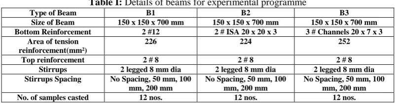
Table I: Details of beams for experimental programme
Type of Beam B1 B2 B3
Size of Beam 150 x 150 x 700 mm 150 x 150 x 700 mm 150 x 150 x 700 mm Bottom Reinforcement 2 #12 2 # ISA 20 x 20 x 3 3 # Channels 20 x 7 x 3
Area of tension reinforcement(mm²)
226 224 252
Top reinforcement 2 # 8 2 # 8 2 # 8
Stirrups 2 legged 8 mm dia 2 legged 8 mm dia 2 legged 8 mm dia
Stirrups Spacing No Spacing, 50 mm, 100 mm, 200 mm
No Spacing, 50 mm, 100 mm, 200 mm
No Spacing, 50 mm, 100 mm, 200 mm
No. of samples casted 12 nos. 12 nos. 12 nos.
In a reinforced concrete sections when concrete and steel reaches the yield stage simultaneously then the section is termed as balanced section. In a reinforced concrete when concrete reaches the yield strain earlier than that of steel, than the section is over reinforced. Such sections fail by compression failure of concrete without much warning and with very few cracks and negligible deflections. Over reinforced concrete beams are not preferred since they require large quantities of steel and they fail suddenly with explosive failures without any warning. In under reinforced section, the tension steel reaches yield strain at loads lower than the load at which concrete reaches the failure strain. When the steel yields earlier than concrete there will be excessive deflections and cracking with a clear indication of impending failure. The beams B1, B2 and B3 are under- reinforced because it is preferable to design beams as under reinforced since failure will take place after yielding of steel with clear warning signals like excessive deflections and cracking before the ultimate failure.
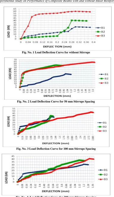
Fig. No. 1 Load Deflection Curve for without Stirrups
Fig. No. 2 Load Deflection Curve for 50 mm Stirrups Spacing
Fig. No. 3 Load Deflection Curve for 100 mm Stirrups Spacing
Fig. No. 4: Load Deflection Curve for 200 mm Stirrups Spacing
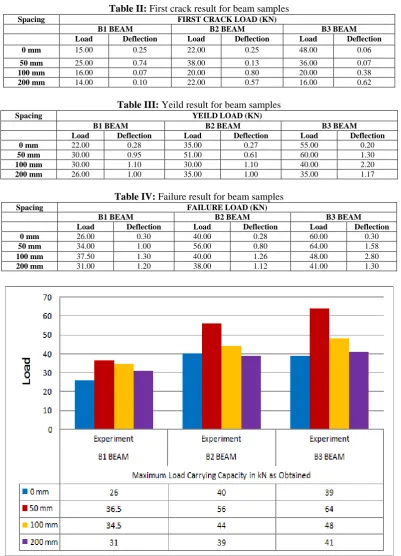
of cross section of beams but with rolled steel sections as bottom reinforcement, it is observed that load carrying capacity is increased as compared to B1 beams. It is obvious from the graphs above that as the spacings between stirrups is reduced the load carrying capacity is increased. For B1 type beam specimen, the load carrying capacity is 26 kN for without stirrups ie without shear reinforcement : 31kN for 200 mm spacing; 34.5 for 100 mm spacing; 36.5 for 50 mm spacing. For B2 type beam specimen, the load carrying capacity is 40 kN for without stirrups ie without shear reinforcement: 41 kN for 200 mm spacing; 48 for 100 mm spacing; 64 for 50 mm spacing. For B3 type beam specimen, the load carrying capacity is 39 kN for without stirrups ie without shear reinforcement; 39 kN for 200 mm spacing; 44 for 100 mm spacing; 56 for 50 mm spacing. This shows that confinement effect of concrete in the form of stirrups spacing has improved the load carrying capacity of beams, which in turn increases the shear strength and flexure strength of beam specimen.
The B2 and B3 type beams are more effective in resisting higher loads as compared to B1 Type beam specimen. It is observed that ultimate strength of B2 & B3 beam specimen is increased. This indicates that shear force is increased but shear taken by concrete for M20 grade is fixed. Hence to account for additional shear force near support we need to provide shear reinforcement. Also the shear force acting on the section is greater than shear capacity of concrete, as a result diagonal cracks emerges. In order to prevent the formation of the diagonal cracks and its widening, additional shear reinforcement is required to prevent shear failure.
III.
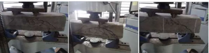
CRACKPATTERNFORBEAMSFor B1, B2 and B3 beams without shear reinforcement, the shear cracks were observed in the support region, when the load was in the range of 50 to 80 % of the failure load. Eventually the beams tend to fail due to crushing of concrete in compression zone along the diagonal direction.
For B2 and B3 beams without shear reinforcement, there was increase in crack width. This is due to the reason that shear strength taken by concrete is constant for M20 grade of concrete and ultimate load carrying capacity is increased which in turn increases shear force. Hence at the verge of failure the major cracks become unstable and the cracks propagate rapidly to fail the beam in diagonal shear.
For B1, B2 and B3 beams with shear reinforcement at 50 mm, 100 mm and 200 mm spacing, the width of cracks is considerably reduced due to the confinement of concrete with transverse reinforcement.
Hence shear strength of concrete is increased with the confinement effect of stirrups. As we go on reducing the stirrups spacing the shear strength is increased. This further increases the ductility of beams with shear reinforcement.
Crack pattern for beams with shear reinforcement
Fig. No. 6: crack pattern for B1, B2, B3 beams with shear reinforcement (100 mm spacing) Crack pattern for beams without shear reinforcement
IV.
RESULTS
AND
DISCUSSION
a) There was increase in shear strength of B2 and B3 beams as compared to B1 beams. b) As the spacing of stirrups is decreased, the shear strength of beams is increased. c) The confinement effect of stirrups has increased the shear strength of concrete.
d) A typical diagonal crack pattern was observed in almost all types of beam samples. The crack width observed is more in beams without shear reinforcement as compared to beams with shear reinforcement. e) B2 beams encased with angle section performs better in terms of shear strength, load carrying capacity and
deflection as compared to B1 and B3 beams.
Table II: First crack result for beam samples
Spacing FIRST CRACK LOAD (KN)
B1 BEAM B2 BEAM B3 BEAM
Load Deflection Load Deflection Load Deflection
0 mm 15.00 0.25 22.00 0.25 48.00 0.06
50 mm 25.00 0.74 38.00 0.13 36.00 0.07
100 mm 16.00 0.07 20.00 0.80 20.00 0.38
200 mm 14.00 0.10 22.00 0.57 16.00 0.62
Table III: Yeild result for beam samples
Spacing YEILD LOAD (KN)
B1 BEAM B2 BEAM B3 BEAM
Load Deflection Load Deflection Load Deflection
0 mm 22.00 0.28 35.00 0.27 55.00 0.20
50 mm 30.00 0.95 51.00 0.61 60.00 1.30
100 mm 30.00 1.10 30.00 1.10 40.00 2.20
200 mm 26.00 1.00 35.00 1.00 35.00 1.17
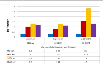
Table IV: Failure result for beam samples
Spacing FAILURE LOAD (KN)
B1 BEAM B2 BEAM B3 BEAM
Load Deflection Load Deflection Load Deflection
0 mm 26.00 0.30 40.00 0.28 60.00 0.30
50 mm 34.00 1.00 56.00 0.80 64.00 1.58
100 mm 37.50 1.30 40.00 1.26 48.00 2.80
200 mm 31.00 1.20 38.00 1.12 41.00 1.30
Fig. No. 7: Maximum Deflection for B1, B2, B3 beams with and without shear reinforcement
V.
CONCLUSION
A typical diagonal crack pattern indicates diagonal shear failure in almost all types of beam samples. The crack width observed is more in beams without shear reinforcement as compared to beams with shear
reinforcement.
The shear strength of B2 and B3 beams is more than B1 beams.
Ductility of beams is increased by providing shear reinforcement. Beams without shear reinforcement fail due to crushing of concrete in diagonal tension.
Beams with shear reinforcement has favourable effect on shear strength due to confinement of concrete by transverse reinforcement in the form of stirrups.
As we go on reducing the spacing the shear strength is increased.
The deflection of beam at ultimate load decreases as the spacing between stirrups is decreased.
Though the shear failure is visualised as brittle in B1 type beams but in B2 & B3 beams the test results revealed ductile behaviour under controlled deflection.
REFERENCES
[1]. Mrs. V. S Sohoni, “Behaviour of Concrete Encased Steel Composite Members of Framed Structure.” December 2012.
[2]. CorradoChisari, Claudio Amadio – “An experimental, numerical and analytical study of hybrid RC-encased steel joist beams subjected to shear”, Engineering Structures – ELSEVIER, 2014.
[3]. Shun-ichi Nakamura, Naoya Narita – “Bending and shear strengths of partially encased composite I-girders”, Journal of constructional steel research - ELSEVIER, 2003
[4]. Moataz Awry Mahmoud , Tamer Hassan Elafandy , Hussein Osama Okail ,Amr Ali Abdelrahman – “Interfacial shear behavior of composite flanged concrete beams”, HBRC Journal, 2013
[5]. Daniel Lowe, Raj Dasa, Charles Clifton – “Characterization of the splitting behavior of steel-concrete composite beams with shear stud connection” ,Procedia Materials science ELSEVIER, 2014
[6]. JianguoNie; Yan Xiao; and Lin Chen – “Experimental Studies on Shear Strength of Steel–Concrete Composite Beams”, Journal of structural Engineering, 2004.
[7]. C. C. Weng; S. I. Yen; and M. H. Jiang – “Experimental Study on Shear Splitting Failure of Full-Scale Composite Concrete Encased Steel Beams”, Journal of structural Engineering, 2002.
[8]. R.A. Barnes , P.S. Baglin , G.C. Mays , N.K. Subedi – “External steel plate systems for the shear strengthening of reinforced concrete beams”, Engineering Structures – ELSEVIER, 2000.
[9]. Leopoldo Tesser, Roberto Scotta – “Flexural and shear capacity of composite steel truss and concrete beams with inferior precast concrete base”, Engineering Structures – ELSEVIER, 2012.
[11]. Chao Liu – “Research on Property of Steel-Encased Concrete Composite Beams with superior Performance”, International journal of computer trends and technology, 2013
[12]. Jun He, Yuqing Liu, ZhaofeiLin ,Airong Chen , Teruhiko Yoda – “Shear behavior of partially encased composite I-girder with corrugated steel web: Numerical study”, Journal of constructional steel research - ELSEVIER, 2014.
[13]. By C. C. Weng, S. I. Yen, and C. C. Chen – “Shear strength of concrete encased - composite structural members”, Journal of structural Engineering, 2001.
[14]. By Deric John Oehlers – “Splitting induced by shear connectors in composite beams”, Journal of structural Engineering, 1989
[15]. Herbert K. Schilger (Canada), “US patent with design registration no.4905440”, and date of issue of Patent: march 6, 1990.
[16]. Mr.Vincent, Mr.Richard (Canada), “US patent with design registration no.6061992”, and date of issue of Patent: march 16, 1998.
[17]. Sherif-El-tawil, Gregory G.Deierlein, “Strength and Ductility of concrete encased Composite column”, Journal of Structural Engineering, Vol 125 no. 9 pp 1009 – 1019, September 1999.