IJIRSE/2017/Vol 5. Iss. 1/ Page 17
New Algorithm for Solving Problem of Image Shifting In
Scanning Processing
Mohammed Mubarak Salih, Nahlah M.A.M.Najm
Computer Technical Department, Al-Rafidain University College, Baghdad, Iraq
Abstract—There are many methods to deal with pixel shifting one of them is scan conversion; given a polygon in image space, this process determines the pixels that intersect the polygon. This process is utilized in visible-surface algorithms, incremental-shading techniques, polygon-fill algorithms, ray-tracing-acceleration algorithms, and a number of other tasks that are critical to the understanding of the computer graphics field. This paper suggest anew algorithm for solving the problem of shifting pixel in an image after the scanning process by adapting the technique of rotation the image in X-axis and Y-axis, further more we calculate the slope of shifting in an image and dividing the image into fake triangles to calculate the position of pixels after shift. To prove the effectiveness of the suggested algorithm we implement it on an offline examination by use a stander form of answer sheet which is scanning and use the scanning image to check the answer of student. After scanning the answer sheet a problem of shifted in image was found.
Keyword: Image Shifting, , incremental-shading techniques, polygon-fill algorithms,
ray-tracing-acceleration algorithms1.INTRODUCTION
Computer graphics (CG) is commonly understood to mean the creation, storage and manipulation of models and images. Such models come from a diverse and expanding set of fields including physical, mathematical, artistic, biological, and even conceptual (abstract) structures [1,2].
A digital image is a representation of a two-dimensional image as a finite set of digital values, called picture elements or pixels. Pixel values typically represent gray levels, colors, heights, opacities etc. Image processing is the analysis of scenes or reconstruction of model of 2D or 3D objects from their pictures. Simple image processing can be used in CG to help synthesize the image of a model. Also combining and transforming synthetic images depends largely on image processing operations [5].
Computer graphics deals with: Imaging (representing 2D images) Geometric modeling (creating mathematical models of 2D and 3D objects), Rendering (producing images given these models) and Animation (defining/representing time dependent behavior of objects) [3].
The term rasterisation in general can be applied to any process by which vector information can be converted into a raster format. The process of rasterising 3D models onto a 2D plane for display on a computer screen is often carried out by fixed function hardware within the graphics pipeline. The final step in the traditional rasterisation process is to fill in the 2D triangles that are now in the image plane. This is also known as scan conversion [5].
A. Rasterisation (or rasterization)
Is the task of taking an image described in a vector graphics format (shapes) and converting it into a raster image (pixels or dots) for output on a video display or printer, or for storage in a bitmap file format. In normal usage, the term refers to the popular rendering algorithm for displaying three-dimensional shapes on a computer [1]. Rasterisation is currently the most popular technique for producing real-time 3D computer graphics. Compared with other rendering techniques such as ray tracing, rasterisation is extremely fast. However, rasterisation is simply the process of computing the mapping from scene geometry to pixels and does not prescribe a particular way to compute the color of those pixels. The most basic rasterisation algorithm takes a 3D scene, described as polygons, and renders it onto a 2D surface, usually a computer monitor. Polygons are themselves represented as collections of triangles. Triangles are represented by 3 vertices in 3D-space. At a very basic level, rasterisers simply take a stream of vertices; transform them into corresponding 2-dimensional points on the viewer’s monitor and fill in the transformed 2-dimensional triangles as appropriate [4,7].
IJIRSE/2017/Vol 5. Iss. 1/ Page 18
Transformations are usually performed by matrix multiplication. The main transformations are translation, scaling, and rotation. A three-dimensional vertex may be transformed by augmenting an extra variable (known as a "homogeneous variable") and left multiplying the resulting 4-component vertex by a 4 x 4 transformation matrix [5,6].
A translation is simply the movement of a point from its original location to another location in 3-space by a constant offset. Translations can be represented by the following matrix:
X, Y, and Z are the offsets in the 3 dimensions, respectively.
A scaling transformation is performed by multiplying the position of a vertex by a scalar value. This has the effect of scaling a vertex with respect to the origin. Scaling can be represented by the following matrix:
X, Y, and Z are the values by which each of the 3-dimensions is multiplied. Asymmetric scaling can be accomplished by varying the values of X, Y, and Z.
Rotation matrices depend on the axis around which a point is to be rotated. Rotation about the X-axis:
Rotation about the Y-axis:
Rotation about the Z-axis:
θ in all each of these cases represent the angle of rotation.
A series of translation, scaling, and rotation matrices can logically describe most transformations. Rasterisation systems generally use a transformation stack to move the stream of input vertices into place. The transformation stack is a standard stack which stores matrices. Incoming vertices are multiplied by the matrix stack [1].
IJIRSE/2017/Vol 5. Iss. 1/ Page 19
Scan Conversion is the process of finding the screen pixels that intersect a polygon. To do this, it is convenient to move to a copy of image space that is scaled to closely correspond to the pixels in the display window [3]. This space, commonly called device space is parameterized so that the lower-left-hand corner is at (0, 0), and so that the pixels can all be indexed by integers. To scan convert a polygon in this space, the polygon is split into a set of trapezoids as is shown below, and then scan convert each trapezoid. Each trapezoid will be of a special form where the top and bottom edges of the trapezoid are parallel to the scan lines (i.e., of a constant y value) [5].
II. SUGGESTION SHIFTING ALGORITHM
To implement the shifting algorithm some point must be consider
First the location of point (X1,Y1) are calculated it will have illustrated in step IV
Second the distance between point(X1,Y1) and point (X2,Y2) are known in design of blank stander answer sheet. This led to know the location of point(X2,Y2)
Third slope is calculating from two corner point left (XCR, YCR) and right (XCL,YCL) where s slope=(YCL-YCR)/(XCL-XCR) .
Shifting image up meant decrease in Y and decrease in X let flag=1 it will have illustrated in step I and step II Fourth the distance between point (X1,Y1) and shifting point of (X2,Y2) is same distance between point(X1,Y1) and point (X2,Y2) without shift
To calculate the location of point (X2,Y2) after shifting in Figure 1 we use the following equations
e
= + = + where =
, + = + where =
L
slope=0
X1,Y1 X2,Y2 flag=0
slope =+v L D2 flag=-1
(X1,Y1) D1 (X2,Y2)
(X1,Y1) D1
slope=-v D2 flag=+1 L
IJIRSE/2017/Vol 5. Iss. 1/ Page 20 X2=X1+Lcos
Y2=Y1+flag*Lsin
Suggestion Shifting Algorithm
A. Calculate the four corner of sheet 1: Calculate the upper left corner (XC1, YC1)
To find value of YC1 in left corner start at location (X, Y) of value (minx+250, miny). Read pixel if its white increase Y=Y+1 repeat this until find black pixel and record the value of YC1.
To find value of XC1 in left corner start at location (X, Y) of value (minx, YC1+250). Read pixel if its white increase X=X+1 repeat this until find black pixel and record the value of XC1.
2: Calculate the upper right corner (XC2, YC2)
To find the value of YC2 in right corner start at location (X, Y) of value (maxx-250, miny). Read pixel if its white increase Y=Y+1 repeat this until find black pixel and record the value of YC2.
To find value of XC2 in right corner start at location (X, Y) of value (maxx, YC2+250). Read pixel if its white decrease X=X-1 repeat this until find black pixel and record the value of XC2.
3: Calculate the lower left corner (XC3, YC3)
To find value of YC3 in left corner start at location (X, Y) of value (minx+250, maxy). Read pixel if its white decrease Y=Y-1 repeat this until find black pixel and record the value of YC3.
To find value of XC3 in left corner start at location (X, Y) of value (minx, YC3-250). Read pixel if its white increase X=X+1 repeat this until find black pixel and record the value of XC3.
4: calculate the lower right corner (XC4, YC4)
To find value of YC4 in right corner start at location (X, Y) of value (maxx-250, maxy). Read pixel if its white decrease Y=Y-1 repeat this until find black pixel and record the value of YC4.
To find value of XC4 in right corner start at location (X, Y) of value (maxx, YC4 -250). Read pixel if its white decrease X=X-1 repeat this until find black pixel and record the value of XC4.
B. Find the shift direction and value of slope
1: if (XC1 == XC2) In this case no shifting is found flag=0 2: if (XC1>XC2) In this case shift is down flag=-1 3: if (XC1< XC2) In this case shift up flag=1 4: slope= (YC2-YC1) / (XC2-XC1)
C. Find the value of information1 array and information2 array. Each of them are two-dimension array 10 row and 2 columns
To find all element of information1
1: To record fist element (Xinf1, Yinf1) Start by value of Y=400 and X=XC1+100). Read pixel if its white increase Y=Y+1 repeat this until find black pixel and record the value of Yinf1.
To find value of Xinf1 start at location (XC1+100, Yinf1-10). Read pixel if its white increase X=X+1 repeat this until find black pixel and record the value of Xinf1.
2: To record (Xinf2, Yinf2) Start by value (Xinf1-10, Yinf1+10). Read pixel if its white increase Y=Y+1 repeat this until find black pixel and record the value of Yinf2
To find value of Xinf2 start at location (Xinf1 -10, Yinf2-10). Read pixel if its white increase X=X+1 repeat this until find black pixel and record the value of Xinf2.
3: Record the rest eight point of information1 array as in step 2
IJIRSE/2017/Vol 5. Iss. 1/ Page 21
D. Find the value of answer1, answer2, answer3 and answer4 each of them are two dimension arrays of two columns and 25 rows
1: To record fist element (Xans1, Yans1)
To find Yans1 Start (Xinf10 -20, Yinf10+20). Read pixel if it's white increase Y=Y+1repeat this until find black pixel and record the value of Yans1.
To find value of Xans1 start at location (Xinf10-20, Yans1-10). Read pixel if its white increase X=X+1 repeat this until find black pixel and record the value of Xans1.
2: To record (Xans2, Yans2) Start by value (Xans1-10, Yans1+10). Read pixel if its white increase Y=Y+1repeat this until find black pixel and record the value of Yans2
To find value of Xans2 start at location (Xans1 -10, Yans1-10). Read pixel if its white increase X=X+1 repeat this until find black pixel and record the value of Xans2.
3: record the rest 23 point of answer1 array as in step 2
To record answer2, answer3 and answer4 do the same think as answer1 each with different initial point for X and Y.
E. Calculate value of any answer or information 1: To read any selected point figure 1
Using the recording location of any answer as initial point ( , ).To calculate the location of answer point after shift (X2, Y2). This is done by using the shifting question. X2 and Y2 was use to read pixel if it's white record 0 and record 1 if it's not white. Combination the five point in answer sheet and convert them decimal value and store it.
F. record mark of student
1: record value of lecturer answer by use answer sheet of lecturer And record it's in answer lecturer array.
2: use student sheet to record student number or any necessary information 3: record value of student answer by use answer sheet of student
And record it's in answer student array.
4: compare array of lecturer and student to all question and calculate the marks of right answer III. Implementation offline examination
The implementation was done by five software models A. First models
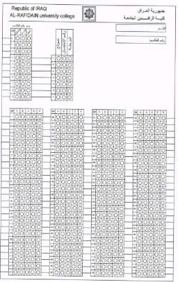
This model used to create stander answer sheet form. The answer sheet used in this paper content 100 question of type Multiple Choose Questions (MCQ). Which is used later by lecturer and students (figure 1).
B. Second model
This model is used to build bank of question of type MCQ and store it in Access database. Later this database is use to create lecturer answer sheet; by select number of question and recording each the answer in lecturer answer sheet.
This model is implemented in two stages: First stage is as background from user and is implemented by Microsoft access database. Second stage which is front used by user is implemented in visual basic 2010
C. Third model
This model is the main model used to fix the problem of shifting in the answer sheet. The left corner use as the origin of the X and Y axis. Then calculates the slope of the entire image depend on the left corner and right corner. Ideally the slope must be zero. In case of shifting ether the shifting up or shifting down. To calculate the location of each circle, calculate the slope for each circle depending on the left side as origin of each circle. Depend on slope direction ether adding or subtracting the difference from the original location. This was discussing in the first model.
First scanning the answer sheet of lecture for each question which has five chooses. We fix the problem of shifting pixel by using the implemented algorithm. Convert the answer to decimal value and store it's in array. Scanning student answer sheet also solve the shifting problem as the lecture sheet and convert it to decimal value and store it in another array. Compare the answer with lecture answer to calculate the score of each student
IJIRSE/2017/Vol 5. Iss. 1/ Page 22
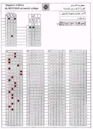
This model used to show the accuracy of reading pixel from the answer sheet. This was done by showing the four vertical red line where the student shadowing their answer and observe the resuilt by seeing (visualize by human eye).
E. Fifth model
This model used to show the result of examination. IV. Conclusions
In this paper, the problem of shifted image which content information has been solved by using the selected algorithm implemented in visual basic program. One of the major problem of reading an information from an image is the shifting that happen after the scanning the image. In this paper we adaptive offline examination to solve problem of shifting. This is done by designing a sheet which is use as a stander image as shown in figure (1). One sheet was used for lecturer and other used by students the result was record by compare the two answer. Observing the result was done in two stages. The first stage was done by test the program to small group of student. After the examination compering the result between hand marking and the program marking and we observe that the result was similar. Second stage when the number of student(image) increase the problem of checking the efficiency of result by hand will be more difficult. A solution was needed in this stage by modification to the program to check the result by see. In this modification we draw four vertical red line to the selected answer (shadowing) of student from the program and the selected of teacher (shadowing) by blue vertical line as show in figure(3A). This give ability to show all the checked image faster. There are many applications that use select information from image like record the result of an election system and residential census. The plan is to use this algorithm in Iraqi election system. Also the planning is going to modify the offline examination with other type of examination call Online examination which done on computer on line.
IJIRSE/2017/Vol 5. Iss. 1/ Page 23
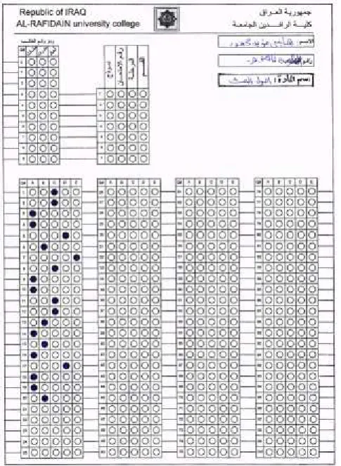
Figure 2/ answer sheet of student answer
IJIRSE/2017/Vol 5. Iss. 1/ Page 24
Figure 3/An answer sheet after checking
IJIRSE/2017/Vol 5. Iss. 1/ Page 25 References
[1] J. D. Foley, A. Van Dam, S. K. Feiner, J. F. Hughes, "Computer Graphics: Principles and Practice in C",Addison-Wesley, 2014
[2] Dave Shreiner, ,"OpenGL Programming Guide: The Official Guide to Learning OpenGL", Version 2, Addison-Wesley, 2006
[3] Eric Lengyel. Charles River Media, "Mathematics for 3D Game Programming & Computer Graphics", Cengage Learning, 2012
[4] 4-http://www.cs.brandeis.edu/~cs155
[5] Francis S. Hill ,"Computer Graphics", Prentice Hall,2001.
[6] M. Slater, A. Steed, Y. Chrysantho," Computer graphics and virtual environments: from realism to real-time", Addison-Wesley, 2002.