PLC BASED AUTOMATIC RAILWAY GATE CONTROLLER AND
OBSTACLE DETECTOR
Sayali V. Surve1, Sudhir S. Wamane2, Suhas H. Mhabadi3 & Milind N. Tagare4
1. INTRODUCTION
When it involves public and private safety, it is always desirable to improve the signaling system and the way people are warned about potentially dangerous situations. The existing conventional signaling system most of the times rely on the oral communication through telephonic and telegraphic conversation as input for the decision making in track allocation for trains. There is a large scope for miscommunication of the information or communication gap due to the higher human interference in the system [1]. This may cause the wrong allocation of the track for trains that ultimately results in the train collision. The statistics within the developing country showing that most of worst collisions occurred thus far are because of either human errors or incorrect decision making through miscommunication in signaling and its implementation. At railway crossing, the traditional railway system uses the warning lights and human controlled gates to alert the people about an oncoming train. When the train leaves the station, the station agent informs the gatekeeper regarding the arrival of the train using the telephone and telegraph. The gatekeeper closes the gate depending on the timing at which the train arrives. Hence, if the train is late because of certain reasons, then gate stay closed for an extended time inflicting traffic near the gates [2]. By victimization, the automatic railway gate control at the railway crossing the arrival of the train is detected by the sensing element placed on the track at a precise distance from the gate. This sensing element detects the approaching train and consequently controls the operation of the gate. When the wheels of the train moving over the track there will be position switch and it will send the signal to PLC to indicate train arrival. This reduces the time that gate is closed as compared to the gates operated manually. In addition, this also reduces the human labor. This sort of automatic railway gate system is employed in associate unmanned gate crossing where the probabilities of accidents are higher and reliable operation is needed.
2. BLOCK DIAGRAM
Figure 1 shows the block diagram of automatic railway gate controller in which two sensors are used on either end of the railway crossing for sensing the position of the train. When the train arrives at the level crossing, train position switch detects the arrival of the train and gives an output which acts as input to the PLC. Now the PLC activates the output, to which relay is connected.
1
Department of Electrical Engineering, FAMT Ratnagiri, Maharashtra, India
2 Department of Electrical Engineering, FAMT Ratnagiri, Maharashtra, India
3
Department of Electrical Engineering, FAMT Ratnagiri, Maharashtra, India
4
Department of Electrical Engineering, FAMT Ratnagiri, Maharashtra, India
International Journal of Latest Trends in Engineering and Technology
Vol.(9)Issue(3), pp.133-139
DOI: http://dx.doi.org/10.21172/1.93.23
e-ISSN:2278-621X
Abstract- The existing conventional railway crossing gate control systems are being operated manually. Thus, many accidents are being occurred due to the carelessness in manual operations or lack of workers. To avoid such accidents the proposed project will analyze few vulnerable areas of accidents and help to find out the possible way to reduce the number of accidents. This paper provides an automatic railway crossing gate replacing the gates operated by the workers. This project helps to reduce the time for which the gate is being kept closed and provide safety to the road users by reducing the accidents. In this work, an automatic railway crossing gate control system has been developed using a Programmable Logic Controller (PLC). For this purpose, we used Allen- Bradley Micrologix PLC and Rockwell software for PLC programming. Signaling light models are implemented using several red, green and yellow Light Emitting Diodes (LEDs); and railway gates are opened using DC motors with gear trains that are connected to the output ports of the PLC. For energizing different parts of the system and DC motors, separate DC power supplies have been designed.
Figure 1. Block diagram of PLC based railway gate controller and obstacle detector
This energizes the motor in the forward direction which is coupled to the gate assembly and closes the gate without manual control and the train continues to run. If there is obstacle present on a level crossing, obstacle detector switch gets pressed and sends a signal to train motor through PLC and the train gets stop [3]. If there is no obstacle then the train continues to run. When the train passes beyond the gate assembly, it opens for crossing purpose. The DC gear motor with brush is used for train movement, and they are in contact with track
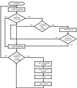
FLOW CHART –
Figure 2 shows the flowchart of automatic railway gate controller in which train position sensors are used on either end of the railway crossing to sense the position of the train and gives appropriate output to PLC. The obstacle detector senses any obstacle present on the level crossing and gives the signal to PLC. If any obstacle is present on the track then PLC will send stop command to geared DC motors which are used as wheels of the train, if the train is closer to an obstacle. Once the obstacle is removed from the track then PLC will send run command to geared DC motors. If no obstacle is present on the track at level crossing then the train will continue to run. For automatic railway gate opening and closing system, PLC takes the reference of train position sensors. If the train is closer to the level crossing, PLC activates its output and sends the close command through a relay to DC motors which are coupled to the railway gate assembly. This closes the railway gate assembly automatically. Once the train crosses the leveler, PLC activates its output to open the gate automatically after some delay.
3. HARDWARE SPECIFICATIONS
To implement this project, we need an personal computer (PC) installed with RS logix micro software, Allen Bradley PLC Micrologix 1400, 1766-L32BWAA series processor, resistors, DC motors and associated circuits to actuate the railway gate, various sensors to sense whether the train has passed the gate or not and whether the gate has opened or closed, connecting wires and DC power supplies etc.
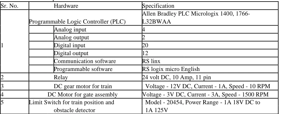
Table -1 Hardware Specifications
Sr. No. Hardware Specification
Allen Bradley PLC Micrologix 1400, 1766-
Programmable Logic Controller (PLC) L32BWAA
Analog input 4
Analog output 2
1 Digital input 20
Digital output 12
Communication software RS linx
Programmable software RS logix micro English
2 Relay 24 volt DC, 10 Amp, 11 pin
3 DC gear motor for train Voltage - 12V DC, Current - 1A, Speed - 10 RPM 4 DC Motor for gate assembly Voltage - 3V DC, Current - 3A, Speed - 1500 RPM 5 Limit Switch for train position and Model - 20454, Power Range - 1A 18V DC to
obstacle detector 1A 125V
The PC is used to write, edit, compile, debug and then finally to download the program into the PLC processor. The PC's serial port (COM1) is connected to the PLC’s DIN socket by a 9 pin serial connector. At that time, the PLC must be in PROG mode [4]. After downloading the program PC is no Ionger required. Then the PLC is set in a RUN mode to send the output signals to its output ports. Separate DC power supplies are designed using regulated power supply IC LM317. There are two DC geared motor used for this project which is for movement of train wheels. These motors are coupled to the wheels of the train and they are connected with track through brushes. The DC geared motors are used to reduce the speed of the train at the proper level. Limit switches are used to detect the obstacle and position of the train. These switches work as the system input to inform the programmable logic controller (PLC) regarding the current situation of the system (train position).When there’s an obstacle on track, the limit switch gets pressed and PLC receives the input signal. For railway gate mechanism DC motors are used. When the train reaches at position switch 5, the switch gets pressed. The signal goes to the PLC and according to the PLC programming gates closed. When the train reaches at position switch 1, the switch gets pressed, in step with the PLC programming gates opened. Two relays are used for Forward/Reverse train direction and two for open/close the gate. When relay one is turning on by the PLC according to instruction, it will change the polarity so that the motor will have the potential difference to make it running in one direction. This operation is same when relay two was turning on by PLC in other situation to make it run in other direction. Single pole double through types of relay are used for this project with relay voltage of 24 volts.
4. PLC PROGRAMMING
Table -2 PLC Input and Output Addresses Input Addresses Train position switch
Limit Switch 1 (Position 1) I:0/1 Limit Switch 2 (Position 2) I:0/2 Limit Switch 3 (Position 3) I:0/3 Limit Switch 4 (Position 4) I:0/7 Limit Switch 5 (Position 5) I:0/8 Obstacle Detector Switch
Limit Switch 1 (Obstacle Detector 1) I:0/9 Limit Switch 2 (Obstacle Detector 2) I:0/10 Limit Switch 3 (Obstacle Detector 3) I:0/11 Limit Switch 4 (Obstacle Detector 4) I:0/12 Limit Switch 5 (Obstacle Detector 5) I:0/13
Output Addresses
Train Motor (Forward) O:0/1
Train Motor (Reverse) O:0/2
Gate Assembly Motor (Closing) O:0/3 Gate Assembly Motor (Opening) O:0/4
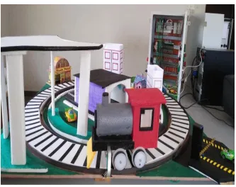
Experimental Setup
4. CONCLUSION
The accidents can be avoided up to a great extent and also the human resource that was previously used to just close and open the gate is additionally replaced by PLC based railway gate controller and obstacle detector. Here we used DC motors to open and close the gates automatically by its rotation in anticlockwise and clockwise directions respectively. Whenever the train arrives from a specific direction the proximity sensor provides the signal to PLC and it generates an acceptable signal for the operation of DC motor to close/open the gate. PLC sends operating signal to the dc motors according to the output signal of sensors to open/close the railway crossing gate. In our project, we used obstacle detector switch which saves the life of obstacle, so safety is increases. A prototype road and rail line model with railway gate have been created and enforced within the laboratory. After successful laboratory testing of the complete system, it was found that the developed system operates satisfactorily.
5. REFERENCES
[1] M. M. Hossain and S. S. Mostafa, “A Radio-Based Railway Crossing Control System to Reduce Accident”, Engineering Research, Innovation and Education (CERIE), Shahjalal University of Science and Technology (SUST), Sylhet, 1 1-13 Jan. 2010, pg. 41.
[2] James R Loumiet, William G. Ungbauer, and Bernard S Abrams, “Train accident Reconstruction and FELA and Railroad Litigation”. [3] Bolton, W. Mechatronics, “Electronic Control Systems in Mechanical and Electrical Engineering”, 3rd edition Pearson Education, 2004. [4] Rockwell Automation, “User Manual of Allen - Bradley Micrologix 1400 Programmable Controllers”, Publication 1766-UM001F-EN-P - 2011. [5] Hugh Jack, “Automating Manufacturing Systems with PLCs, Version 5.0, May 2007.