ISSN: 2319-6505
IMPLEMENTATION OF ACQUISITION & TRACKING ALGORITHMS OF SPREAD
SPECTRUM SIGNALS IN HIGH DYNAMIC SCENARIO
Sandip Sudani
1., Dhaval Upadhyay
2and Pravin Patidar
3 1Master of Engeening CSE Department, LDCE Ahmedabad
2,3
SAC-Ahmedabad
A R T I C L E I N F O A B S T R A C T
This paper presents the Acquisition and tracking algorithms of a CDMA (Code Division Multiple Access) receiver. A CDMA receiver, which is placed on a satellite, experiences high dynamic scenario. High dynamic scenario means, where the doppler shift may vary in the range of ±60kHz and Doppler rate may be up-to ±66Hz/s and there can be jerk of 10g/s due to orbital and attitude control systems. This paper deals with the implementation of algorithms to acquire and track signals under high dynamics at C/No (carrier to noise density ratio) of the order of 40dBHz. In order to decode the information from the received signal, Acquisition and Tracking algorithms must be used to synchronize the locally generated carrier and code with the incoming signal. Acquisition algorithm firstly detects the presence of visible satellite and then after, finds coarse values of Doppler shift and code phase delay, Paper presents FFT (Fast Fourier transform) based acquisition algorithm, because it is less time consuming than the serial search. These coarse values are then passed to the tracking module for fine tuning. There are two types of tracking loop: code tracking loop and carrier tracking loop. The paper presents DLL (Delay locked loop) with early minus late discriminator and 1st order filter for code tracking loop, and for carrier tracking loop initial frequency estimation is performed by
2nd order FLL (frequency locked loop) tracking loop, this value is passed to the 3rd order PLL tracking loop for finding exact carrier replica. Here first FLL reduces the locking time and allows PLL (Phase locked loop) to lock on dynamically changing phase of the signal with high accuracy. The proposed algorithms were implemented using MATLAB. The results show that the proposed algorithms improves the performance in high dynamic scenario.
INTRODUCTION
The DSSS signal received CDMA receiver placed on a satellite, will be BPSK (binary phase shift keying) modulated signal. This signal will be having of S-band frequency (2.2GHz) modulated by PRN (pseudo random noise) code, and then after it will be also modulated by data symbols. So to demodulate the received signal we should first synchronize it. For that acquisition and tracking processes are used. The figure-1 shown below gives the brief idea about how the CDMA receiver works.
From the Figure-1 we can see that CDMA receiver contains mainly two blocks, first one is Hardware block which consists
antenna, RF-chain (radio frequency) and ADC (analog to digital convertor). The second block consists Acquisition, Tracking and demodulator part. First the incoming signal will be captured by antenna and then it will be passed through the RF chain, then after it will be given to ADC to convert it in to digitized form, so the output of the Hardware part will be digitized IF (intermediate frequency) signal. This signal will be fed to the Software part where first Acquisition module detects the presence of particular satellite signal and also finds coarse value of parameters like, Doppler shift and initial-code phase of the incoming signal. These coarse values will be given to the tracking module which finds precise synchronization (fine-tuning). Then after this synchronized signal will be passed to demodulator part for decoding the information.
In dynamic scenario the receiver fails working where Doppler shift and Doppler rate are very high due to high dynamics of SVs(satellite vehicle)[3]. For low relative dynamics the doppler range will be ±5kHz whereas for high relative dynamics it’s value may reaches to ±60kHz.
Available Online at http://journalijcar.org
International Journal
of Current Advanced
Research
International Journal of Current Advanced Research Vol 5, Issue 3, pp 643-648, March 2016
Article History:
Received 16thDecember, 2015 Received in revised form 24th January, 2016
Accepted 23rdFebruary, 2016 Published online 28th March, 2016
© Copy Right, Research Alert, 2016, Academic Journals. All rights reserved.
RESEARCH ARTICLE
ISSN: 2319 - 6475
Key words:
CDMA, SV, FFT, DLL, FLL, PLL
Therefore it’s a very challenging for a receiver designer to synchronize the signal under the high dynamics with low C/No (about
40dBHz).
There are three methods of CDMA signal acquisition used in practice: Serial search algorithm, FFT-based methods, and the Delay-and-multiply algorithm [1]. The Serial search algorithm finds correlation in time-domain sequentially for all possible code phases and Doppler shifts. It is simplest to implement it on hardware and having least cost, because only addition and multiplication operations are needed [1]. But it is very time consuming so not often used in satellite communication. FFT based methods finds the correlation in frequency domain using the Fourier transform property: convolution in time domain is equivalent to multiplication in frequency domain. It is difficult to implement but very time efficient since it can eliminate one of the two parameter, hence can search for frequency shifts by parallelizing whole code phases and can also search for code delay by parallelizing frequency bins. The delay-and-multiply method eliminates frequency information and first finds the initial code phase from the incoming signal, and then uses Fourier transform to find the doppler shift [1]. Theoretically it is a very nice algorithm but needs advance research for that [1].
After acquisition process we only get coarse values of doppler shift and code delay, so for precise synchronization tracking algorithm plays a vital role. Here we need two type of tracking: Carrier tracking and Code tracking. The Carrier tracking can be further classified in three methods: PLL, Costas PLL and FLL. The Costas PLL is nothing but the PLL which is insensitive to data modulation, but paper doesn’t introduce it because we are working only for CDMA pilot signal. For Code tracking there is DLL method.
This paper presents FFT based parallel code space search based acquisition algorithm, because it is time efficient among other two: The serial search and parallel frequency space based search. Paper also presents FLL switched to PLL algorithm for carrier tracking and Averaged Early-Minus-Late method of DLL for code tracking. Here in FLL switched
to PLL algorithm 2nd order first reduces the lock in time and makes clear way for PLL to synchronize the carrier accurately in time efficient manner.
Acquisition
Parallel code phase space based acquisition
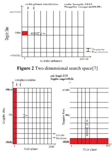
The Serial search algorithm searches for all the possible doppler bins and code phases sequentially as shown in figure-2. Here doppler bin is nothing but the frequency resolution, and code phase increment is the code phase resolution, both have values 500Hz and 0.5chip respectively.
From the figure-2 we can see that for our case Doppler range is of ±60kHz and PRN code length is 1023 chips. So for Serial search method total number of correlations required is equal to 2046x241.Hence it is a very tedious process, so we can think about parallelizing one of the two parameters.
From the figure-3 we can see that in left side window frequency parameter is parallelized so it is known as parallel frequency space based acquisition, and in right side window code phase is parallelized so it is parallel code space based search. For parallel frequency space based acquisition total number of correlation required is 2046x1, whereas for parallel code phase based acquisition it is 1x241. So parallel code phase space based acquisition is most time efficient approach. Here in the figure-3 code-phase resolution is 0.5 chip for explanation only, In implementation better code phase resolution 1/15 chip is used, which will stabilized the code tracking loop.
Let’s go through the theory to know how we can parallelize the code phase. This technique is based on circular correlation of Fourier transform.
Where x(n): received signal c(n): PRN code in time domain.
As we know that the equation-1 is nothing but the circular correlation of two sequences x(n) and c(n), so according to correlation property of Fourier transform property we can write that
Y(k) = X(k)C*(k) or Y(k) = X*(k)C(k) (2)
Where X(k) = DFT of x(n) C(k) = DFT of c(n)
From this we can say that Y(k) is nothing but the PSD(Power spectral density), which is simple multiplication of FFT of one signal with the complex conjugate of FFT of other signal. And by taking IFFT(inverse fast Fourier transform) of this PSD we can find the correlation in time domain, which will give us peak at code phase which is completely aligned
Figure 2 Two dimensional search space[7]
International Journal of Current Advanced Research Vol 5, Issue 3, pp 643-648, March 2016
with incoming signal’scode phase. So this approach searches for all the code phases simultaneously. Figure-4 shown below gives the idea about implementation of parallel code phase space based acquisition algorithm.
From the figure-4 we can see that incoming digitized IF signal is multiplied with locally generated carriers to generate in-phase and phase-quadrature components. Then after these components are given to FFT module, at the same time the locally generated code’s FFT will be complex conjugated. Then by taking complex multiplication of FFT of incoming signal with the complex conjugated FFT of code replica we find the PSD, and then by taking IFFT followed by magnitude will give us correlation of incoming signal and code replica. This correlation amplitude will be compared with threshold value to detect the signal is present or not.
Factors Affecting Acquisition process
There are mainly two factors that affects the acquisition process: C/No of incoming signal and Data processing time.
C/No of incoming signal
After searching the whole “search window” we will have to decide whether signal is present or not. For that we would have to decide the threshold, which will decide whether the noise present or signal+noise is present [6].
Whereσ =RMS noise amplitude = probability of false alarm.
As we know that for higher C/No Pd (probability of detection) is almost equal to 1.But as C/No decreases it depends on as shown in figure-5.
Here we are working on 40dBHz C/No so we will find the appropriate value of that will give the Pd as high as possible. Form the figure-5 we can say that if we set the =0.1 then the Pd=0.97, so it is the best option that suits to our application.
And the σ isthe RMS noise amplitudewhich can be find out by correlation of the incoming signal with the unused PRN code which is from the same family which we are using for our main PRN code.
Data processing time
Data processing time is also an impact factor that affects the Acquisition process, because acquisition time is directly proportional to integration (data processing) time. Since frequency resolution is mostly given by. So if the integration time is 1ms, then frequency resolution will be 500Hz, and if integration time increases then frequency resolution will decrease.
But longer integration time also improves the performance in lowerC/No, this we can know by below equation
Where C/N=carrier to noise ratio C/No=carrier to noise density ratio T=integration time.
So there is a trade-off between these two points, So integration time should neither be too long nor be too short [8]. This paper presents that acquisition can be performed up to 40dBHz by integration time of 2ms which is neither too long nor too short.
TRACKING
The acquisition module discussed above gives the coarse values of carrier Doppler shift and PRN code offset. These values will be handed over to the Tracking module, to precisely trace the carrier Doppler shift and code offset for fine tuning (precise synchronization). As a consequence there are two loops: a carrier loop trace the carrier and code loop for code tracing, and both runs simultaneously. For carrier loop FLL switched to PLL and for code loop DLL is used here.
To track the incoming CDMA signal, both the carrier phase and PRN code must be matched with the locally generated counterparts. As a consequence carrier lock loop (FLL switched to PLL) and Delay locked loop are combined together as shown in figure-6. Hence, if one of them loss the Figure 4 Parallel code phase space based acquisition [1]
Figure 5 ROC (receiver operating characteristics) curves
For different Pfa’s
lock, other will also loss the lock. The basic theory of tracking loop has been extencively explained by many researchers, So this part is skipped over here. Only the Discriminators used in implementation are summerized and then the loop designing is described.
PLL Discriminator
The four quadrant linear phase discriminator ATAN2, having ability to track the phase error in the range of ±180º is used here, to track the phase error. It gives the optimum result for carrier phase tracking irrespective of SNR (signal to noise ratio) either High or Low [6].
Though the PLL is more sensitive to dynamic stresses, and giving the accurate phase error in high dynamic, the robust wideband FLL is first choice of CDMA receiver designer, because it’s wider pull in range gives the tracked output faster.
FLL Discriminator
As PLL discriminator estimates the phase error, FLL discriminator estimates the frequency error. It is also referred to as AFC (Automatic frequency control) loop, because it replicates the approximate frequency, which is used for carrier wipe-off [6]. The FLL discriminator can be given by:
DLL Discriminator
Code dynamics are overshadowed by carrier dynamics because carrier frequency is approximately 2200 times higher than the code frequency. To find the code frequency error DLL discriminator is used [6].
FLL switched to PLL
In the above subsections code discriminator (DLL) and carrier discriminators (PLL and FLL) are briefly explained. But the paper focuses on FLL switched to PLL carrier tracking method .The switching mechanism is performed by Frequency lock detector, which is detect if the locally generated carrier frequency is successfully locked or not. Frequency lock detaector can be written as [5]:
Assuming, no external disturbance, this equals to the detector.
Ideally, an FLL detector locked around 0.95, wouldguarantee a frequency error less than noise bandwidth of FLLloop. However the lock detector output is noisy and cannot be reliably used in the receiver. To remove the noise, it will be passed through the simple moving average type of LPF (lowpass filter), and this filtered output will be compared with DET (detector).
Figure-7 and figure-8 gives the idea about how the Frequency lock detectorbehave before averaging and after averaging respectively.
Loop design
Filter is mainly used to reduce the effect of unintentional (noise) signal from the information bearing signal [7]. Loop filter here also performs same operation, Here our information bearing signal is nothing but the carrier phase/frequency error and code phase error signals. Consequently, Loop filter reduces the effect of noise and produces the accurate output which will be fed back to the carrier and code generators as shown in Combined Tracking loop block diagram. In the
block diagrams, the loop filter’s output signal is subtracted
from the original signal to produce an error signal, which is
fed back into the filter’s input in a closed loop process. Loop filter’s order and it’s noise bandwidth determine the loop filter’s response to signal dynamics.
Second Order loop
For the second order tracking loop, filter transfer function will have the order equals to unity. So general form of filter will be as below [6]:
Figure 7 noisy lock detector
Figure 8 filtered lock detector lock, other will also loss the lock. The basic theory of
tracking loop has been extencively explained by many researchers, So this part is skipped over here. Only the Discriminators used in implementation are summerized and then the loop designing is described.
PLL Discriminator
The four quadrant linear phase discriminator ATAN2, having ability to track the phase error in the range of ±180º is used here, to track the phase error. It gives the optimum result for carrier phase tracking irrespective of SNR (signal to noise ratio) either High or Low [6].
Though the PLL is more sensitive to dynamic stresses, and giving the accurate phase error in high dynamic, the robust wideband FLL is first choice of CDMA receiver designer, because it’s wider pull in range gives the tracked output faster.
FLL Discriminator
As PLL discriminator estimates the phase error, FLL discriminator estimates the frequency error. It is also referred to as AFC (Automatic frequency control) loop, because it replicates the approximate frequency, which is used for carrier wipe-off [6]. The FLL discriminator can be given by:
DLL Discriminator
Code dynamics are overshadowed by carrier dynamics because carrier frequency is approximately 2200 times higher than the code frequency. To find the code frequency error DLL discriminator is used [6].
FLL switched to PLL
In the above subsections code discriminator (DLL) and carrier discriminators (PLL and FLL) are briefly explained. But the paper focuses on FLL switched to PLL carrier tracking method .The switching mechanism is performed by Frequency lock detector, which is detect if the locally generated carrier frequency is successfully locked or not. Frequency lock detaector can be written as [5]:
Assuming, no external disturbance, this equals to the detector.
Ideally, an FLL detector locked around 0.95, wouldguarantee a frequency error less than noise bandwidth of FLLloop. However the lock detector output is noisy and cannot be reliably used in the receiver. To remove the noise, it will be passed through the simple moving average type of LPF (lowpass filter), and this filtered output will be compared with DET (detector).
Figure-7 and figure-8 gives the idea about how the Frequency lock detectorbehave before averaging and after averaging respectively.
Loop design
Filter is mainly used to reduce the effect of unintentional (noise) signal from the information bearing signal [7]. Loop filter here also performs same operation, Here our information bearing signal is nothing but the carrier phase/frequency error and code phase error signals. Consequently, Loop filter reduces the effect of noise and produces the accurate output which will be fed back to the carrier and code generators as shown in Combined Tracking loop block diagram. In the
block diagrams, the loop filter’s output signal is subtracted
from the original signal to produce an error signal, which is
fed back into the filter’s input in a closed loop process. Loop filter’s order and it’s noise bandwidth determine the loop filter’s response to signal dynamics.
Second Order loop
For the second order tracking loop, filter transfer function will have the order equals to unity. So general form of filter will be as below [6]:
Figure 7 noisy lock detector
International Journal of Current Advanced Research Vol 5, Issue 3, pp 643-648, March 2016
Where assume that Y(z): filter output, X(z): filter input So output of the filter in time domain can be given by
Third order loop
For the third order loop the filter transfer function will be of second order as below [6],
These parameter defines the noise bandwidth of the loop filter, and it will be Bn equals to 0.7874 By using above equations we can design 3rdorder PLL loop filter.
Simulation Results
We have implemented the proposed algorithm for the CDMA signal having S-band frequency 2.2GHz, which is down converted to Intermediate frequency 3.75MHz and then sampled at the frequency 15 MHz, Code rate is of 1Mcps.
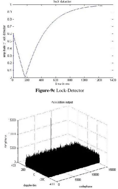
Figure-9a without noise and for lower doppler acquisition output:
Acquired doppler = 0Hz
Figure-9b without noise and lower doppler tracking loop outputs
Figure-9c Lock-Detector
Figure 10a 40dBHz noise and Higher doppler acquisition output:
Here in the figure-9a,9b and 9c, Acquisition module output, Tracking module outputs and FLL loop lock detector output are shown respectively. And the case considered for that is without noise 225Hz doppler, we can see in the figure-9a that correlation peak is in doppler bin 0, means acquired doppler frequency is 0 Hz, so tracking loop will trace the frequency up to -211Hz because FLL loop gives the negative frequency difference, and further frequency is tracked by PLL as shown in figure 9b it will stable around 15Hz.FLL switched to PLL when lock detector output is above 0.96 as we can see in figure 9c.Lock detector starts after 10 iterations and stop when exceed 0.96.The reason of starting after 10 iterations is that, actual lock detector output is passed through the moving average type of LPF, and here moving average is considered for 10 samples.
In the figure 10a,10b and 10c, the acquisition and tracking loop and lock detector outputs are shown for 40dBHz C/No and 59345Hz doppler. We can find the difference in Figure 9a and Figure 10a by simply examine it, that Doppler bin resolution are different, it is just because for lower C/No we should have to perform correlation for longer duration (Integration time).
Tracking loop for this case similarly works as in the first case, so it will track up to -87Hz by FLL and further 8Hz by PLL, as the acquired doppler frequency is 59250Hz.
CONCLUSION AND FUTURE SCOPE
Above proposed algorithms are designed to work well in high dynamic scenario with Doppler range up to 60kHz, Doppler rate of ±66Hz/s, and low C/No (40 dB-Hz).
This work can be useful in inter-satellite communication link (between GEO (Geo-stationary orbit) and LEO (Low Earth Orbit) satellites), where low data rate TTC operation is carried out. TT&C operations of LEO satellites can be carried out by GEO satellite. This design can be fit into the receivers at GEO or LEO satellites.
Acknowledgment
The authors thank all the reviewers for giving critical comments and suggestions for improving the quality of the paper. The authors like to express their gratitude towards the Satellite Navigation Systems Engineering Division and the management of SAC, ISRO Ahmedabad for their support and encouragement during this work. Authors also like to express their thanks to the Department of Electronics and Communication, L. D. college of Engineering Ahmedabad.
References
1. QIU LIE and Li LIE, “GPS Signal Acquisition based on FFT”, second international Conference on Information Technology and Computer Science, IEEE 2010.
2. M. VenuGopala Rao and D. Venkata Ratnam, “Faster Acquisition Technique for Software-defined GPS Receivers”,Defense Science Journal, January 2015. 3. Nomi Sonowal, Rajjev Yadav and S. Kannan, “Real
Time GPS Software Reciever with New Fast Signal Tracking Method”,IEEE 2008.
4. C.Mongredien, G.Lachapelle and M.E.Canon, “Testing GPS L5Acquisition and Tracking Algorithms using Hardware Simulator”, ION GNSS 2006, Fort Worth TX, September 2006.
5. Cristian E. DeBlassis and Carlos H. Muravchik, Pedro A. Roncagliolo, “GPS Digital Tracking Loops Design for High Dynamic Vehicle Launching”, IEEE Ninth International Symposium on spread spectrum Techniques and application 2006.
6. Kaplan E D. Understanding GPS principles and applications, USA: Artech House, 1996.
7. James Bao-Yan Tsui, Fundamentals of Global Positioning System Receivers - A Software approach, John Wiley & Sons, Inc., Hoboken, NJ, 2005.
Figure 10b40dBHz noise and Higher doppler Tracking loop
outputs
Figure 10c Lock Detector

![Figure 4 Parallel code phase space based acquisition [1]](https://thumb-us.123doks.com/thumbv2/123dok_us/1359469.1645037/3.595.341.527.527.712/figure-parallel-code-phase-space-based-acquisition.webp)