9
Design and Implementation of Adaptive PID
based UAV Shaft Position Control
1
Jagroop Singh,
2Poonam Kumari,
3H.P.S.Kang
1,2,3UCIM Panjab University, Chandigarh, UT, India
Abstract
PID controllers have played a great role in industry for controlling different plants with accuracy. Also, various PID control algorithms have been framed to ease its implementation and improve the response of the system. However, conventional manual tuning methods have faced the problems of lesser precision and higher response time. Various automatic PID tuning methods have been designed to solve this control problem. Adaptive tuned PID is one of the most widely applicable techniques in controlling a plant output automatically to the desired set point with more accuracy and precision. This research is focused on designing a laboratory scale model for PID and Adaptive tuned PID controller for UAV shaft position control. The output is generated on the LabVIEW software and various transient response characteristics of the designed laboratory model are depicted in the results.
Keywords
PID; Unmanned Aerial Vehicles; brushless motor; transient characteristics.
I. Introduction
PID controllers are found in a wide range of applications for industrial process control. Approximately 95% of the closed loop operations of industrial automation sector use PID controllers [1]. PID stands for Proportional-Integral-Derivative. These three controllers are combined in such a way that it produces a control signal. Proportional-Integral-Derivative (PID) control is the most common control algorithm used in industry and has been universally accepted in industrial control [2-3]. The popularity of PID controllers can be attributed partly to their robust performance in a wide range of operating conditions and partly to their functional simplicity, which allows engineers to operate them in a simple, straight forward manner. The PID controller
is applied in various fields of engineering, and it is also a very
important tool in telecommunication system. If there is a system and stability is desired, then PID could be very useful. In practice, the design of the BLDCM drive involves a complex process such as modeling, control scheme selection, simulation and parameters tuning etc [4]. The basic idea behind a PID controller is to read a sensor, then compute the desired actuator output by calculating proportional, integral, and derivative responses and summing those three components to compute the output [5]. As the name suggests,
PID algorithm consists of three basic coefficients; proportional,
integral and derivative which are varied to get optimal response [6]. The adaptive control is used for the automatic adjustment in real time of the process parameters [7]. The synthesis of an adaptive controller is done based upon the following parameters:
Based upon the required performance specification of the •
control system.
Based upon the type of the control structure required to meet
•
the desired performance specifications.
Based upon the mechanism to be adopted for the adaptive
•
parameter setting of the controller and setting the optimum values.
The interest of the adaptive control appears essentially in the level of the parametric disruptions, that is, acting on the characteristics of the process to control. The dynamic model of the plant can be recognized from input/output plant dimensions obtained under an experimental etiquette in open or in closed loop [8-9]. One can say that the design and tuning of the controller is done from data collected on the system. An adaptive control system can be viewed as an apprehension of the design and tuning procedure in
real time [10]. The tuning of the controller will be finished in real
time from data collected in real time on the system
Fig. 1: An Adaptive Control System [10]
II. Unmanned Aerial Vehicles
An unmanned Aerial Vehicle (UAV), commonly known as a drone, is an aircraft without a human pilot aboard. UAVs are a component of an unmanned aircraft system (UAS); which include a UAV, a ground-based controller, and a system of communications
between the two [11-12]. The flight of UAVs may operate with
Fig. 2: Unmanned Aerial Vehicle for Surveillance Applications
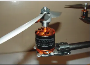
The motor employed in most of the UAV’s are brushless motors. Brushless dc electric motor (BLDC motors, BL motors) also known as electronically commutated motors (ECMs, EC motors) are synchronous motors powered by dc electricity via an inverter/ switching power supply which produces an ac/bi-directional electric current to drive each phase of the motor via a closed loop controller [15].
Fig. 2: Brushless Motor with Propeller Mounted on the Shaft of a UAV
Brushless motors are usually mounted on the shaft of the UAV and control the height and direction of motion of the UAV. The speed and direction of the brushless motor is usually controlled by an electronic speed controller [16]. This circuit is compact and contains a microcontroller that sends the PWM signal to the input of the brushless motor based upon feedback from various sensors. An electronic speed control or ESC is an electronic circuit that controls and regulates the speed of an electric motor [17]. It may also provide reversing of the motor and dynamic braking. Miniature electronic speed controls are used in electrically powered radio controlled models. Full-size electric vehicles also have systems to control the speed of their drive motors.
III. Objective
The objective of proposed work is to design hardware using components used in aerial vehicle having a PID control system with different tuning methods, i.e., manual tuning and adaptive tuning algorithms. The aim of the project is to implement these two controllers for a UAV shaft balancing system depicted with the help of a brushless motor mounted with a propeller on wooden shaft placed in the stand. The speed of the motor is controlled with the designed algorithms in real time and obtain the transient response on a LabVIEW Virtual Instrument. The speed of the motor determines the position of the UAV shaft by varying the angle of the shaft. The programming involves an Arduino Uno microcontroller to be used as the data acquisition device with the
LabVIEW to get the desired inputs from the hardware and pass it on to the VI using serial communication and also to get the data from the VI to control the hardware position and angle. Following objectives are to be achieved by the proposed design.
To develop a simulator for real time position control of a
•
UAV shaft by using PID control.
To design the hardware for implementation of the UAV shaft
•
balancing system using brushless motor.
To develop a programming algorithm for accurate and stable
•
closed loop response for the system using microcontroller and LabVIEW.
To design an intelligent controller using PID control algorithm
•
and different tuning methods in real time.
To compare different tuning methods and generate the transient
•
response of the real time implementation in LabVIEW with PID and Adaptive PID control technique.
IV. Problem Formulation
The industry on which the proposed work may be carried out is an aerial vehicle. The Multicopters such as Quadcopter, Hexacopter etc. are frequently used in airborne application where hovering is required. In Multicopters due to number of motors an intelligent control algorithm is required to balance the thrust produced by all motor to achieve desired stability after taking feedback from accelerometer and gyroscope. However, in our project feedback in the proposed design is to be taken from a potentiometer in order to balance a shaft on which the motor is mounted. A brushless motor with propeller is to be considered for base motor whose speed control will eventually balance the shaft. The angle of the shaft that is the feedback parameter is to be considered for controlling the speed. This is performed by means of PID and Adaptive PID controller.
V. Design Methodology
The initial step is to control the position of the UAV with manual tuned PID. With enough information about the process being controlled, it may be possible to calculate optimal values of gain, reset and rate for the PID controller. Often the process is too complex, but with some knowledge, particularly about the speed with which it responds to error corrections, it is possible to achieve a rudimentary level of tuning. Manual PID tuning is done by setting the reset time to its maximum value and the rate to zero and increasing the gain until the loop oscillates at a constant amplitude. When the response to an error correction occurs quickly a larger gain can be used. If response is slow a relatively small gain is desirable. Then set the gain of the PID controller to half of that value and adjust the reset time so it corrects for any offset within an acceptable period. Finally, increase the rate of the PID loop until overshoot is minimized. Here, the process under control
is the UAV shaft control for maintaining the position, ‘θ’, i.e.
the angle of the shaft for attaining the perfect balancing and the speed of the brushless motor to be controlled. In this step, the PID algorithm was implemented in the controller with feeding the constant values for the proportional (Kp), integral (Ki) and derivative (Kd) constants in the algorithm. It also required frequent changes in the Kp, Ki and Kd values.
11
Fig. 3: Block Diagram of the Proposed Design
VI. Experimental Setup
The hardware implementation for the proposed model based on shaft balancing of the UAV using the PID control of a brushless motor mounted on the shaft is carried out using various material and components. A propeller is attached on the top of brushless motor to provide it thrust to lift upwards in order to control the system to achieve set point measured by a feedback potentiometer forming the closed loop system. This brushless motor is allowed to lift in either direction (up and down) based on the feedback taken from a potentiometer mounted on the middle of the shaft that generates an analog output voltage proportional to the angle of the shaft.
The idea is to keep the shaft maintain a particular height without
any fluctuations and transients in the motion. This is achieved by
the brushless motor speed control using the designed algorithm. A DAQ system using Arduino uno microcontroller is used to calibrate the controller and to provide the control signal to the hardware model. It also takes the data from the hardware based on present position and transfers it to the simulator design in the LabVIEW as the VI. Optimum parameters for the Kp, Kv and Ki are calculated by means of the programming in the controller with PID and Adaptive tuned PID controller and the resultant is obtained on the VI and also seen in the hardware by maintaining fairly stable position of the shaft.
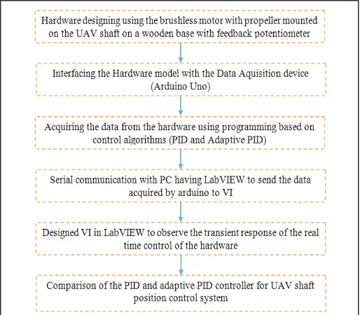
The algorithm used for the design and implementation of UAV
shaft position control is depicted in fig. 4.
Fig. 4: Algorithm Followed for Designing the UAV Shaft Position Control Using Adaptive PID Approach
The shaft is made of aluminum pipe that represents the single shaft of a UAV that is to be balanced. Also, at the end of the shaft, a brushless motor is mounted with the help of supporting clamps and a propeller. The electronic circuit of the UAV shaft position control
is depicted in the fig. 5. The mechanical framework consists of the aluminum shaft which fixed on a base and a stand with the help
of a counter load and a potentiometer is placed for the feedback at the end of the shaft. Further, the mounting of potentiometer is done with the help of hub for angle measurement in order to take the feedback. The design represents brushless motor that is mounted on one end of the shaft with a potentiometer at the center of the shaft for getting the values of the anlge and direction of the movement. The ESC is mounted in between the brushless motor and the potentiometer. On the other end of the shaft, a
counter weight is fixed that could be adjusted according to the
requirements. A propeller is attached on the top of brushless motor to provide it thrust to lift upwards in order to control the system to achieve set.The speed of the brushless motor is controlled using an miniature dc to AC 3 phase converter that further receives the PWM signal from a controller output. The controller used here is an Atmega 32 microcontroller embedded in an Arduino uno board.
Fig. 5: Electronic Circuit Diagram of the UAV Shaft Position Control Using Adaptive PID
VII. Result and Discussion
The software implementation was done using the LabVIEW
software and Arduino IDE. The data acquisition firmware was
developed in the Arduino IDE that is an open source software used for developing programs and compiling the same into the
Arduino firmware. LabVIEW is used to design the Simulator
of the control system of the UAV shaft position and the output parameters like transient response and values of Kp, Ki and Kd tuning parameters can be obtained from the Virtual Instrument designed in LabVIEW.
Fig. 6: Block Diagram of the LabVIEW VI Designed to View the Response of the Designed System
The Simulator was designed in the LabVIEW VI to see the results of the UAV shaft position control using PID and adaptive PID
algorithm that is configured in terms of the transient response. The
controllers were implemented in the programming done in arduino microcontroller and the PWM output was used to control the speed of the brushless motor and hence the position of the shaft. The results were acquired by designed Simulator in LabVIEW with the help of the designed DAQ system using arduino uno board and the hardware designed to control he shaft position of the UAV based on the PID tuning parameters. Following results
were obtained at various loads and fluctuations in the shaft angle.
The output response generally shows the measured PID variable, that is the desired angle and the set point that is set for the shaft using external potentiometer.
The transient response for manual tuned PID controller for UAV
shaft position control is depicted in fig. 7.
Fig. 7: Manual tuned PID Transient Response for UAV Shaft Position Control
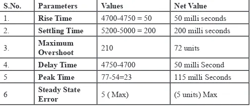
The results obtained for various parameters of the graph are depicted in Table 1.
Table 1: Results of Parameters for Transient Response of Manual Tuned PID for UAV Shaft Position Control
S.No. Parameters Values Net Value
1. Rise Time 4700-4750 = 50 50 milli seconds 2. Settling Time 5200-5000 = 200 200 milli seconds 3. Maximum Overshoot 210 72 units 4. Delay Time 4750-4700 50 milli Second 5 Peak Time 77-54=23 115 milli Seconds 6 Steady State Error 5 ( Max) (5 units) Max
From the above graph of transients response of Manual PID tuned at particular value of Kp= 0.62, Ki= 3343.1, Kd= 3.9 is having a decaying oscillation with underdamped Response.
In adaptive PID controller we two type of tuning parameter one is call Aggressive parameter and other is call conservative parameter. We set the adaptive controller to use the conservative parameter when controller is near the set-point and more aggressive Tuning parameter when we are farther away from the set-point. Since in adaptive PID algorithm there are two set of Tuning parameter, so a different LabVIEW application for recording the real time analysis of variation of set-point with respect to output.
The transient response for adaptive tuned PID controller for UAV
shaft position control is depicted in fig. 8.
Time
Fig. 8: Adaptive Tuned PID Transient Response for UAV Shaft Position Control
The results obtained for various parameters of the graph are depicted in Table 2.
Table 2: Results of Parameters for Transient Response of Adaptive Tuned PID for UAV Shaft Position Control
S.No. Parameters Values Net Value
1. Rise Time 400-440=40 40 milli seconds 2. Settling Time 500-430=24 70 milli seconds 3. Maximum Overshoot 10 10 Units 4. Delay Time 430-380 5 milli Second 5 Peak Time 440-380 60 milli Seconds 6 Steady State Error 2 unit ( Max) 2 units
From above transient response it is clear that system having underdamped response having damping ratio <1
VIII. Conclusion
From the results obtained by software simulation and hardware implementation of Adaptive and manual tuned PID controller, it can be concluded that the response time parameters steady state error for adaptive tuned PID such as is slightly less that manual tuned PID controller, settling time of Adaptive PID controller is far better or Less than Manual PID Controller however, the response parameters like steady state error and maximum
overshoot have been reduced significantly along with improved
13
References
[1] M. Kamran Joyo, S. Faiz Ahmed, D. Hazry, M. Hassan Tanveer, Faizan. A. Warsi,“Position Controller Design for Quad-rotor under Perturbed Condition”, Wulfenia Journal, Austria, Vol. 20, No. 7, 2013.
[2] C´eline Teuli`ere, Laurent Eck, Eric Marchand, Nicolas Gu´enard, 3D model-based tracking for UAV position control, Intelligent Robots and Systems (IROS), IEEE Xplore, Vol. 10, Oct, 2010.
[3] I.D.Landau,"A Survey of Model Reference Adaptive Techniques-Theory and Applications”, Automatica, Vol. 10, pp. 353-379, pergamon press, 1974, Printed in Great Britain.
[4] Patrick Adigbli,“Nonlinear Attitude and Position Control of a Micro Quadrotor using Sliding Mode and Backstepping Techniques”, 3rd US-European Competition and Workshop on Micro Air Vehicle Systems (MAV07) & European Micro Air Vehicle Conference and Flight Competition (EMAV2007), 17-21 September 2007.
[5] Kalpesh B. Pathak, Dipak M. Adhyaru (Member,IEEE),“Survey of Model Reference Adaptive Control”, NUiCone- 012, Nirma University International Conference of Engineering, pp. 1-6, 06-08 December, 2012
[6] Vinod KR Singh Patel, A.K.Pandey,“Modelling and Performance Analysis of PID controlled BLDC Motor and Different Schemes of PWM Controlled BLDC Motor”,
International Journal of Scientific and Research Publications,
Vol. 3, Issue 4, pp. 1-14, 2013.
[7] Michel Van Dessel,“Control of an Industrial Process Using PID Control blocks in AutomationController”, pp. 1-9, 2012.
[8] Jae Kawn Lee, Bo-Hyeok-Suh, Ken-Ichi Abe,“Model Reference Adaptive Control of Nonlinear System using Feedback Linearization”, SICE ‘95. Proceedings of the 34th SICE Annual Conference. International Session Papers, Hokkaido, pp. 1571-1576, 26-28 July 1995.
[9] Cervin, Henriksason, Lincoln, Eker, Arzen,“Analysis And Simulation of Timing Using Jitterbug and TrueTime”, IEEE Control System Magazine, pp 16-30, 2003.
[10] Hengameh Noshahri, Hamed Kharrati,“PID controller design for unmanned aerial vehicle using genetic algorithm”, IEEE International symposium on Industrial Electronics, Vol. 2, Issue 1, pp. 213 - 217, 2014.
[11] Zefang He, Long Zhao,“Quadrotor trajectory tracking based on internal model control/ZN-PD control”, Control Conference (CCC) 2016 35th Chinese, pp. 945-950, 2016. [12] K. Niki Maleki, Kaveh Ashenayi, Loyd R Hook, Justin
G Fuller, Nathan Hutchins,“A reliable system design for nondeterministic adaptive controllers in small UAV autopilots”, Digital Avionics Systems Conference (DASC) 2016 IEEE/AIAA 35th, pp. 1-5, 2016.
[13] Hans Petter Halvorsen,“Data Acquisition in LabVIEW”, Tutorial, Telemark University College, Department of Electrical Engineering, Information Technology and Cybernatics, Norvey, August 2013.
[14] S.J.Chriswright Johnsingh, R.Jagan Vignesh, B.Chinthamani, “Lab VIEW Based Process Control and Monitoring For Industrial Process Parameters”, International Journal of Advanced Research in Electrical, Electronics and Instrumentation Engineering Vol. 3, Special Issue 2, pp. 112-117, 2014.
[15] P D Shendge, Prasheel V Suryawanshi, B M Patre,“Robust Sliding Mode Control for Systems with Noise and Unmodeled Dynamics Based on Uncertainty and Disturbance Estimation (UDE)”, International Journal of Computer Applications Vol. 1 , Issuse 9, pp. 37–42, 2010.
[16] Astrom KJ, Hagglund T.,“The Future of PID Control”, Control Engineering, Practice, Elsevier, Vol. 9, Issuse 11, pp. 1163–75, November 2001.
[17] Ang KH, Chong G, Li Y.,“PID Control System Analysis, Design, And Technology”. IEEE Transactions on Control Systems Technology, Vol. 13, Issuse 4, pp. 559–76, 2005. [18] R. Prakash, R. Anita,“A New Approach to Model Reference
Adaptive Control Using Fuzzy Logic Controller for Nonlinear Systems”, International Journal of Computer Science and Information Security, Vol. 9, pp. 86–96, 2011.
[19] F. Mrad, G. Deeb,“Experimental Comparative Analysis of Adaptive Fuzzy Controllers”, IEEE Transactions on Control Systems Technology, Vol. 10, No. 2, 2002.
[20] Mamdani EH.,"Applications of fuzzy algorithms for simple dynamic plant", ProcIEE;121(12), pp 1585–8, 1974. [21] Palm R. Sliding mode fuzzy control. In: Proc fuzz IEEE,
San Diego, CA, pp 519–26, 1992.
[22] Savran A, Kahraman G.,“A Fuzzy Model Based Adaptive PID Controller Design for Nonlinear and Uncertain Processes”. ISA Trans, Elsevier, Vol 53, Issuse 2, pp. 280–288, 2014. [23] Mohammad El-Bardini M, El-Nagar AM.,“Interval Type-2
Fuzzy PID Controller for Uncertain Nonlinear Inverted Pendulum SystemISA Trans,Elsevier, Vol 53, Issuse 3, pp. 732–743, 2014.
[24] Premkumar K, Manikandan BV.,“Adaptive Neuro-Fuzzy Inference System Based Speed Controller for Brushless DC motor”. Neurocomputing, Vol. 138, pp. 260–70, 2014. [25] Wang PP, Tyan C.,"Fuzzy Dynamic Systems and Fuzzy
Linguistic Controller classification", Automatica, Vol. 30,
Issuse 11, pp 1769–1774, 1994.
[26] Li HX, Gatland HB.,"Conventional Fuzzy Control and its Enhancement", IEEE Trans Syst Man Cybern,Vol. 26, Issuse 5, pp. 791–797, 1996.
[27] Lee J.,“On methods for improving performance of PI-type Fuzzy Logic Controllers”, IEEE Transaction Fuzzy System, Vol. 1, pp. 298–301, 1993.
[28] Tadej TAŠNER, Darko LOVREC, Francisek TASNER, Jorg EDLER,“Comparison of LabVIEW and MATLAB
For Scientific Research”, Analysis of Faculty Engineering
Hunedoara-International Journal of Engineering Tome X- Fascicule 3, 2012.
[29] I.D.Landau, Roeilio Loanzo, Mohammad M’Saad, Alireza Karimi, "Adaptive Control, Algorithm, Analysis and Applications, Second Edition, Springer Science And Bussiness Media.
![Fig. 1: An Adaptive Control System [10]](https://thumb-us.123doks.com/thumbv2/123dok_us/1335824.1642080/1.595.304.561.284.439/fig-an-adaptive-control-system.webp)