e-ISSN: 2278-067X, p-ISSN: 2278-800X, www.ijerd.com
Volume 11, Issue 03 (March 2015), PP.57-62
Enhancement of Power Quality Using the Combination of
Thyristor-Controlled Reactor and Shunt Active Filter
P.Vimala
1, S.Asok kumar
2, T.Illansezhian3, S.Jeevitha
41Associate Professor, IFET College of Engineering, Villupuram. 2
Assistan Professor, IFET College of Engineering, Villupuram 3
Sr.Assistant Professor, IFET College of Engineering, Villupuram 4UG Scholar, IFET College of Engineering, Villupuram
Abstract:- This paper proposes the combined system of a thyristor – controlled reactor (TCR) and the shunt active filter for harmonic and reactive power compensation. The tuned passive filter and the TCR form a shunt passive filter to compensate the reactive power. The power system harmonics are a menace to electric power system with disastrous consequences. The line current harmonics can cause increase in losses, instability and voltage distortion. Shunt active filters have been used near harmonic producing loads or at the point of common coupling to block the current harmonics. With the diverse application involving reactive power together with harmonic compensation, passive filters are found suitable. The total harmonic distortion and compensation current are carried out in MATLAB using SIMULINK. With the increase in non-linear loads in power system, more and more filters are required. The active filters are designed and analysed to improve the power quality
Keywords:- TCR , shunt active filter, Total harmonic distortion, power quality, power quality.
I.
INTRODUCTION
The supply current is distorted by the non-linear loads such as UPS, DC drives, AC drives and arc furnace etc. The growing use of non-linear and time varying loads has lead to distortion of voltage and the current wave forms and increased in reactive power demand in AC mains. Harmonic distortion is known to be source of several problems such as increased power losses, excessive heating of rotating machines, audible noise and incorrect operation of sensitive loads etc. Nowadays shunt active power filter based on the voltage source inverter is used because of its efficiency. Similarly, the thyristor-controlled reactor is used to compensate the reactive power flows in the transmission line. The Synchronous Resonance Theory and dq Transformation Theory are used to generate the fundamental components of the supply current.
II.
THYRISTOR-CONTROLLED
REACTOR
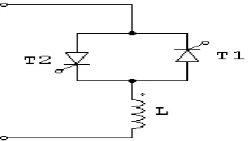
A linear air - cored reactor is connected in series with the anti-parallel connected thyristors is known as TCR. The TCR goal is to obtain the regulation of reactive power. The anti-parallel connected thyristor pair acts like a bidirectional switch,with the thyristor valveT1 conducting in positive half cycles and the thyristor valve T2 conducting during the negative half cycle. A firing angle of 90` is results in full thyristor conduction mode. Once the thyristor valves are fired the cessation of current occurs at its natural zero crossing , a process is known as line commutation.
The TCR thus acts like a variable susceptance. Variations of firing angle will changes the susceptance and consequently ,the fundamental current component which leads to the variation of the reactive power absorbed by the reactor because the supply voltage remains constant.
A. Shunt Active Filter
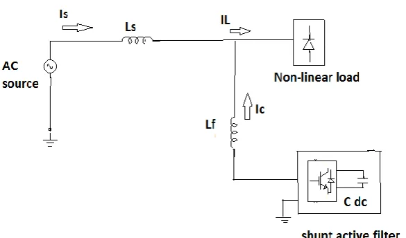
The active power filter consists of a three-phase full-bridge voltage -source pulse width modulation (PWM) inverter with an input boost inductor and a dc bus capacitor (Cdc). The APF sustains very low fundamental voltage and currents of a power grid, and thus, its rated capacity is greatly reduced. Because of these merits, the presented combined topology is very appropriate in compensating reactive power and eliminating harmonic currents in power system. The tuned passive filter in parallel with TCR forms a shunt passive filter (SPF). This latter is mainly for fifth-harmonic compensation and PF correction. The small-rating APF is used to filter harmonics generated by the load and the TCR by enhancing the compensation characteristics of the SPF aside from eliminating the risk of resonance between the gird and the SPF .
III.
WORKING
The shunt active power filter will compensate the current harmonics by injecting the equal and opposite phase compensating harmonic current. In this case shunt active filter will acts as current source injecting the harmonic component generated by the load but phase shifted by 180` . this principle is applicable to any type of load consider as harmonic source. Moreover with appropriate control scheme,the active power filter will also compensate the load power factor. In this way the power distribution system sees the non-linear load and active power filter as a ideal resistor.
Fig. 2: Shunt Active Power Filter Configuration
A. Non-Linear Loads
The three phase diode rectifier with parallel resistor load is used as non-linear load which distorts the supply currentand genearate the harmonics. The supply current contains the fundamental component and harmonic component. It is also consumes the reactive power from the supply line. Examples of Non-linear loads are computer system, arc furnance,UPS, AC drives, DC drives etc.
B. Mathematical Analysis
The combination of thyristor – controlled reactor and shunt active filter is used for compensating the reactive power and reducing the harmonic current of the supply line which is genarated by the Non-linear loads. The supply voltage is sinusoidal form but the supply current is non-sinusoidal form due the connection of Non-linear loads in the supply line.
The supply voltage is given by ,
V
s
V
msin(
1t
)
(1)
Due to the Non-linear loads,the supply current contains the fundamental components and harmonic component,
1 1
( )
sin(
)
L k k
k
i t
I
k t
1 1 1 1 2
( ) sin( ) sin( )
L k k
k
i t I
t
I k
t
(3)Where
I1 = fundamental current
Ik = k th
harmonic current Vm = maximum supply voltage
Φk = phase angle between the supply voltage and current of the kth harmonic component.
The load current is given by ,
( )
( )
( )
L f h
i t
i t
i t
(4) For harmonic compensation and reactive power compensation, the supply currrent should have the fundamental component and it should be in phase with supply voltage.
The supply current is given by ,
1 1
( )
sin(
)
( )
s f f
I t
I
k
t
i t
(5) The harmonic current can be given as ,
i t
h( )
i
af( )
t
i
pf( )
t
(6)The load current is given as
i t
L( )
i
af( )
t
i
pf( )
t
i t
s( )
(7)Where iaf(t) = active filter current.
The equation (3) can be expressed as
1 1 1
( )
sin(
) *cos
L r d hr
i t
I
t
I
I
I
(8) Where
1 1
cos(
1) sin
1r
I
I
t
(9)1 2
sin(
) for k
d
hr k k
k
I
I
k t
(10)1
sin(
)
d pf dm d
I
i
I
d
t
The filter current is given by
i
af
I
r1
I
hr(11)
Where Ir1 = fundamental reactive current component and Id = dominant harmonic current
d = dominant harmonic order and Ihr = remaining harmonic component of the supply current
Φ = phase angle between corresponding current and supply voltage.
The zpf is the resonant filter tuned for the dominant frequency,so that it will inject the I pf to the supply
mains. The shunt active filter will inject the Ihr and the Ir1 current so that the supply is free from the harmonics
and the power factor is near to unity.
c. dq Transformation Theory :
The dq theory is based upon the time domain reference signal estimation technique. The dq components istd,istq are filtered by Bessels filter.
Direct Axis Frame :
istd = 0.67( ista sin(ω1t) – istb sin(ω1t - 2π/3) + istc sin(ω1t + 2π/3)) (12)
Quatrature Axis Frame
istq = 0.67( ista cos(ω1t) – istb cos(ω1t - 2π/3) + istc cos(ω1t + 2π/3)) (13)
This filter will filter the ripple content of dq component and it will be tranformed into a-b-c coordinates to obtain the fundamental component of the supply current.
Ira = id sin(ω1t) + iq cos(ω1t) (14)
Irb = id sin(ω1t - 2π/3) + iq cos(ω1t - 2π/3) (15)
Irc = id sin(ω1t + 2π/3) + iq cos(ω1t + 2π/3) (16)
Where Ira, Irb, Irc are the reference currents and ista, istb, istc are the three phase supply current.
IV.
HYSTERESIS CONTROLLER
The hysteresis controlling technique is used to generate pulse to the shunt active filter which exracts the harmonic component of the same magnitude and opposite in phase with the load current. The three phase voltage source inverter is used as active filter and IGBT switches are used in the inverter circuit for thye purpose of turn ON and turn OFF. The switching function ck of the kth leg of the converter (for k = 1, 2, 3) is defined as
ck=1, if Sk is On and S’kis Off
V.
RESULTS AND DISCUSSION
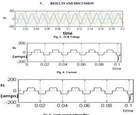
Fig. 3: TCR Voltage
Fig. 4: Current
Fig. 5: supply current without filter:
Fig. 6: supply current without filter
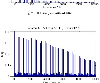
Fig. 7: THD Analysis- Without Filter
Fig. 8: THD Analysis- With Filter
The thyristor-controlled reactor and shunt active filter are simulated in MATLAB using power system blockset. The THD analysis before compensation is 30.26% . but after the compensation, the THD range is 4.01%. thus ,the reduction in the harmonics presented in the current is achieved using the combination of thyristor-controlled reactor and shunt active filter.
VI.
CONCLUSION
In this paper, the combination of thyristor-controlled reactor and shunt active filter has been proposed in order to achieve the harmonic elimination and reactive power compensation. The waveforms and THD analysis are done using MATLAB simulink shows the reduction in supply current harmonics and compensation of reactive power flow in the transmission line. Thus, the Hysteresis controlled shunt active filter is used to improve the performance.
ACKNOWLEDGEMENT
I wish to thank my parents for their undivided support and interest who inspired me and encouraged me to go my own way, without whom I would be unable to complete my journal. At last but not the least I want to thank my friends who appreciated me for my work and motivated me and finally to God who made all the things possible.
REFERENCES
[1]. M.Augalo, S.A.Mussa “Active power filter control strategy with implicit closed loop control and resonant controller”,IEEE Trans.Ind.,electron, july 2013.
[2]. Sivaranjani.R and jayalalitha .S “ Harmonics and reactive power compensation using the shunt active filters” International conference on recent advancement in Electrical and Electronics control, 2013 [3]. Sivaranjani.R and jayalalitha .S “Improvement of DC bus voltage of shunt active filterusing the
controllers”, International conference on recent advancement in Electrical and Electronics control, 2011.
[4]. Poorvi.M and prof.M.V.Makawana “ Harmonics analysis using the shunt active filters” in Journal of information , knowledge and research in Electrical Engineering,2011.
[5]. A.Hamadi and S.Rahmani “ A hybirdpassive filter configuration for VAR control and harmonics compensation” ,IEEE Trans . .Ind.,electron, june 2010.
[6]. A.luo and Z.Shuai “Combined system for harmonic suppression and reactive power compensation” ,IEEE Trans. Ind.,electron, Feb2009.
[7]. A.Hamadi and S.Rahmani “A new control technique for three phase shunt hybird power filter”, IEEE Trans. Ind.,electron, Aug 2009.