3-Weight Pseudo-Random Test Set Generation
For Combinational Circuits
C Thangam, P Tamilselvi
Abstract: A method for weighted pseudo-random test generation based on a deterministic test set is described. The main advantages of the method described over existing methods are: (1) only three easily generated weights-0, 0.5 and 1-are used, (2) a minimum number of shift register cells is used, thus leading to minimal hardware for Built-In-Test applications, and (3) the weights are selected to allow the same coverage of target faults attained by the deterministic test set, to be attained by weighted random patterns. The method is suitable for both combinational and sequential circuits. Experimental results are provided for ISCAS-85 benchmark circuits. Since accumulators are commonly found in current VLSI chips, this scheme can be efficiently utilized to drive down the hardware of BIST pattern generation, as well. Comparisons with previously presented schemes indicate that the proposed scheme compares favorably with respect to the required hardware.
——————————◆——————————
I. INTRODUCTION
Weighted random pattern generation methods relying on a single weight assignment usually fail to achieve complete fault coverage using a reasonable number of test patterns since, although the weights are computed to be suitable for most faults, some faults may require long test sequences to be detected with these weight assignments if they do not match their activation and propagation requirements. Multiple weight assignments have been suggested for the case that different faults require different biases of the input combinations applied to the circuit, to ensure that a relatively small number of patterns can detect all faults. Approaches to derive weight assignments for given deterministic tests are attractive since they have the potential to allow complete coverage with a significantly smaller number of test patterns. All weighted random and related methods suffer from the following limitation. To produce weights which are different from 0.5, several cells of an LFSR or a shift register are connected to a gate whose output is used to derive the corresponding primary input of the circuit under test; e.g., to produce a weight of 0.25, two cells of the LFSR are connected to an AND gate, whose output drives a primary input of the circuit. When weights are allowed to assume arbitrary values, arbitrary numbers of shift-register cells have to be used to produce the required input values. Register cells are generally not allowed to be shared between circuits that generate weights for different primary inputs, to avoid correlation between the values different primary inputs assume. In this paper, we propose a method that dynamically walks through the range of possible test generation approaches, starting from pure random tests to detect easyto- detect faults at low hardware cost, then reducing the number of inputs which are allowed to be specified randomly, fixing an increasing number of the inputs to 0 or 1 according to a given deterministic test set, to detect faults which have more stringent requirements on input values and cannot be detected by a purely random sequence of reasonable length, finally allowing deterministic tests to be
applied for faults that could not be detected otherwise (if such faults remain). The method can thus be viewed as a weighted random test generation method that uses three weights: a weight of 0.5 indicates pure random selection of values; a weight of 0 corresponds to fixing an input to 0; and a weight of 1 corresponds to fixing an input to 1. The first assignment of weights assigns a weight of 0.5 to all primary inputs, resulting in pure random tests, while succeeding weight assignments are closer to a given deterministic test set, having increasing numbers of 0 and 1 weights and decreasing numbers of 0.5 weights. A minimal number of weight assignments is searched for, to keep hardware requirements low, and at the same time, the number of tests generated for every weight assignment is limited, to limit the total test length. In contrast to other weighted random methods (e.g., [lo]), a fixed number of random tests (sufficient to detect all target faults) is generated for every weight assignment to avoid the hardware overhead related to the use of different numbers of tests. The method proposed thus combines the advantages of hardware generation of a deterministic test set with the simplicity of using weighted random patterns, to achieve the following aims. (1) The weights are allowed to have values (0, 0.5, 1) only. Consequently, every weight is generated using a single LFSR cell per primary input, and a small number of logic gates to account for the 0 and 1 weights. (2) The generation of weights is based on a deterministic test set. Therefore, complete fault coverage is ensured for those instances where a deterministic test set that achieves complete fault coverage is available.
II. COMPUTING WEIGHT ASSIGNMENTS
Under the approach proposed here, tests are generated using several assignments of (0, 0.5, l} weights. In this section, the selection of the weights is described. To derive weight assignments to be used in weighted pseudo-random test pattern generation, we use a known deterministic test set that provides the desired (in our case 100%) coverage of detectable faults. As in earlier work, a weight of a, 0 I a I 1, assigned to an input x of the circuit under test implies that the probability of input x being assigned the value 1 is a. The following example illustrates the basic idea behind our method for deriving the weight assignments to be used for weighted pseudorandom test pattern generation. Example: Let the primary inputs to a circuit be A, B, C, D, and let T = (1101, 1001, 0011, 0000} be a set of tests that detects all faults in the circuit. Let us pick the weight assignment (1, 0.5,
__________________________
•
C Thangam as an Assistant Professor in St Mother
Theresa Engineering College, Vagaikulam
2247
0, 1); i.e., inputs A and D are fixed to 1, input C is fixed to 0, and the value of input B is randomly generated a predetermined number of times. As soon as both 0 and 1 are generated for B, the first two elements of Tare produced and applied to the circuit. The weight assignment (1, 0.5, 0, 1) can be derived from T by intersecting the first two elements of T, to obtain 1-01; i.e., when the two tests are equal, the same value is assigned to the intersection, while a - is assigned to the intersection when the two tests differ (intersection is formally defined later). - is then interpreted as a 0.5 weight. To allow the remaining two tests of T to be generated, we derive the weight assignment (0, 0, 0.5, 0.5) by intersecting the last two tests of T. The two weight assignments, (1, 0.5, 0, 1) and (0, 0, 0.5, O S) can be used to generate T as part of a larger test sequence using a weighted random pattern generator. The example above illustrates how a weighted random pattern generator restricted to weights 0, 0.5, and 1 can be used to generate a given test set as part of a larger sequence of test patterns. The parameters that influence the hardware complexity of such a pattern generator are: the number of weight assignments, the number of random patterns generated for each weight assignment, and whether the number of random patterns generated with each weight assignment is fixed or variable. In our method, we chose to use a fixed number of random patterns with each weight assignment. In the example above, we implicitly required that the complete deterministic test set be generated using weighted random patterns. A more realistic objective is to achieve the same coverage as the given deterministic test set, not necessarily using the same tests. The deterministic test set is, therefore, used in the method presented here to guide the selection of weight assignments, with the built-in capability to regenerate some or all of the tests in the given deterministic test set only if the required fault coverage cannot be otherwise achieved. The following provides the details of the method proposed. Under the proposed method, test generation always starts with a set of pure random patterns, to detect easyto- detect faults at low hardware cost. Using the tests out of the deterministic test set that detect faults which are yet undetected, weight assignments are computed, that have increasingly large numbers of inputs fixed to 0 or 1, to allow the harder to detect faults (faults with more stringent requirement on primary input values) to be detected. The number of 0.5 weights in a weight assignment, denoted by K, is decreased when a sequence of pseudo-random patterns generated for the weight assignment with K 0.5-weights fails to detect any additional faults. At that point, all remaining faults require more input values to be specified for an additional fault to be detected, and the value of K must be decreased. The magnitude of the decrement in K and the number of faults detected that bring about a decrease in K can be varied. The general form of the algorithm for computing the weight assignments, when detection of no additional faults causes a decrease by 1 in K, is as follows. Procedure 1: The general form of weight assignment computation
1) Set F to be the set of all target faults (a set of collapsed, detectable faults). Set K to equal the number of primary inputs.
2) If F is empty, stop.
3) Find a weight assignment t suitable for the faults in F, that has K 0.5-weights (the selection of t is described later).
4) Generate N random patterns by fixing the inputs that have a weight 0 (1) under t to logic value 0 (l), and randomly specifying the other inputs (N is a predetermined constant). For each random pattern generated, perform fault simulation for every fault f Є F. If f is detected, remove f from F.
5) If no fault was detected by the previously applied N tests, set K = K - 1.
6) Go to Step (2).
Initially, K is set equal to the number of primary inputs, and sets of N patterns are generated, until either all faults are detected and F is empty, or no additional fault is detected by all N patterns in the last set. In the former case, test generation is complete. In the latter case, K is reduced by 1, a new weight assignment is computed, and test generation proceeds. In the worst case, K is reduced to zero, and the deterministic test set (or parts of it) is reproduced (this point will be clarified when the selection of weight assignments is explained). The method is thus complete in the sense that fault coverage can be guaranteed to equal deterministic fault coverage. Note that weight assignment computation is performed by Procedure 1 dynamically; i.e., fault simulation is performed for every random pattern generated, and detected faults are dropped. As a result, the weight assignments computed are matched to a specific random pattern generation method. When the random pattern generation method is changed, a fault previously detected may be left undetected, and complete fault coverage may not be achieved. To solve this problem, in all the experiments we performed, an LFSR was simulated, and pseudo-random patterns were generated by the LFSR. The same LFSR can then be implemented to generate the random patterns in the actual circuit, and the same fault coverage is achieved. To complete Procedure 1, a method for computing a weight assignment is presented next (cf. Step 3 of Procedure 1). Given a deterministic test set, our aim is to find a small number of weight assignments (significantly smaller than the number of deterministic tests), that enable a complete test set to be produced using a small number of random patterns generated by an LFSR. The weight assignments should, therefore, capture a sufficient amount of essential information regarding the deterministic test set. The weight assignments are computed based on the following observation. Let s = (s1s2 * s,) and t = ( t l t 2 t,) be two tests included in a given deterministic test set of an n-input circuit, where s2, t, Є (0, l}. (For the sake of simplicity, we assume that the tests in the given deterministic test set are fully specified. Extension to the case where some of the entries in a test are unspecified is given in Section 5, where sequential circuits are discussed.) To represent both t and s by a single set of (0, 0.5, 11 weights, we perform the intersection of s and t , s ∩ t , as follows. Let u = s ∩ t = (u1u2
- - un). Then uj = sj if sj = tj, and uj = -, where - stands for an
unspecified value, if sj ≠ tj. In words, u is assigned the
intersection holds in the case where s and t are expanded tests, if - is treated as a regular value; i . e . , - = - and - # 0, l. Intersection of k > 2 tests, s1, s2, ….. , sk, is defined as (…..
(sl ∩ s2)∩…)∩sk. A weight assignment is obtained from an
expanded test u be assigning a weight of 0 to inputs i such that ui = 0, a weight of 1 to inputs such that ui = 1 and a weight
of 0.5 to inputs i such that ui = - . Before presenting a general
method for computing expanded tests, consider the following example.
Fig1. C17 Circuit
Example: A description of circuit c17, one of the ISCAS- 85 benchmark circuits [15], is given in Fig. 1. A test set for c17 is taken from [17] and given in Table 1. The faults detected by every test are also given in Table 1. A fault line g stuck-at υ is written as g - υ . Let us perform the intersection of the first three tests of Table 1. The intersection yields the expanded test - - -1-. Random patterns generated with weight 1 assigned to input 4 and weight 0.5 assigned to all other inputs are given in Table 2. A total of 18 faults are detected.
Table 1
Table 2
Comparing the list of detected faults to the list of faults detected by every given deterministic test, we find that all faults detected by tests 1 and 2 were already detected by random pattern generation for - - - 1-. We, therefore, compute an expanded test based on tests 3 and 4. The resulting expanded test is - -1-1. Generating random tests for - -1-1, we find that all faults are detected. The detailed results
are given in Table 3. In practice, for large circuits, pure random patterns precede the weighted random
Table 3
Random Pattern Generation For - - 1-1
Random Pattern Fault Detected
11111 10111 01111 00111 10101 00111
10-1
1-1
15-1, 6-1
III. HARDWARE IMPLEMENTATION
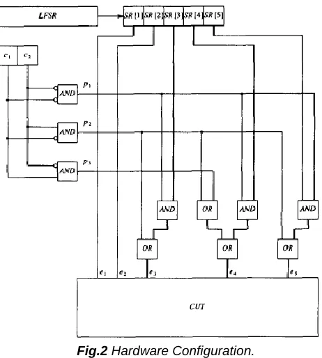
In this section, we illustrate the hardware required to generate weighted random p atterns by the method proposed in this work by giving details of a test pattern generator of the proposed type for the ISCAS-85 benchmark circuit cl 7. Example: Let us consider the expanded tests ti = (---), t2 = (--111) and t3 = (--010), derived by applying Procedures 1 and 2 to c17. The hardware configuration is given in Fig. 2. An LFSR is used for generating pseudorandom patterns. The LFSR drives a 5-cell shift-register. cI, c2 are two cells of a counter, which counts up to two. The contents of the counter indicates the index of the expanded test currently being used (expanded test 1 is represented by c1 = c2 = 0, expanded test 2 is represented by c1 = 0, c2 = 1, and expanded test 3 is represented by c1 = 1, c2 = 0). Inputs 1 and 2 of the circuit under testhave a weight of 0.5 in all expanded tests, and are, therefore, driven directly by the corresponding cell of the shift register. Input 3 should be driven by the third shift-register cell when expanded test 1 is being used, a constant 1 should be applied when t2 is being used, and a constant 0 should be applied when t3 is being used.
Fig.2 Hardware Configuration.
IV. EXPERIMENTAL RESULTS
The method described above was implemented and applied to ISCAS-85 benchmark circuit. Three values of N (the
Test Set For C17
Test 1 2 3 4 5 Fault Detected
1 1 0 0 1 0
2 1 1 0 1 0
3 0 1 1 1 1
4 1 0 1 0 1
2-1, 4-1, 7-1, 3-1, 12-0, 16-1, 17-1
5-1, 12-1, 13-1, 14-1, 3-1, 9-0, 16-0, 17-0
1-1, 9-1, 19-1, 11-1, 3-0, 12-0, 16-1, 17-1
6-1, 8-1, 15-1, 3-0, 9-0, 16-0, 17-0
Test Set For C17
Test 1 2 3 4 5 Fault Detected
1 1 0 1 1 0 2 1 1 0 1 1 3 1 0 1 1 1 4 1 0 0 1 0 5 0 1 0 1 0
3-0,17-1,8-1,12=0,16-0 17-0,3-1,13-1,12-1,5-1,9-0 11-1,9-1
2249
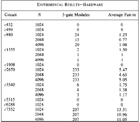
number of random patterns generated for each weight assignment) were used; 1024, 2048 and 4096. For the circuits with number of primary inputs smaller than 200 (all but c2670 and c7552), the value of K was first set by Procedure 1 starting from K equal to the number of primary inputs. Procedure 1 was then executed again with the final value of K obtained. In all cases, pure random tests were generated at the beginning of Procedure 1, to allow easy-to-detect faults to be easy-to-detected with minimum hardware overhead. In Table 4, the hardware required is given based on the configuration suggested in Section II. Our design uses, for each input which is not driven directly by a shift-register cell, a module of three primitive gates. One of the gates has a fan-in of 2, while the other two have a fan-in that depends on the expanded tests selected. In Table 4, after circuit name, the number of three-gate modules is given, followed by the average fan-in to the two gates with fan-in different from 2. For c2670 and N = 1024, K was set to 30 and then decreased. The final value of K was 15. 19 weight assignments were required and all inputs were weighted in at least one assignment. A total of 19 456 random patterns were required. 233 three-gate modules were required, with an average fan-in of 5.47.
Table 4.
The number of XOR gates obtained in [17] should be compared with the number of three-gate modules given in Table 4. It can be seen that the number of effective weights generated and the number of patterns required by the method proposed here are in most cases smaller than the numbers given in [10]. It should also be noted that the actual weight assignments are not given in [10], and may require large numbers of shift-register cells and gates to produce the required weights. The number of gates required is always smaller than the number of gates required in [17]. It should be noted that the number of tests achieved by the method proposed here can be further reduced if the number of tests generated for each weight assignment is allowed to vary. The number of random patterns generated for each weight assignment was fixed to reduce hardware requirements.
V. CONCLUSION
A method for generating weighted pseudo-random patterns, applicable to both combinational and sequential circuits, was described. The method was based on expansion of tests generated by a deterministic test pattern generator to ensure complete fault coverage. Three weights were required (0, 0.5, l}, which are easily produced using an LFSR. The weight assignments were dynamically computed, and the number of 0.5 weights were reduced to match the weight assignments to the remaining faults that had to be detected. Hardware suitable for implementing the proposed method was described, and experimental results were given. Observing that the number of inputs assuming (0, 1)-weights is sometimes large, thus requiring that a large number of inputs be connected to the random pattern generator through additional logic gates, we developed a procedure that minimizes the number of inputs assuming (0, 1)-weights and maximizes the number of inputs that assume only 0.5-weights. For c880, this resulted in a reduction in the number of (0, 1)-weighted inputs from 24 to 3.
REFERENCES
[l] P. H. Bardell, W. H. McAnney, and J. Savir, Built-In Test for VLSI.
[2] E. B. Eichelberaer. E. Lindbloom. J. A. Waicukauski. and T. W. Pseudorandom Techniques. New York: Wiley, 1987.
[3] Williams, Structured Logic Testing. Englewood Cliffs, NJ: Prentice- Hall, 1991.
[4] P. Agrawal and V. D. Agrawal, “Probabilistic analysis of random test generation method for irredundant combinational logic networks,” lE€E Trans. Computers, pp. 691-695, July 1975.
[5] J . Savir. G. S. Ditlow, and P. H. Bardell, “Random pattern testability,” I€€E Trans. Computers, pp. 79-90, Jan. 1984.
[6] P. D. Hortensius et. al., “Cellular automata-Basic pseudorandom number generators for built-in self-test,” l€EE Trans. Computer- Aided Design, pp. 842-859, Aug. 1989.
[7] H. D. Shnurmann, E. Lindbloom, and R. G. Carpenter, “The weighted random test-pattern generator,” I€€€ Trans. Computer, pp. 695-700, July 1975.
[8] R. Lisanke, F. Brglez, A. De Geus, and D. Gregory, “Testabilitydriven random pattern generation,” Intl. Con$ Computer-Aided Design, 1986, pp. 144-147.
[9] H.-J. Wunderlich, “Self test using unequiprobable random patterns,” in Proc. 17th Fault-Tolerant Computing Symposium, 1987,
[10] J. A. Waicukauski and E. Lindbloom, “Fault detection effectiveness of weighted random patterns,” in Proc. Int. Test Conf., pp. 245-250, 1988.
[11] H.-J. Wunderlich, “Multiple distributions for biased random test patterns,” in Proc. Intl. Test Conf., 1988, pp. 236-244.
[12] F. Siavoshi, “WTPGA: A novel weighted test pattern generation approach for VLSI built-in self-test,” in Proc. Intl. Test Conf., 1988,
[14] F. Brglez, C. Gloster, and G. Kedem, “Hardware-based weighted random pattern generation for boundary scan,” in Proc. Intl. Test Conf., 1989, pp. 264-273.
[15] F. Muradali, V. K. Agrawal, and B. Nadeau-Drostie, “A new procedure for weighted random built-in self-test,” in Proc. Intl. Test Conf.., pp. 660-669, 1990; also F. Muradali, M.Sc. Thesis, McGill University, Mar. 1990. [16] F. Brglez and H. Fujiwara, “A neutral netlist of 10
combinational benchmark designs and a special translator in Fortran,” in Proc. International Symposium on Circuits and Systems, June 1985.