1913 IJSTR©2019
Comparative Analysis Of LLC Resonant Converter
And Z Source Resonant DC-DC Converter
Designed For Wide Input Voltage And Variations In
Load
Aniket J Aher, Shrikant S. Mopari
Abstract: In recent years enhancement of power quality has become essential due to tremendous usage of power electronics devices and converters. Moreover, having a wide range of input voltage along with variations in the load has become a common necessity. Resonant converter holds good for all the above parameters and have proved to be far more beneficial than other converters in many aspects such as Efficiency, Power factor, Losses, Voltage Stability and THD. Due to this, resonant converters have attracted many large scale applications such as in Power Distribution, Renewable Energy, Battery chargers for Electric Vehicles, Power factor correction etc. In this paper, two converters, namely LLC Resonant converter and Z-Source resonant DC-DC converter are suggested. This paper also presents a comparative analysis between LLC resonant converter and Z source resonant converter for reliable performance and suitable applications.
Index Terms: SRC, LLC, FHA
————————————————————
1.
INTRODUCTION
The preliminary requirement in today’s world for any application is greater efficiency even with wider load range variation in the input. To meet the above demands, the orthodox LLC resonant converter uses a minor magnetizing inductance. But, due to this, huge losses are generated by high magnetizing current in the Transformer and switching devices. LLC resonant converter that uses auxiliary switches and two resonant tanks was able to achieve high voltage gain characteristics even if the load and input voltage was wide. This resulted in decreasing magnetizing current, reduced losses and efficiency characteristics were significantly improved [1]. If control of phase shift is applied among the primary side and the secondary side of the transformer, the converter may be operated at stable switching frequency. With the help of magnetizing inductance of the transformer, ZVS operation is achieved by the converter in its complete load range and is quite suitable for applications demanding higher power density and efficiency [11].In order to obtain greater efficiency within the provided wide input range, it must be ensured that the power factor of LLC Resonant tank is high [14].
Fig.1 A Conventional Series Resonant Converter
The conventionally used Series resonant converter heavily undergoes from the problem of efficiency degradation if range of the input voltage is wide. A resonant dc-dc converter with a Z-source helps in minimizing range of switching frequency of the converter that further leads to improved converter efficiency. Moreover this converter has the capability to be open-circuited and short-circuited by not letting any harm to the switching devices [2]. Fundamental harmonic approximation (FHA) and various optimal design methods have been tested for maximizing the magnetizing inductance of LLC resonant converter [3]. LLC resonant converted are even being proposed in Distributed power systems due to their low turn on as well as turn off current which results in reduction of switching loss [4]. LLC resonant converters find their presence in electric vehicle chargers whereas double input dc-dc converters have widespread input range of voltage applications in power generation especially renewable energy systems such as solar and wind energy [5], [6], [7] Generally, where all the LLC-SRC converters have all the resonant elements on it input side, some researchers also suggest having one of the resonant inductor at the output side. This helps in implementing the rectifiers which are self-driven. These converters are cost effective, compact and highly efficient and are preferred for voltage step-down applications. ————————————————
Aniket J. Aher PG Student Department of Electrical Engineering, Government Engineering College Aurangabad, India 431005
aniketjaher@gmail.com
Shrikant S. Mopari Assistant Professor Department of Electrical Engineering, Government Engineering College Aurangabad, India 431005
1914 IJSTR©2019
[8]. LLC resonant converter fed by a Cuk converter have also been developed having widespread applications in electric vehicle battery chargers. The primary function of the Cuk converter used here is the power factor correction [9]. Efficiency of the LLC resonant converter is proportional to its switching frequency. In order to achieve maximum efficiency, the switching frequency and the resonant frequency must be equal. Tracking of resonant frequency is also being practiced. [10]. Owing to the complexity of the Z-Source network, the investigation about Z-Source converter along with its soft witching characteristic is seldom practiced. Due to the presence of Z-Source network, the Z-Source dc-dc converter provides great reliability, which apparently suits the application of dc power distribution [12]. Z-Source resonant converter also finds its usage in power factor correction (PFC) applications [13].
2 RESONANT CONVERTER
In an AC circuit having capacitor or inductor, when frequency of AC is changed gradually, impedance of the circuit becomes maximum or minimum. This condition is termed as Resonance and the circuit is named Resonant circuit. When impedance of the circuit is minimum and current is maximum, current and source e.m.f is in phase and we say that there is resonance in the circuit. A given circuit having a constant value of inductor and capacitor can be in resonance for a particular frequency. The frequency of AC for which resonance takes place and maximum current flows through the circuit is called resonant frequency. It is given by the formula Fr = 1/2π √LC. Resonant converters are a type of electrical converter which comprises of a network having inductors plus capacitors called resonant tank adjusted to resonate at a specific frequency. They may be broadly classified as Series resonant converter, Parallel resonant converter, Class E resonant converter, ZVS resonant converter, ZCS resonant converter. When impedance of the circuit is minimum and current is maximum, current and source e.m.f is in phase and we say that there is resonance in the circuit.
2.1SERIES RESONANT CIRCUIT:
When alternating current of different frequency is sent through series resonant circuit, it offers minimum impedance to current of resonant frequency and high impedance to other frequency currents. i.e. it accepts current of resonant frequency only and rejects current of other frequencies therefore it is also known as Acceptor circuit. This circuit has wide range of applications in radio receivers and television for tuning the signal from any desired channel or transmitting station. A series resonance curve is shown below from which we can conclude that at resonance rms current becomes maximum.
2.2 Parallel resonant circuit: When alternating current of different frequencies are sent through parallel resonant circuits, it offers a very high impedance to current of resonant frequency and allow current of other frequencies to pass through it, hence it is also called as rejector circuit. This circuit is finds its applications in wireless transmission, radio communication and as a filter circuit.
3 NOVEL LLC RESONANT CONVERTER:
The conventional LLC resonant converters are used when the range of input voltage and variation in output load is wide.
These converters need a minor magnetizing inductance and work with extensive switching frequency deviations, due to which the converter optimization becomes complicated. To overcome this hurdle, a LLC converter having wide input and wide output (WIWO) voltage with load range is recommended. The suggested topology of LLC resonant converter includes a circuit having two resonant tanks having two transformers, resonant capacitors including two auxiliary switches which are introduced into the secondary side
Fig. 2 Suggested LLC Resonant Converter
To maintain a constant output voltage in low load conditions and wide range of input voltage, an extensive control range of switching frequency has to be applied, which results in very low efficiency. To counter above drawbacks, LLC resonant converter is suggested where duty cycle of the auxiliary switches controls the output voltage, Moreover, the efficiency is also improved.
1915 IJSTR©2019
Experimental waveforms of the proposed converter and table of necessary parameters are shown below
Table 1
Significant parameters of proposed LLC Converter
Sr No Parameter Sign Value
1 Rated input voltage Vin 200V
2 Rated output voltage Vo 199.5V
3 Resonant inductor Lr 2500 nH
4 Resonant capacitor Cr 2200 mF
5 Magnetizing inductor Lm 110 μH
6 Filter capacitor Lf 40H
7 Filter inductor Cf 10000 nF
8 Load RL 1kΩ
Fig.4 Voltage vs. Time waveform
Fig.5 Current vs. Time waveform
4
Z SOURCE RESONANT CONVERTERResonant converters have the ability to attain very little switching loss because of its soft switching characteristic. Most commonly used topology, SRC suffers from a major drawback of having poor light load efficiency circulating currents which at the end do not contribute in the power transfer. Moreover output of SRC usually is equal to input voltage or smaller than that. We can say that SRC operates only in step down mode i.e. buck operation. When range of input voltage is very widespread SRC might fail to perform because of its low efficiency at max input voltage. To overcome this issue LLC series resonant converter in which resonant element used is a transformer magnetizing inductance has been presented earlier which showed good performance. But when the load increases, the magnetizing inductance becomes least effective and ultimately is attains properties of SRC. To solve this problem, the magnetizing inductance is to be reduced further
or characteristic impedance of the network is to be minimized. This might result in increase in switch turn off current leading to efficiency drop. So for the system demanding both wide load variation and wide input voltage the LLC- SRC may not be valid. So to eliminate the problems mentioned above, a resonant dc-dc converter having Z-source impedance network in the middle of the main switching device and power source is suggested.
Fig.6 Proposed Z-Source Converter
Therefore the desired buck as well as boost operation mode of operation can be achieved and it has the ability to be open circuited and short circuited without damaging the switches. The buck plus boost function utilized here eventually contributes to improved light load efficiency. Efforts are being made to reduce the capacitors and bulky inductors quite significantly in order to minimize converter cost and volume.
Fig. 7 Simulink Model of Projected Z-Source Resonant DC-DC Converter
Experimental waveforms of the proposed converter and a table of necessary parameters are shown below.
Table 2
Key parameters of proposed Z-Source Resonant DC-DC Converter
Sr No Parameter Sign Value
1 Rated input voltage Vin 200V
2 Rated output voltage Vo 197.5V
3 Filter inductor Lf 95
4 Filter capacitor Cf 9000 n
5 Magnetizing inductor Lm 110 μH 6 Z-Source
Network
Lz 100 μH
1916 IJSTR©2019
8 Load RL 1k Ω
Fig.8 Voltage vs. Time waveform
Fig.9 Current vs. Time waveform
5 COMPARATIVE ANALYSIS
Model of both the converters were developed in MATLAB Simulink and were tested at different voltages. Below a glimpse of their performance parameters is formulated in a tabular format for better understanding and interpretation.
Table 3
Variation of Power factor and THD at different Voltage ranges for LLC Resonant Converter
Voltage THD Power factor
50 0.7081 0.8814
80 0.7081 0.8814
100 0.7073 0.8814
120 0.7067 0.8814
150 0.7062 0.8814
180 0.7058 0.8814
200 0.7056 0.8814
220 0.7056 0.8814
Table 4
Variation of Power factor and THD at different Voltage ranges for Z-Source Resonant DC-DC Converter.
Voltage THD Power factor
50 0.7016 0.8186
80 0.6992 0.8195
100 0.6984 0.8198
120 0.6979 0.8200
150 0.6974 0.8202
180 0.6972 0.8204
200 0.6969 0.8204
220 0.6967 0.8205
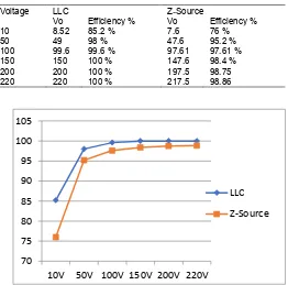
From the experimental values tabulated above, it is very clear that the Power factor and THD for each converter is somewhat similar and only shows a slight variation. By overall observation we can conclude that LLC resonant converter has better Power factor and THD.To arrive at a stiff conclusion and have a better idea regarding the performance, a table for tabular representation along with a graph for pictorial representation of the converter efficiencies is presented below.
Table 5
Comparison of Efficiencies at different voltages
Voltage LLC Z-Source
Vo Efficiency % Vo Efficiency %
10 8.52 85.2 % 7.6 76 %
50 49 98 % 47.6 95.2 %
100 99.6 99.6 % 97.61 97.61 %
150 150 100 % 147.6 98.4 %
200 200 100 % 197.5 98.75
220 220 100 % 217.5 98.86
Fig.9 Comparison of Efficiencies at different voltages
6
CONCLUSIONIn this paper, LLC Resonant converter and resonant converter with a Z-Source having wide-ranging input voltage and variations in load is advised along with its comparative analysis.
Series Resonant converters suffer from number of disadvantages like poor light load efficiency and operating in only step down mode.
Proposed Converters operate in both buck and boost mode and have also shown greater efficiencies which make them suitable for high power density applications such as power generation, distribution and in renewable sectors. Moreover, they are cost effective and compact.
LLC resonant converter proves to be more superior to Z-Source resonant DC-DC converter due to its impressive efficiency, Power factor and THD.
.
REFERENCES
[1] Bong-Gun Chung, Kwang-Ho Yoon, Sopheak Phum, Eun-Soo Kim, Jong-Seob Won, “A Novel LLC Resonant Converter for Wide Input Voltage & Load
70 75 80 85 90 95 100 105
10V 50V 100V 150V 200V 220V LLC
1917 IJSTR©2019
Variation,” 8th International Conference on Power Electronics- ECCE Asia May 30, 2011.
[2] Honnyong Cha, Fang Z. Peng, and Dongwook Yoo, “Z-Source DC-DC Converter for Wide input Voltage and Load Variation,” The 2010 international Power Electronics Conference.
[3] Zhijian Fang, Shanxu Duan, C Chen and Xi Chen, “Optimal Design Method for LLC Resonant Converter with Wide Range Output Voltage,” IEEE Conference 2013.
[4] Bo Yang and Fred C. Lee, Alpha J. Zhang and Guisong Huang, “LLC Resonant Converter for Front End DC/DC Conversion,” IEEE Conference 2002. [5] Kerim Colak, Erdem Asa, Dariusz Czarkowski, “A
Comparison Analysis of CLL and LLC Resonant Converter for Multi-phase Applications,” IEEE Conference 2015.
[6] Hu R. J., Zeng J,Liu J. F, “A Double-input DC-DC Converter for Wide-input-voltage-range Application,” [7] Ji-Hoon Park and Jae-Kuk Kim, “A Non-Isolated
Dual-Input DC-DC Converter with Wide Dual-Input Voltage Range for Renewable Energy Sources,” IEEE Conference 2017.
[8] Sheng-Yang Yu, “A New Compact and High Efficiency Resonant Converter,” IEEE Conference 2016.
[9] Rahul Pandey and Bhim Singh, “A Power Factor Corrected LLC Resonant Converter for Electric Vehicle Charger Using Cuk Converter,” IEEE Conference 2018
[10] Iresha Poonahela, Sertac Bayhan, Haitham Abu-Rub, “A Simple Resonant Frequency Tracking Technique for LLC Resonant Converters,” 6th International Conference on Renewable Energy Research & Applications, IEEE 2017
[11] Francisco Canales, Peter Barbosa and Fred C. Lee, “A Wide Input Voltage and Load Output Variations Fixed-Frequency AVS DC/DC LLC Resonant Converter for High-Power Applications,” IEEE Conference 2002
12] Xiaoliang Dong, Yazhou Luo, Jiang Li and Guoqing Li, “Z-Source Resonant Soft Switching Converter for Flexible DC Power Distribution,” IEEE Conference 2016
[13] Nomar S. González-Santini, Hulong Zeng, Yaodong Yu, and Fang Zheng Peng, “Z-Source Resonant Converter with Power Factor Correction for Wireless Power Transfer Applications,” IEEE
Transcations on Power Electronics 2016