54
Implementation of Switching Instant Optimization on a Two-Level
Inverter-Fed Induction Motor Drive Controlled using MPFC
B. Nishant
1,S. Sridhar
2, B. Sree Bhavani
31
PG Scholar, Dept. Of Electrical & Electronics Engineering, JNTUACEA, Anantapuramu, A.P., India
2
Asst.Professor, Dept. Of Electrical & Electronics Engineering, JNTUACEA, Anantapuramu, A.P., India
3
M-Tech, Dept. Of Electrical & Electronics Engineering, SNIST, Hyderabad, Telangana, India
---***---ABSTRACT-In order to get the high performance of
induction motor drives model predictive torque control (MPTC) can be consider as one of the best schemes. When compared with direct torque control (DTC),MPTC is accurate in its voltage vector selection by employing system model directly with the finite switching states. However, it requires tuning work for stator flux weighting factor. This tuning work is time-consuming and tedious process. To solve this problem, this paper proposes model predictive flux control(MPFC) for two-level inverter fed induction motor (IM) drives. This is achieved by converting stator flux magnitude and torque into a single equivalent reference frame of stator flux vector. As only one stator flux is required for error tracking, the usage of weighting factor is eliminated as both have same reference. In this paper proposed MPFC with and without switching instant optimization both are implemented. The results obtained show the effectiveness of both the results.
INDE740X TERMS:Field-oriented control (FOC), Direct torque control (DTC), Model predictive control (MPC),Model predictive torque control (MPTC),Model predictive flux control (MPFC),Induction motor (IM).
1.INTRODUCTION
Field-oriented control (FOC) and direct torque control (DTC) are two methods used effectively for high performance control of induction motor (IM) drives. The direct torque control (DTC) is suitable for variable speed drives especially in cases where torque control is more important than- speed control. In DTC, the voltage vector selection is done directly from predefined switching table according to the position of stator flux and error signs of both flux and torque. The advantages of the DTC are fast transient torque response and its simple structure. However, due to the hysteresis characteristics of control algorithm, DTC has two drawbacks. First, variable switching frequency and the second one is high flux and torque ripples. Among the available methods, MPC is recently introduced as an effective alternative to the conventional DTC and has drawn increased attention from both academic and industrial communities.
The application of model predictive control (MPC) in electrical drives includes model predictive current control (MPCC) and model predictive torque control (MPTC). MPTC is performed in stationary frame, hence it is much simpler. In MPTC, torque and stator flux are predicted in accordance to the system model. The obtained optimal output of controller is evaluated based on predefined optimization criteria.
MPTC can directly predict the evolution of variables concerned, such as torque and stator flux. A proper tuning of weighting factor for stator flux is required as both torque and
stator flux have different units and amplitudes. Tuning of weighting factor is still a time-consuming problem as it is done based on empirical procedures.By evaluating the influence of each possible voltage vector, the one minimizing the torque and flux errors is selected as the best voltage vector. By doing this the vector selected from MPTC is more accurate. However, as the number of voltage vectors provided by a two-level inverter is rather limited (only eight vectors), the torque and flux ripples obtained from conventional MPTC are higher than those obtained from a multi-level inverter. To eliminate the usage of weighting factor the relationship between torque and stator flux is investigated.
In order to improve the steady-state performance of MPTC, the sampling frequency has to be high, which requires high computational ability. In MPTC, the voltage vector selected is applied at next control period. For better steady state performance recently, MPTC is implemented with duty cycle control. In this control period is investigated in two parts by investing a non-zero vector and a zero vector. Furthermore, high amount of calculation is required in MPTC due to the predictions of both stator flux and current for each voltage vector. Hence, in MPTC improving the steady torque performance and reducing the control complexity have become important constraints. Even after applying duty cycle control still suffers from tuning of weighting factor as both stator flux and torque are still involved in cost function minimization.
In DTC, it has been known that high torque ripple is partly caused by the application of a single voltage vector during the whole control period. In MPTC, although the selected vector is more accurate and effective in reducing torque and flux errors, applying a single voltage vector during the whole control period still fails to reduce the torque and flux errors to the minimal value. So to eliminate the weighting factor in conventional MPTC, this paper proposes model predictive flux control (MPFC). The torque and flux vector are translated into a single reference new stator flux vector. As both torque and stator flux are now converted into a single reference frame they both have same dimension resulting in the elimination of weighting factor tuning. This makes implementation of MPFC much easier in designing of real time applications compared to MPTC. In this paper, implementation on low and medium two-level IM drives with less designing complexity is achieved with the proposed MPFC. We discussed about two types of MPFC in this paper based on the application of control vector. In the first method, only one voltage vector is applied during one control period. In the second method, to achieve better steady-state performance switching instant of selected voltage vector is investigated, through which torque ripple minimization is achieved by minimizing the tracking of stator flux vector error.Simulation results prove that, better steady-state
55 performance is achieved for the proposed MPFC especially in
the low-speed range.
II. DYNAMIC EQUATIONS OF IM
The dynamic equations of IM with stator flux 𝜓𝑠and stator currents 𝑖𝑠as state variables can be expressed in stationary frame
x = Ax + Bµ(1)
where X= 𝑖𝑠 𝜓𝑠 𝑇are state variables, u= us is the stator voltage vector, and
A= −𝜆 𝑅𝑠𝐿𝑟+ 𝑅−𝑅𝑟𝐿𝑠 + 𝑗𝜔𝑟 𝜆 𝑅𝑟− 𝑗𝐿𝑟𝜔𝑟
𝑠 0
(2)
B= 𝜆𝐿𝑟
1 (3)
𝑅𝑠,𝑅𝑟stator resistance, rotor resistance
𝐿𝑠, 𝐿𝑟, Lmstator inductance, rotor inductance and mutual
inductance.
ωrelectrical rotor speed
λ= 1
𝐿𝑠𝐿𝑟−𝐿𝑚2
The prediction of the stator current and stator flux at the nextSampling instant can be obtained from (1). To ensure good accuracy of the prediction, second-order Euler method is employed.
Fig.1. Control diagram of conventional MPTC.
𝑥𝑝 𝑘 + 1 = 𝑥 𝑘 + 𝑇𝑠𝑐 𝐴𝑥 𝑘 + 𝐵𝑢𝑠 𝑘 𝑥 𝑘 + 1 = 𝑥𝑝 𝑘 + 1 +
𝑇𝑠𝑐
2 𝐴 𝑥𝑝 𝑘 + 1 − 𝑥 𝑘 (4) where 𝑇𝑠𝑐is control period xp k + 1 is predictor-corrector of state vector;
x k + 1 = is k + 1 ψs k + 1 T
is predicted state vector for stator current and stator flux. The main difference between xp(k + 1) and x(k + 1) is that xp(k+1)
is calculated as a rough approximation of x(k+1) in the first step, which is equivalent to forward Euler integration. The value of xp(k + 1) is refined in the second step to obtain more
accurate result of x(k + 1), which is equivalent to trapezoidal integration method . It is possible to use more advanced method to obtain accurate discretization of (1), such as Cayley–Hamilton theorem in, but the computation burden will
be significantly increased, so it is not adopted in this paper. The electromagnetic torque can be predicted as
𝑇𝑒 k + 1 = 23𝑁𝑝𝜓𝑠 𝑘 + 1 ⊗ 𝑖𝑠 k + 1 (5)
whereNp is the number of pole pairs and ⊗represents cross product.
Omitting the tedious deduction process, the differentiation of torque Te with respect to time t can be obtained from (1) and(5) 𝑑𝑇𝑒 𝑑𝑡=1.5𝑁𝑝λ𝐿𝑚 −𝜆 𝑅𝑠𝐿𝑟+ 𝑅𝑟𝐿𝑠 𝐼𝑚 𝜓𝑟 ∗𝜓 𝑠 − 𝜔𝑟𝑅𝑒𝜓𝑟∗𝜓𝑠+𝐼𝑚𝜓𝑟∗𝑢𝑠(6)
where٭represents the conjugation of a complex vector. The equation in (6) provides a practical method to calculate the slope of torque, which is useful for the aim of improving torque performance in Section III. For simplicity, the torque slope caused by a zero vector u0and a nonzero voltage vector
uiare represented by s0and si, respectively, which are
expressed as 𝑠0= 𝑑𝑇𝑒 𝑑𝑡 |𝑢𝑠=0= 1.5𝑁𝑝λ𝐿𝑚 −𝜆 𝑅𝑠𝐿𝑟+ 𝑅𝑟𝐿𝑠 𝐼𝑚 𝜓𝑟 ∗ 𝜓𝑠 − 𝜔𝑟𝑅𝑒𝜓𝑟∗𝜓𝑠 (7) 𝑠𝑖 =𝑑𝑇𝑒 𝑑𝑡 |𝑢𝑠=𝑢𝑝 = 𝑠0+ 1.5𝑁𝑝λ𝐿𝑚 𝜓𝑟 ∗ 𝑢𝑖 (8) III. CONVENTIONAL MPTC
The MPTC control diagram considering one-step delay compensation is shown in fig1, where to generate torque reference a PI speed controller is used. From the system model, conventional scheme predicts torque and flux vectors from all the available voltage vector provided by the inverter and from them by the minimization of cost function the best voltage vector is determined consisting of both flux and torque error. The control diagram consisting of A. Flux and torque estimation or predictionB. Cost function minimization C. Machine magnetization
A. State Estimation
To maintain good performance of MPTC the flux and torque estimation should be accurate. A full order observer is adopted and it is having good accuracy over a wide speed range. The error feedback of stator current is introduced, the accuracy of estimation is increased and the observer is more robust against the motor parameter variations. The mathematical model of the observer is based on the IM model in (1), which is expressed as
dx
dt = Ax + Bu + G is− i s (9)
Where 𝑥 = 𝑖𝑠 𝜓 𝑠 𝑇are the estimated state variables. The observer poles of IM drives is proportional to the poles of IM and its factor is greater than one (k>1) which produces high imaginary part at high speed and is harmful to the system stability. To remedy these problems the imaginary part of the observer poles should remain unchanged and real part of observer poles should be changed to left in the complex plane
56 compared to the poles of IM. However, this leads to
complicated expressions of observer gains. so to eliminate all those problems a very simple constant gain matrix G is employed to improve stability of the observer and it can be expressed as
G = − b 2b λLr
(10)
whereb is negative constant gain. This pole placement method can improve the convergence and stability of observer especially at high speed and is simple to implement.
B. Vector Selection
In conventional MPTC the stator flux and electromagnetic torque at (k + 1)th instant are predicted using predictive model,with the variables of is(k) and ψs(k) as the initial states.
The aim of the cost function is to force both stator flux and torque to track their respective reference value. In other words error between estimated value and reference value of stator flux and torque should be minimized.
J= Teref − Tek+1 +kψ ψsref − ψsk+1 (11)
where𝑘𝜓denotes the weighting factor for stator flux. The tuning of 𝑘𝜓 is a non-trivial and time consuming process. To assign the same weight on torque and stator-flux,𝑘𝜓is usually chosen as
kψ= ψTn
sn (12)
where𝑇𝑛is the rated torque and |𝜓𝑠 | is the rated amplitude of stator flux. It should be noted that the weighting factor 𝑘𝜓 in (12) is only used as a starting point for tuning work and the final practical value of 𝑘𝜓may be larger than that in (12). As can be seen from the first row of matrix A in (2), the prediction ofis(k + 1) is complicated. As the stator current is not directly used in the cost function of conventional MPTC,the prediction of stator current may be eliminated for the aim of control complexity reduction. To predict the torque at (k + 1)th instant without the prediction of stator current, (5) is replaced by
Te k + 1 = 3
2Npψs k + 1 ⊗ isλ k (13)
where𝑖𝑠𝜆 k is calculated based on the variables at kth instant. In order to reduce this delay, 𝑘 + 2 th instant variables are predicted for the evaluation of cost function rather than 𝑘 + 1 th instant. The cost function can be represented as (14) after considering the unit step delay can be written from (12) as follows
J= Teref − Tek+2 +kψ ψsref − ψsk+2 (14)
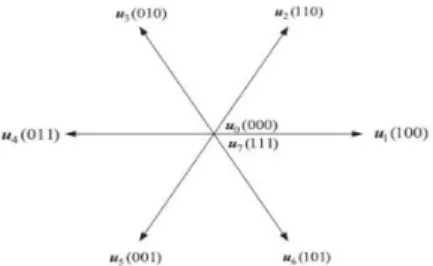
For two-level IM drives, There are eight discrete voltage vectors available: u0 ,u1. . .u7 for a two-level inverter-fed IM drive as shown in fig.3. The best voltage vector is selected after the evaluation of cost function for all the available vectors and the best one is applied at the next control period.
Fig. 2.Voltage vector and corresponding switching states of two level inverter.
IV. PROPOSED MPFC A. Principle of Basic MPFC
To achieve simultaneous control of torque and stator flux a proper weighting factor for stator flux is necessary as torque and stator flux are combined into a single cost function. Tuning of weighting factor is not only a time-consuming process but also lacking of proper theoretical design it results in a nontrivial tuning work. In this we design a new stator flux vector reference based on IM model in equivalence with the original torque and stator flux vectors. Now both quantities are in single reference weighting factor is eliminated in proposed MPFC.
When the rotor speed is below rated speed, the magnitude of stator flux reference ψsrefis set to the rated value ψsref in this
paper,
| ψsref | = ψsref(15)
The torque can be expressed as a cross product of stator -flux and rotor flux ,which is expressed as,
Te=
3
2p λ Lm(ψr⊗ψs)(16)
From (16), if the rotor-flux ψr is already known, the references
of torque and stator-flux should satisfy with the following equation Teref = 3 2p λ Lm (ψr ⊗ψs ref )(17)
Based on (15) and (16), stator flux reference ψsref is expressed
by ψsref and 𝑇𝑒𝑟𝑒𝑓 as follows ψsref =ψsref . exp (
j
.
ψsref)(18)ψsref =
ψr+ arcsin ( Teref 3 2 Pλ Lm |ψr ref| ||ψ sref| )(19)Similarly, the stator flux vector referenceψsref at (k+2)th
instant has to be determined for the delay compensation in the conventional MPTC. To know the value of ψsref we first need
to know the information of 𝑇𝑒𝑟𝑒𝑓 and ψr at (k+2)th instant.
If the sampling is very much higher than the band-width of outer speed control loops (10) then the future reference of torque can be considered to be approximately equal to the value of present state of reference. The value of ψr at (k+2)th
57 flux at (k+1)th instant is predicted first from (k+1)th stator
flux and stator current as follows, ψrk+1 = Lr Lm ψs k+1 - 1 λ Lm is k+1
(20)
whereψsk+1 and isk+1 are predicted from (4).
ψrk+1 represent rotor flux at (k+1)th instant and ψsk+1 and isk+1
represent stator flux and current at (k+1)th instant. Now using the value of ψrk+1 we should obtain the value of ψrk+2 with the
help of (9) and (19) represented by following equation ψrk+2 = ψrk+1 + Tsc ( Rr Lm Lr is k+1 – (Rr Lr − j ωr)ψr k+1 ) (21) Based on the predicted value of ψrk+2 from (21), the phase
angle reference of ψsref at (k+2)th instant is predicted as
follows
ψsref =
ψrk+2 + arcsin ( Teref 3 2 Pλ Lm |ψr k +2| ||ψ sref| )(22)Final stator flux reference ψsrefcan be calculated using (18)
and (21) which is equivalent to original stator flux amplitude reference and torque reference. After calculating that we can derive a cost function similar to (14) which can force stator flux ψs to track its reference, which is expressed as
J1=|ψsref- ψsk+2 | (23)
From equation (23) it is clear that cost function minimization does not require weighting factor. The prediction of stator flux at (k+2)th instant is as follows,
ψrk+2 = ψrk+1 + (usk+1 - Rs isk+1)Tsc (24)
where ψsk+1 and isk+1 are predicted from (9) to compensate the
influence of unit step delay. To summarize the process of the proposed MPFC, first we have to measure dc-link voltage, rotor speed at kth instant and stator current. Now estimate the stator flux and predict isk+1 and ψsk+1 with the help of their
initial states. The desired phase angle ψsref using (22) after
predicting the values of ψrk+2 from (19) and ψsk+2 from (24).
Final new stator flux reference in accordance to (18) and it is now substituted into (23) to select the best voltage vector minimizing.
B. Improved MPFC with Switching Instant Optimization
From equation (23) it is clear that the weighting factor of stator flux is eliminated by transforming the torque and stator flux references into a single reference frame so that they both have same unit i.e., into an equivalent reference of stator flux vector. With this practicability of MPFC is improved as offline tuning work is eliminated. However, applying selected voltage vector during the whole control period is still being considerable torque ripple and current harmonics which is similar to conventional MPTC.
In the improved MPFC with switching instant optimization, to improve the steady-state performance of the scheme further the switching instant of the selected voltage vector is being optimized. The old voltage vector during the last control period will be applied first in proposed MPFC followed by the selected voltage vector. This is different from the MPTC with duty cycle control which applies the selected voltage vector at the beginning of next control period. The stator flux at the end of next control period can be represented with the following equation
ψsk+2 = ψsk+1 + fkold topt + fik+1(Tsc – Topt)(25)
where fold and fik+1 (i
ε {0,1,,,,,,7}
) are slopes of stator fluxvector uoldapplies at previous period and a selected voltage
vector usik+1 , respectively. topt is the optimal duration of uold.
The stator flux slope usik+1is assumed to be constant for a short
period of time and can be calculated as follows
fik+1 =
𝑑ψ𝑠1
𝑑𝑡 = usi
k+1
- Rsisk+1 (26)
On substituting (25) into (23), the cost function is considered as a function of 𝑡𝑜𝑝𝑡 , namely J1 = J1(𝑡𝑜𝑝𝑡). Minimizing (23) is
equivalent to solving the following equation: ժ J1 (𝑡𝑜𝑝𝑡)
ժ 𝑡𝑜𝑝𝑡 = 0(27)
On combining (25) to (27), the optimal switching instant is finally derived as
topt =
(ψ𝑠𝑟𝑒𝑓− ψ𝑠𝑘+1−𝑓𝑖𝑘+1T𝑠𝑐 ) ʘ (𝑓𝑜𝑙𝑑− 𝑓𝑖𝑘+1)
|𝑓𝑜𝑙𝑑− 𝑓𝑖𝑘+1| 2 (28)
whereʘ represents the dot product of two complex vectors. 𝑡𝑜𝑝𝑡is limited to the range of [0, Tsc] for the aim of protection
in practical application.
The optimal switching instant 𝑡𝑜𝑝𝑡 is calculated for each feasible voltage vector ψsk+1 (i
ε
{1,2,,,,,,7}) according to(28). After determination of 𝑡𝑜𝑝𝑡 for a given voltage vector, stator flux at (k+2)th instant is predicted as follows ψsik+2 = ψsk+1 + (uold – usik+1)ti + (usik+1 - Rsis)Tsc (29)
The value of ψsik+2 is evaluated by the cost function from the
equation (23) to determine the best voltage vector and its optimal duration.
At the end of next control period, by following the procedure mentioned above the minimal tracking of stator flux vector is achieved. However, there is high possibility of having high deviation of stator flux at switching instant may occur. We can observe this from the two possible stator flux trajectories shown in Fig. 3.
58 Fig. 3. Two trajectories of stator flux during one control period.
Although both stator flux trajectories (shown as a and b in Fig 3) can reach the stator flux reference at the end of control period, the trajectory a is preferred because it is smoother than b and also has small deviation from the reference vector during the whole control period.
Fig.4. Control diagram of proposed MPFC with switching instant optimization.
To prevent high deviation of stator flux during the control period, a penalty on deviation at the switching instant is added in cost function (23), namely
j2 = | ψsref - ψsk+2 | + |ψsref - |ψst || (30)
where stator flux ψst is the stator flux vector at the optimal
switching instant and it can be obtained as follows: ψst = ψsk+1 + uoldti(31)
Hence, after ψsik+2 and ψst are obtained from (29) and (31) for
a given voltage vector usik+1 are evaluated from the cost
function represented in (30). The best voltage vector uopt with
its optimal switching instant topt minimizing is selected among
all the voltage vectors together with their optimal switching instants while evaluating with their cost function and applied in the next control period. The overall control diagram of proposed MPFC is shown in Fig.4.
TABLE I
MACHINE AND CONTROL PARAMETERS
.
IV. SIMULATION RESULTS
The proposed MPFC is simulated in the environment of MATLAB/Simulink to validate its effectiveness. The machine and control parameters are listed in Table I. For convenience, the basic MPFC without flux weighting factor is referred as method I and the improved MPFC with switching instant optimization is refereed as method II in the following text respectively.
Fig.5. and Fig.6.shows the starting response from standstill to 1500r/min for both methods. The stator flux is first established using pre-excitation and during the acceleration stage the torque is limited to 120% rated value (16.8N.m). At t=0.4sec an external load with rated value (14N.m) is applied suddenly to the machine. From top to bottom, the curves shown in Fig.5 and Fig.6. are speed, torque, stator flux and stator current respectively. It is clearly seen that the proposed MPTC works well over a wide speed range and exhibits strong robustness against load disturbance. Similarly dynamic responses can be observed in method II, but with much lower torque and current ripples.
Fig.5. Simulated starting responses from standstill to 1500r/min for method I
59 Fig.6. Simulated starting responses from standstill to 1500r/minfor
method II
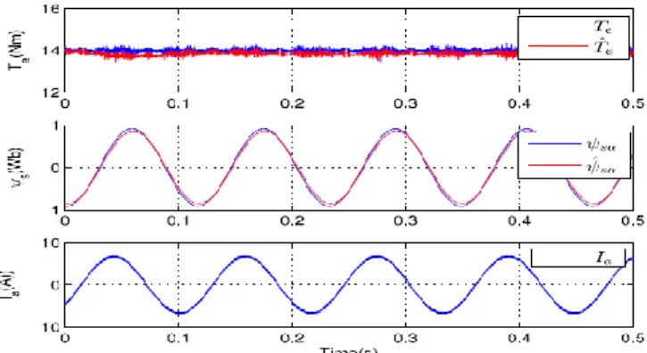
A more detailed steady-state wave-form of torque and stator flux with 100% rated torque are observed in Fig.7 and Fig.8. It can be observed clearly from the result that both torque and flux ripples in method II are much lower than those in method I. With this we can confirm the effectiveness of method II with switching instant optimization.
Fig. 7. Simulated steady state performance of method I
To know the influence of machine parameters variations on performance of system observe Fig.9. and Fig.10. Simulated responses of method II at low and high speeds when stator and rotor resistances are increased by 50% and 100% respectively are represented in Fig.9 and Fig.10.
Fig.8. Simulated steady state performance of method II
Fig. 9. With mismatched machine parameters of method II with both stator and rotor resistances are increased by 50% at 150r/min
Fig. 10. With mismatched machine parameters of method II with both stator and rotor resistances are increased by 100% at 1500r/min
From the simulated results it is clear that system works well at both low and high speeds, even if the stator and rotor resistances vary significantly from their actual value. Current is very sinusoidal in shape. Only very minor tracking error of stator flux can be observed in low-speed operation and the flux error at high speed is negligible as we use only a closed-loop full-order observer is employed. The simulation results prove that the proposed method has some robustness against machine parameter variations. Hence, method II is more effective in terms of torque, stator flux and current ripples. This shows us that method II would be more helpful in applications requiring higher steady state performance, while in applications where low switching frequency is major concern method I can be preferred.
60 V. CONCLUSION
In two-level inverter fed IM we have limited voltage vectors and it can be applied to conventional MPTC then it gives high torque ripples at steady state conditions. To improve the steady state performance, torque ripples and to eliminate the requirement of tuning of stator flux weighting factor we introduceswitching instant optimization in MPFC. This is achieved by a proper investigation about the stator flux and torque relation-ship in a two-level IM drive. A new stator flux reference vector is formulated using original torque and flux references in which both stator flux and torque are brought together into a single unit. Thus eliminating tuning of weighting factor is achieved. We have two different methods in this paper. One is mainly related to the low switching frequency and second method is entirely on steady-state performance improvement without having impact on torque or flux ripples and current harmonics.By observing the performance with much lower sampling frequency proposed MPFC gives better performance and also improves the practicability of the system.
REFERENCES
[1] Y. Zhang and J. Zhu, “A novel duty cycle control strategy to reduce both torque and flux ripples for DTC of
permanent magnet synchronous motordrives with switching frequency reduction,” IEEE Trans. Power
Electron., vol. 26, no. 10, pp. 3055–3067, Oct. 2011..
[2] J. Beerten, J. Verveckken, and J. Driesen, “Predictive direct torque control for flux and torque ripple reduction,”
IEEE Trans. Ind. Electron., vol. 57, no. 1, pp. 404–412,
Jan. 2010.
[3] S. A. Davari, D. A. Khaburi, F. Wang, and R. M. Kennel, “Using fullorder and reduced order observers for robust sensorless predictive torquecontrol of induction motors,”
IEEE Trans. Power Electron., vol. 27, no. 7,pp. 3424–
3433, Jul. 2012.
[4] C. A. Rojas, J. Rodriguez, F. Villarroel, J. R. Espinoza, C. A. Silva, andM. Trincado, “Predictive torque and flux control without weighting factors,”IEEE Trans. Ind.
Electron., vol. 60, no. 2, pp. 681–690, Feb. 2013.
[5] J.-K.KangandS.-K.Sul,“New direct torque control of induction motor for minimum torque ripple and constant switching frequency,” IEEE Trans. Ind. Appl., vol. 35, no. 5, pp. 1076–1082, Sep./Oct. 1999.
[6] Y. Zhang, W. Xie, Z. Li, and Y. Zhang, “Model predictive direct powercontrol of a PWM rectifier with duty cycle optimization,” IEEE Trans.Power Electron., vol. 28, no. 11, pp. 5343–5351, 2013.
[7] H. Miranda, P. Cortes, J. Yuz, and J. Rodriguez,
“Predictive torque controlof induction machines based on state-space models,” IEEE Trans. Ind.Electron., vol. 56, no. 6, pp. 1916–1924, Jun. 2009.
[8] Y. Zhang and H.Yang, “Torque ripple reduction of model predictive torquecontrol of induction motor drives,” in
Proc. IEEE Energy Convers. Congr.Expo., 2013, pp.
1176–1183.
[9] M. Nemec, D. Nedeljkovic, and V. Ambrozic, “Predictive torque controlof induction machines using immediate flux control,” IEEE Trans. Ind.Electron., vol. 54, no. 4, pp. 2009–2017, Aug. 2007.
[10] B. Kenny and R. Lorenz, “Stator- and rotor-flux-based deadbeat directtorque control of induction machines,”
IEEE Trans. Ind. Appl., vol. 39,no. 4, pp. 1093–1101,
Jul./Aug. 2003.
[11] P. Cortes, J. Rodriguez, C. Silva, and A. Flores, “Delay compensation inmodel predictive current control of a
three-phase inverter,” IEEE Trans.Ind. Electron., vol. 59, no. 2, pp. 1323–1325, Feb. 2012.
[12] Y. Zhang and H. Yang, “Generalized two-vector-based model-predictive torque control of induction motor drives,” IEEE Trans. Power Electron., vol. 30, no. 7, pp. 3818–3829, Jul. 2015.
[13] Y.ZhangandH.Yang,“Model predictive torque control of induction motor drives with optimal duty cycle
control,”IEEETrans.PowerElectron.,vol. 29, no. 12, pp. 6593–6603, Dec. 2014.