Volume 5, Issue 7, July 2016
2477
A NOVEL APPLICATION OF ADAPTIVE TRAFFIC
CONTROL SYSTEM FOR INDIA
Vadrevu S. V. S. R. Pavan Kumar, Dr. M. Kamala kumari
Abstract— Intelligent transportation System (ITS) is an
integration of computer, electronics and communication technologies to improve safety and efficiency of transportation system through transmitting real time traveler information system. It also comprises of various wired and wireless technologies for better management of traffic. ITS enhance transportation safety and mobility by integrating various communication technologies into the Transportation Systems. Adaptive Traffic Signaling is a traffic management process in which traffic signal timing changes based on the demand of the traffic .It responds intelligently based on the traffic conditions, demand. The System requires the traffic surveillance, historically in form of pavement loop detectors and infrastructure that allows for communication with central servers. Adaptive Traffic Signaling is continuously adjusted based on the changing the arrival patterns of the traffic at the intersections.
In this paper we studied adaptive traffic control systems using VANET and its present trends, global status and status of India.
Index Terms— Adaptive traffic control system, intelligent transportation system, VANET, Real time traffic information system.
I. INTRODUCTION
Transport is an essential component with which people not just connect with each other, but also progress. In India the growth of vehicles has increased substantially due to increase in population, increases in household income, and increases in commercial and industrial activities. The demand will further increase with India’s population by 2035 and about 40% of those will be in the urban areas. This will lead to the increase in traffic congestion, pollution, and travel time and fuel consumption. Hence the demand for safe, reliable, environmental friendly, economical and efficient transport system, road infrastructure becomes crucial. Transport infrastructure is the backbone for an efficient, safe and reliable road transport system.
1.1 Why Adaptive Traffic Control System
ATCS can be used as a method to reduce delays to the motoring public and extend the life of the current roadway systems by delaying the need to add capacity through additional travel lanes. The Lesser delays also result in improved fuel efficiency and lower vehicle emissions, which have a positive impact on the environment. Adaptive Traffic control system uses real time traffic information for optimizing the signal timing parameters such as cycle length, splits and offsets, so as to minimize traffic delays and stops .one of the most important difference between the
Vadrevu S. V. S. R. Pavan Kumar, M.Tech Computer Science and
Engineering, Adikavi Nannaya University, Rajamahendravaram, Andhra Pradesh, India.
Dr. M. Kamala Kumari, Head of the Department, Dept. of Computer
Science and Engineering, Adikavi Nannaya University. Rajamahendravaram, Andhra Pradesh, India.
traditional closed loop and ATCS is ATCS can adapts the current traffic and respond to real-time traffic flow changes thus are expected to be more effective and efficient for signaling.
There are 3 different types of traffic signal operations [1] Fixed timed:- Traffic Signals changes according to
the pre defined set of timings .The signals will be continued all the time even if there is no vehicle or pedestrian on the lane .
Actuated:-Traffic Signals will change only whenever there is a vehicle or pedestrian on the lane and the green light timing of the program will be varied on basing of the traffic present in the lane.
Adaptive:-Traffic Signals are programmed to change with a minimum and maximum green light timing basing on the demand of vehicles and pedestrians in all approaches where the Traffic Signals are changed based on the demand from each approach.
II.
Structure of Adaptive Controlling
Adaptive Traffic Signaling System Contains the 3 basic Working Process:1. Detection 2. Prediction
3. Optimization
Detection: Detection is the process of counting the number
of vehicles that are present in the lane when the vehicle approaches the intersection placed on the roads which is used for adaptive control scheme. This Process of Detection includes the following [2]
I. The types of Detection Devices Used:
There are different ways to detect the Traffic on the
lane
The different types of sensing are
1. Static: Static sensors and placed on the Road side.
2. Mobile: Sensors which are in Mobility and placed
on the Vehicles which allows to sense in the Motion.
3. Hybrid: Detection requires both Static and Mobile Sensors where in vehicle or on board units and Road side units are units.
Volume 5, Issue 7, July 2016
2478
Static Techniques:
Various Static Sensing Techniques include the following a) Induction Loop Traffic Sensors
b) Wireless Sensor Networks c) Pneumatic Tubes
d) Images and Videos e) Acoustic Sensors f) RF Sensors
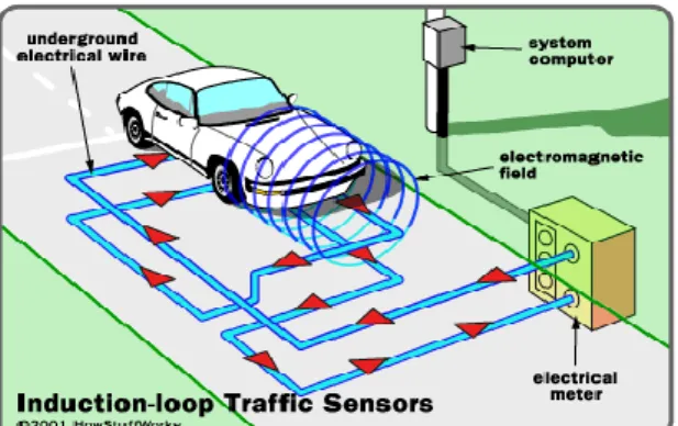
a) Induction Loop Traffic Sensors[8]
Inductive loop detectors (ILD) consist of one or more loops of wires placed inside the road and all these loops are connected to a control box, which is connected by a signal ranging in frequency from 10 KHz to 200 KHz. Whenever a vehicle moves over or stands on the loop, the inductance of the loop is reduced showing the presence of a vehicle. The data generated by detectors are vehicle passage, presence, count, and occupancy. For incident detection, loop data is usually relayed to a centralized transportation management center for analysis with a computer based Automatic Incident Detection algorithm. These are capable of measuring flow and occupancy, and estimating vehicle speed. They can also be used to actuate traffic control devices and detect congestion and incidents. These detectors may suffer from poor reliability mostly due to improper installation and have high life-cycle costs. In some locations they are not the most appropriate detectors, for example when pavement conditions are unfavorable, on structures or where detection is needed across railway tracks.[3]
It simply works on induction principle. Iron core (car) passing through a coil (simple wire) produces large inductance when compared to air.
Figure 1: Induction –Loop Traffic Sensors Benefits of Inductive Loop Detectors:
The benefits of inductive loop detectors are
Inductive Loop Detectors continues to be the best in all weather, all light conditions of sensor for many applications.
Inductive Loop Detectors works in similar manner both high and low volume traffic.
ILDs meet even the most stringent vehicle flow error specifications required by some ITS application.
b) Wireless vehicle detector sensor systems:
Detectors are positioned where they will detect queues that are in danger of blocking upstream junctions and causing congestion to spread through the network. Within SCOOT, the traffic manager is able to prioritize where such problems should be minimized and SCOOT then automatically adjusts timings to manage the congestion.
Why should people wait for a red signal if there is no traffic that is how it leads to rule breaking? Every time there is a jam at a particular crossing, someone goes and analyzes the pressure of vehicles and adjusts the signals times manually.
c) Pneumatic Road Tubes [9]
Pneumatic road tube technology uses rubber tubes placed across traffic lanes in a specific configuration. When a pair of wheels (on one axle) hits the tube, air pressure in the compressed tube activates a recording device that notes the time of the event. Based on the pattern of these times (for instance, the length of the interval between the time that two axles of a typical vehicle activate the counter), the device will match each compression event to a particular vehicle according to a vehicle classification scheme. Two tubes attached to the same counter can be placed a set distance apart in order to determine speed by measuring the interval between the time an axle hits the first tube and the time it hits the second tube. [4]
Volume 5, Issue 7, July 2016
2479
d) Images and Videos: Images and Videos are camera
based detection which surveillance cameras monitor traffic states and detects the congestions other incidents that are occurring on the roads, based on various computer vision Techniques used for Traffic Controlling.
e) Acoustic Sensors: Acoustic Sensors now –a –days using
in the lanes of developing countries for estimating the traffic in the lane where the traffic is busy and Noisy.
f) RF sensors: RF Sensors are Wireless Radios that are
placed across the road have communication signals affected by vehicular movements in between which are used to monitor the status of the vehicles on the roads.
Mobile Sensing Techniques:
(1) GPS on public transport or fleet vehicles – Many
public transport and fleet companies have GPS installed in their vehicles for real time tracking through which one can count the total number of vehicles in the lane.
(2) GPS on smart phones: With the recent growth of
Smart phones, the GPS in Smart Phones is using now a day to estimate travel time after handling noise in GPS readings.
(3) Using Ordinary Phones: Ordinary phones are used for
traffic sensing through sensing the localization of the current cellular tower and Wi-Fi information they are currently on their phone.
Hybrid Sensing Techniques: There are a set of techniques that use both static
infrastructure and mobile sensors to gain traffic information.
a) Tele density: Tele density Refers to the density of
mobile phones (nodes) that are connected to a network tower in that region through which the service provider can provide an approximate value of number of vehicles on the road.
b) Bluetooth: Bluetooth devices are placed on the
road side which are able to detect and communicate with the Bluetooth devices that are present in the car On Board Units or the mobile phone user in the cars, the roadside units senses and gives travel times of the vehicles between the detectors and maintains a separate tables for every address that connects.
c) RFID :Vehicles are also can be detected by using
RFID Tags placing on the vehicles and the RFID
Tag Readers are placed on the intersection points for detections of vehicles and for counting the number of the vehicles.
d) Similar systems2 are being explored using RFID
tags on vehicles and RFID readers on roads.
II. Types of data measured: These may include time
of arrival, speed, and axle spacing (vehicle type).
III. The positioning of the devices used: This would
involve investigating the distance for advance detection, number of detector to be used and use of detector arrays.
Prediction: Prediction is the process by which the data
detected from the detector are used to determine the arrival pattern of the vehicles to be used by the adaptive control system. The system cannot process vehicles in reality it can make the determination for vehicles over a given time horizon. Prediction creates a pattern of vehicles over the time horizon in the control.
The prediction includes the following issues:
I. Length of time horizon to be used: This may be as
short as a minimum vehicle headway (e.g. 2 seconds) and may be considered as a given cycle length, a 15-minute interval, a peak periods, or may be left variable.
II. Use of Multiple time horizons: The Horizons may
have different lengths, and may be used for different purposes, such as decision thresholds and detection intervals.
III. Process by which pattern is generated: This is a
process replicating a old detected pattern, scaling a historical pattern, fitting a probability distribution, or using a time-series model.
Optimization: Optimization is the process by which the
predicted vehicles arrivals are used to distribute green times to the various approaches of the intersection. It also optimizes a measure of effectiveness based on the vehicle arrivals.
Optimization includes the following
I. Measure of Effectiveness to be used: This is
based on the number of vehicles and the type of user.
II. Objective Function: Objective Function is a
mathematical Function that will determine the impact the vehicle arrival patterns have on the
Volume 5, Issue 7, July 2016
2480 measure of effectiveness and the green time will be
distributed.
Differences between fixed-time planning traffic control system and ATCS
In India all most all Traffic Control Systems works on the fixed time basis, where a timing plans are predefined these fixed time systems having a problem that they cannot adopt the traffic conditions so that even a lane is filled with traffic and other lane is not filled with the traffic sometimes it may give the green even there is no traffic in the lane, this increases the waiting time and consumption of fuel is more. Whereas the adaptive traffic control systems will adapts the current traffic condition and it gives signals accordingly which improves economy of the country in terms of fuel and time.
Different Types of Adaptive Traffic Signaling Systems
[5][10]
SCATS
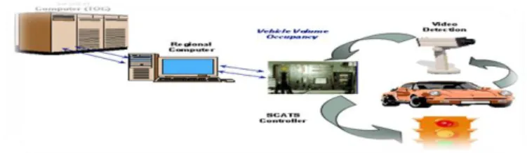
SCATS is a acronym of “Sydney Coordinated Adaptive Traffic System”, is an intelligent computerized traffic management System developed maintained by roads and maritime services (RMS) in Sydney. The System has been used in Melbourne since 1982 and in Western Australia since 1983. After positive Results in implementations some other countries also applied it their cities to get rid of traffic problems examples where they are implemented are Tehran, New Zealand, Shanghai, Amman, Dublin, Oakland County, Minneapolis and Michigan. As of February 2012, SCATS deployed in 258 cities of 26 countries worldwide controlling more than 34,943 intersections ,installations are done in Australia, Bangladesh, Brazil, Brunei, Chile, China, Ecuador, Fiji, Indonesia, Iran, Ireland, Israel, Jordan, Laos, Malaysia, Mexico, New Zealand, Philippines, Poland, Qatar, Singapore, South Africa, Thailand, USA and Vietnam. SCATS collect data from various intersections. Data is stored in the central computer with the traffic controller .The computer controls the traffic signals basing on frequently changing the traffic flow at each intersection .The adaptive traffic control system helps us to minimize stops(light traffic),delay (Heavy Traffic) and travel time by selecting the most appropriate cycle length, splits and links (or offsets).
SCATS is a two level operated system namely upper level and lower level, upper level involves the offset plan selection and the lower level which involves optimizing the junction parameters of the lane. Upper level generates offset plans by time of the day from historic data and lower level
optimizes the green signal
cycle times and offsets between signalized junctions using an incremental feedback process based largely on detectors situated at the stop lines. SCATS calculate the green splits based on the flow in the previous cycle and so is not fully responsive to unpredictable arrival flows. SCATS characterized by the network manager have a more direct involvement than other systems in setting up the system. In others SCATS can be defined as the System that detects the traffic volume by movement and converts data into flow rate then it calculates the optimal cycle length and split by phase and determines phase combinations.
Figure 3: Working of a SCATS System
Benefits and Advantages of SCATS
The SCATS System is being selected by various countries for the following benefits system architecture is simple to implement.
I. I. Better handling of traffic patterns and volumes, also capable of in special days where a sure dynamic control is required.
II. Reduced air pollution, fuel consumption, delay.
III. These systems are capable of handling long pedestrian clearance.
To detect equipment malfunction the system uses the effective maintenance alarm system.
2. SCOOT
SCOOT is an acronym of “Split cycle Offset Optimization Technique” was developed with the collaboration of Transport Research Laboratory (TRL) and UK Traffic Systems Suppliers Peak Traffic Ltd. SCOOT is toll very well known for managing traffic on signalized road
Volume 5, Issue 7, July 2016
2481 networks. SCOOT is implemented over 130 towns and cities
in the UK and overseas Worldwide.
The process of SCOOT can be simplified in few main tasks .It is a complete and adaptive traffic control system, therefore it gathers data and information that vehicle detectors record and then processes this information to optimize the traffic signal and reduce stops and delays. Over time Reduction in vehicle delays, congestions and providing many traffic management facilities are just a few options that SCOOT can provide. For instance, an excellent facility was introduced in 1995 to integrate active priority to buses, connected with bus priority, by the SCOOT urban traffic control system. The system was designed to detect buses either by selective vehicle detectors or by an automatic vehicle location (AVL) system.
Any Adaptive traffic Controlling System depends on good detection techniques for a quick response from the system .SCOOT has a database for storing, manipulating and presenting traffic data including flows, journey times and queues. It has three optimization procedures by which it adjusts signal timings these are the cycle time, green splits, and offsets, each optimized using a different procedure at different frequencies.
Benefits and Advantages of SCOOT
SCOOT has been enhanced, particularly to offer an ever wider range of traffic management tools. The traffic manager has many tools available within SCOOT to manage traffic and meet local policy objectives SCOOT detectors are positioned where they will detect queues that are in danger of blocking pstream junctions and causing congestion to spread through the network SCOOT will continuously monitor the sensitive area and smoothly impose restraint to hold traffic in specified areas when necessary.
SCOOT naturally reduces vehicle emissions by reducing delays and congestion within the network. In addition it can be set to adjust the optimization of the signal timings to minimize emissions and also provide estimations of harmful emissions within the controlled area.
SCOOT makes about 10,000 decisions per hour for every 100 intersection in the system all made by central computer.
3. ITACA
ITACA is a acronym of Intelligent Traffic Area Control Agent is comprised of a adaptive subsystem that operates
with a traffic model and produces cycle split and offset times for a centralized area of traffic control where these times minimize delay and stops of traffic moving in the area of traffic control. ITACA provides best real time urban traffic control by computing the best solution for every intersection and continuously adapts signaling to match the current demand. The system produces small and frequent changes in traffic control parameters that smoothly adapt the traffic control plan to evolving changes in traffic demand. This system is based on the coil real-time collection data, in the computer module the simulation real-time optimization movement
ITACA is an integral solution for traffic management in urban areas, providing the capability to control traffic intelligently in real-time, while constantly adapting to changing traffic needs. ITACA updates every 5 seconds on carry on a time of collection and processing to the transportation data. Currently 128 junctions are installed with ITACA in putrajaya and all are fully operational and some are in flashing amber.
Benefits and Advantages of ITACA
ITACA is auto adapted traffic control system.
ITACA is based on the real-time collection and quickly adapts traffic and produces green timing.
4. UTOPIA
UTOPIA is an acronym of Urban Traffic Optimization by Integrated Automation/SPOT (System for Priority and Optimization of Traffic) is the world’s most advanced adaptive traffic control system .The main aim of UTOPIA is to minimize the total time lost by private vehicles at the traffic intersections. The optimization is carried out at two levels: local and network. At the local level, the controller determines the signal settings by optimizing a cost function adapted to the current intersection traffic situation. It ensures that optimal traffic control strategies are applied during all traffic. UTOPIA-SPOT is an UTC system that produces co-ordination within an area without neither a common nor a fixed cycle time for each intersection. UTOPIA Spot is installed in major cities in Scandinavia, such as Oslo, Trondheim, Copenhagen and it is now used in several cities in Italy and also in the Netherlands, USA, Norway, Finland and Denmark.
UTOPIA offers a wide range of strategies designed to suit any road network .In fully adaptive mode it constantly
Volume 5, Issue 7, July 2016
2482 monitors and forecasts the traffic status and optimizes the
control strategy according to flow efficiency and/or environmental criteria. This gives high performance even with unpredictable traffic conditions.
Finally UTOPIA is a prediction based strategy that eliminates how the traffic situation will and calculates best strategy for controlling the traffic. Best strategy refers to the cost function; the cost function weighs the issuers of delays, fuel wastage.
Benefits and Advantages of UTOPIA
The following are the benefits and advantages of UTOPIA UTOPIA is a fully adaptive traffic controlling System, adjusts to the traffic situation.
UTOPIA realizes strategic traffic policy objectives.
UTOPIA is a dynamic priority levels for public transport vehicles.
UTOPIA is tuned and tested in lab situation before installation on-site.
UTOPIA follows Open communication infrastructure.
Advantages and Disadvantages of the Systems
Advantages
These systems are helpful in reducing stops, delays and emissions compared to pre timed systems and these systems doesn’t require any periodic update of timing plans.
Disadvantages
For establishing these type of systems initially it costs more and it incurs high maintenance cost for field components.
Maintenance Staff and Trained Operators are required.[5]
VANET based Adaptive Traffic Control Systems
VANET based Adaptive Traffic Control System is a Traffic Control System that works with Vehicular Adhoc Networking Technique in which the vehicles in the traffic are treated as the mobile nodes. VANET is a technology used to collect and aggregate real-time speed and position information on individual vehicles to optimize signal control at traffic intersections. VANET Environment Consists of
vehicles known as Mobile nodes which are in mobility in the direction of moving every time, Road side Units which acts as Hubs for Communications by extending the communication in the range which is placed on the Road and it allows to connect with OBU in the vehicle, On Board Units in the Vehicles are the Mobile Devices which are used for communication (acts as a transmitter and Receiver) in the Adhoc Network. In VANET based Adaptive traffic Control System the data is collected from the vehicles which includes the vehicle position and speed then utilizes the information to optimize the traffic signal scheduling at the interaction .This is enabled by onboard sensors in vehicles and standard wireless communication protocols specifically used in Vehicular Adhoc Networks.
This Adaptive Traffic Control System is based on the density of the vehicles, the number of vehicles that grouped into clusters is computed using a clustering algorithm and the calculated numbers of vehicles are sent to the traffic signals to set timing cycle. The Traffic Signaling System is based on car2car communication It reduces the waiting of the vehicles at intersection along with reduction in the queue of the length to realize the development of the system concept of clustering is used for the vehicles approaching the intersection. Different issues that are to be taken into consideration when designing the systems are to minimize the average delay time of the vehicles approaching an intersection, increasing progression by
coordinating vehicle platoons (platoons is a method of increasing the capacity of roads which they decrease the distance between cars or trucks) between intersections reducing the queue length of the all approaches to an intersection and even reducing overall fuel consumption and pollutant emissions.
To build a effective adaptive traffic Control System the system must calculate the effective of the intersections is control delay which is the component of vehicles delay caused by the presence of the signal control.
It is calculated in comparison with the travel time measured in absence of control mechanism .volume per capacity ratio reflects the degree of saturation at intersection, for saturated intersections the degree of saturation is calculated through the demand per capacity ratio which is
Volume 5, Issue 7, July 2016
2483 Minimizing the delay at the intersections helps in the
selection of cycle length as short as possible in order to produce less red time signal and to make shorter waiting queues. The perception here is that the cycle length should be decreased until a critical value is reached a value under which the overhead of phase changing starts to significantly influence the delay. According to the Webster Equation the optimum cycle length can be approximated with as a function of lost times and critical flow ratios.
C0=
𝟏.𝟓.𝐋+𝟓 𝟏−𝟏/𝐗𝐜 𝑽/𝐒𝒏𝟏 (1)
C0 is the optimum cycle length.
L is the sum of lost of all times for all the phases (yellow
and all-red times).
n is the number of critical lane groups.
A critical lane group is group of movements that can access the intersection concurrently.
Vi/Si is the maximum flow ratio for the critical lane group i.
1 /Xc is the desired degree of intersection utilization (1.0
for operation at full capacity, usually 0.95)
According to the Webster Equation the optimum cycle length can be approximated with as a function of lost times and critical flow ratio. Minimizing the delay at intersections suggests the selection a cycle length as short as possible in order to produce less red time and shorter queues. The perception here is that the cycle length should be shortened until a critical value is reached.
Different Intelligent Transportation System Techniques helps in the Following ways
Intersection Control: Controlling and deciding the signal cycle timing and split of green times among different lanes.
Incident Detection: Finding the Location of accidents or breakdown of a vehicle to respond in emergency Situations by which clearing the traffic will clear the congestion in the lanes.
Vehicle Classification: Classifying the vehicle arrival on the lane and based on the type of vehicle green timer will be issued.
Historical Data: Basing on the past data collected from various detection techniques are used for
analysis of the traffic situations and creating plan form green light timing at normal timings.
India’s transport sector is large and diverse it caters to the needs of 1.1 billion people. India has one of the most dense road networks in the world, with a total road length spanning more than 3.3 million kilometer. At the same time, traffic volumes have been steadily increasing over recent years due to increase in the Cars and SUVs in India and is projected to increase by 13-fold by 2035 w.r.t. the 2005 statistics. Increase in the vehicles causing various challenges such as increase in travel time, congestion, accidents, air and noise pollution, energy wastage etc. The recent surveys projected to vehicle s. Also the two-wheelers are projected to dominate with 70% of the vehicle population. The growths in the vehicles are growing drastically but the roads are not increasing at the same pace, due to the lack of space and hence causing congestion.
Many approaches to solve the issue of congested roads been tried – this includes building more roads, creating high occupancy vehicle (HOV) lanes, promoting car-pooling and public transportation - none has achieved more than modest success. For solving these issues the one alternative solution is to use Intelligent Transportation System. Advancement in intelligent transportation systems (ITS) is playing a valuable role in this regard. Through the ability to bring together system users, vehicles and infrastructure into one integrated system.
The paper focuses on the Adaptive traffic control signal system using VANET (Vehicular Ad-hoc network) and its applications. VANET enables vehicle-to-vehicle and vehicle–to-infrastructure communication and hence through communicating the relevant information it enables smooth traffic management.
VANET is being used in various application like Vehicle to vehicle (V2V) communication, Vehicle to infrastructure (V2I) communication, Real time traffic information systems, and cooperative message transfer, adaptive traffic control system which enables efficient and smooth movement of traffic on the roads.
Adaptive traffic control system is one of the important application of the VANET , where the signaling system automatically control the signals with respect to the number of vehicles present at that particular signal and hence reduces the waiting time at the traffic signal. Currently, this
Volume 5, Issue 7, July 2016
2484 system is not implemented. in India. This paper studied and
compared various options implemented and installed in various countries globally. The paper also broadly suggests the best option for implementation of ATC in India.
Proposed System for India
There are various options available for ATC like - SCOOT, SCATS, UTHOPIA, ITACA. These are implemented in various countries like UK, USA, Europe, and Japan. However it was found that some methods like inductive loop, implemented in countries like JAPAN, USA, UK . To install inductive loop for vehicle detection, we need to reconstruct the roads and is an expensive and time consuming. And hence may not be a suitable option for India due to its high cost and time.
Wireless Sensor Network is another option to count the number of vehicle per km of road as it is economic and scalable system. But at the same time it requires a large number of sensors as well as regular maintenance. The drawback in this system is failure due to battery drain, bad linkages, low level of security cost of the system, regular maintenance, range of the network etc.
Crowd sourcing is another emerging trend for the detection
of vehicles and can also address the issues of wireless sensor networks, it works similar to sensor based detections. Crowd sourcing becoming popular because of large growth in data enabled and location-aware hand held devices. These crowd sensed data overcome a number of issues with traditional physical sensor networks by providing wider coverage, real-time data and cost effectiveness etc.[6].According to Internet and Mobile Association of India (IAMAI), the growth of mobile phone internet users by 2019 is expected to rise to 813.2 million[7].
In India with the increase in the number of smart phone users as well as the increase in the number of Electronic control units in the vehicle, making the vehicles more and more intelligent, the growth rate of mobile Internet usage is increased drastically in India and the growth will be tripled by 2019.
These smart phone intelligent vehicle can be used to provide information about the location of the vehicle, current speed of the vehicle which then will be used to analyze the traffic condition on that patch of the road Crowd sourcing is a participatory networks and works based on the shared
networks where the users smart phones / vehicle serves a node in the network to replace traditional traffic sensor networks.
The data collected from the user, is stored and analyzed by the servers and the filtered data is disseminated to the user. The stored data is analyzed by using various big data predictive algorithms as well as vehicle optimization technique to predict and analyze the current traffic and the future traffic conditions which helps in distributing the green times to the various intersections. This can be done using fewer infrastructures. Hence in case of using crowd sourcing , the network available for the smart phones/ intelligent vehicles can be used for getting the real time traffic information system which then can be analyzed , filtered and send back to the users.
Crowd Sourcing is an new emerging technology of internet-of-things applications, uses sensors and computing power in mobile devices to sense the environment. The electronic devices like Mobiles, RSU, sensors are used for sensing the locations and able to aggregate various parameters of the traffic and these are stored in cloud service providers for storage and analysis.
Crowd Sourcing and Cloud Computing: According to the
Internet and Mobile Association of India (IAMAI) and Mobile Millennium projects suggests that a 2%-3% usage of smart phones by the drivers is enough to measure the accurate traffic conditions. Smart phones carried out the motorists periodically forward data like mobile Device Id, location Id ,Speed and Direction) to the cloud by the mobile network.
Methodology
Service Process: The following figure shows the logic
flowchart of a crowd sourcing traffic congestion control algorithm.
Volume 5, Issue 7, July 2016
2485
Figure 4: Flow Chart of Service Process of Crowd Sourcing
The motorists can get the traffic data from various mobile terminals like smart phones, Personal device assistants, on board units or sensors in the vehicles. If a request is sent from the motorist terminal then the system will reply the equivalent information. The following is the Crowd Control algorithm for system how it works
input: T: Time;
sd : The destination station Begin
Set the weight parameters α,βand γ;
Construct all values of di,j and qi,j according to the distances among stations;
Tc←current time; Tl←Tc;
while conditions are satisfied do if (Tc- Tl≥T) then
Construct the weight W using Equations (3) and (4); Get the next station snext;
Obtain and report the shortest path from snext to sd using Dijkstra’s algorithm; Tc←current time; Tl←Tc else Tc←current time; endif Endwhile end.
Algorithm 1: Crowd Control Algorithm
Let us consider the network into consideration has N stations, s1, s2, …, sN. The stations are usually deployed at intersections or junctions.R (si, sj) represents road segment from station si to station sj. The distance between si and sj is denoted by di,j, which remains constant after the corresponding stations have been deployed. The variable qi,j is used to express the quality of the road, the value which lies in [0,1]. We set the value as follows:
The quality values of roads R(s1, s2), R(s2, s3) are 0.5 and 0, respectively. The variable ri,j is used to express the existence of an event that causes congestion. We call such an event an adverse event; a collision is typical such event. The value of ri,j is assigned as follows:
ri,j={+∞, an adverse event has taken place, ( 0, otherwise.)} (2)
The average road speed vi,j is derived in the traditional manner, i.e., by dividing the distance di,j from stations1 to station s2 by the vehicle travel time. This method is simple, but does not consider vehicle parking. If the driver goes shopping and the vehicle parks in a parking lot between station s1 and station s2, the shopping time is accumulated with the travel time, so the value of vi,j is inaccurate.
In algorithm, we assumed to obtain the real-time speed using speedometer measurements in a specific period T. If the vehicle is located on the road, which can be verified using a GPS receiver and map matching software, we consider the speed value to be qualified at that moment. The average speed vi,j is the expectation of all qualified real-time speed values. It is underlined that, when the vehicle does not lie on a given road, the corresponding real-time speed value must be discarded. In the above-mentioned situation, speed measurements during shopping time should be discarded.
qi,j = 0, R(si,sj) is a first class highway; 0.5 R(si,sj) is a second class highway; 1, R(si,sj) is a third class highway; +∞, R(si,sj) cannot be used. (1)
Volume 5, Issue 7, July 2016
2486 Subsequently, we construct a weighted directed graph G =
(V, E, φ) as follows. Let V = (s1, s2, …, sN), and E = (si, sj) there exists a direct path between s1 and sj}, and φ be a function: E→R+ such that:
φ(si,sj)=αvi,j−−−√+βdi,j+γqi,j+ri,j (3) Where α,β,γ are the prescribed weights, and φ(si,sj) is assigned to be +∞ if the value of vi,j is detected to be zero. We then obtain a weighting matrix WN × N such that:
Wi,j=φ(si,sj) (4)
If we want to obtain a path plan to the destination from any given location, we need to reach the next stationsnext first. Then, we obtain a routing from the station snext to the destination sd. Also, we may form an updated version of the path within a given period T. In other words, we obtain a new path every T seconds.
In order to reach this goal, we first set the
parameters α,β,γ, the period T, the destination station sd, the distances and the road quality between stations. Then together with the information about vehicle speeds and events between stations, which is obtained from the cloud server, we obtain a weighting matrix W for the paths between stations and thus we form a directed weighted traffic network. Now, when asked to give the optimum path to a destination sd, we first reach the next station snext and compute the desired path from snextto sd.
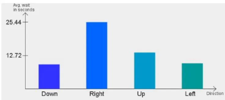
The algorithm calculates the average waiting time at every signal point and and alerts the vehicle to choose the lane and whenever the vehicle reaches the signal it will automatically start sending vehicles based on the strength of the vehicles at every intersection point or junction in the lane.
Figure 5: Average waiting time of vehicle at various junctions
Conclusion
In case of India crowd sourcing can be one of the best options for Adaptive traffic control system. Since through the use of crowd sourcing, real time traffic information can
be collected with few infrastructure. Also it requires low maintenance and is cost effective system also.
In recent years, the emerging technologies (e.g., mobile cloud computing) together with the improvement of the infrastructure have brought new opportunities for traffic prediction and congestion alleviation. In this paper, we focus on reliable traffic prediction approaches and various types of adaptive traffic control algorithms. we propose a mobile crowd sensing technology to support dynamic route choices for drivers to avoid congestion. We believe that traffic prediction through crowd and cloud-assisted will attract enormous attention and research efforts in the near future.
Future Scope
The Research in the Adaptive Traffic Control Technology is improving now-a-days to improve the safety and security for traveler, to provide various traffic related information and to reduce various problems that are causing by the rapid growth of vehicles. The major problems are accidents, congestion. In order to reduce these problems various researches are undergoing on Adaptive traffic Control system based Technologies. According to various researchers point reduction in congestion will reduce the accidents.
References
1. Development of a Phase-by-Phase, Arrival-Based, Delay-Optimized Adaptive Traffic Signal Control Methodology with Meta heuristic Search
2. Rijurekha Sen, Bhaskaran Raman. Intelliegnt Transportation System for indian cities.
3. trafficsensors.html,Howstuffworks/workingofinduction-loop.
4. Sanderson, Patrick McGowen and Michael. Accuracy of Pneumatic Road Tube Counters.
5. Talib, Prof. Ir. Dr. Riza Atiq Abdullah and Mohamad Jaffa. Urban Traffic Management System.
6. Vehicular communication: a survey. Sourav Kumar Bhoi, Pabitra Mohan Khilar.
7. http://www.statista.com/statistics/274658/forecast-of-mobile-phone-users-in-india/
8. Trafficsensors.html, Howstuffworks/workingofinduction-loop.
9. Sanderson, Patrick McGowen and Michael. Accuracy of Pneumatic Road Tube Counters.
10. Talib, Prof. Ir. Dr. Riza Atiq Abdullah and Mohamad Jaffa. Urban Traffic Management System.
11. http://ops.fhwa.dot.gov/publications/fhwahop06006/chap ter_8.htm.
Volume 5, Issue 7, July 2016
2487
12. Vehicular communication: a survey. Sourav Kumar Bhoi, Pabitra Mohan Khilar.
13. http://www.statista.com/statistics/274658/forecast-of- mobile-phone-users-in- india/http://www.statista.com/statistics/274658/forecast-of-mobile-phone-users-in-india/. 14. http://www.business- standard.com/article/management/mobile-phone-growth- shaping-india-s-internet-usage-greatly-116022800599_1.html.
15. AsifRehan. Information, Crowdsourcing Real-Time Traveler.
16. M. Shahid Anwer University of Reading, UK,. A Survey of VANET Technologies. 2014.