Fuzzy based DC Voltage Controller for High Power
STATCOM with Asymmetric Twin Converter
S
AGARP
URIPANDA1, G. V. P
HANINDRA21
PG Scholar, Dept of EEE, Avanthi Institute of Engineering and Technology, Cherukupally, Vizianagaram (Dt), AP, India.
2
Asst Prof, Dept of EEE, Avanthi Institute of Engineering and Technology, Cherukupally, Vizianagaram (Dt), AP, India.
ABSTRACT-- In this paper a twin converter bases high power STATCOM is presented. The proposed STATCOM is compared with the previously existing STATCOM. The DC voltage Control of the STATCOM is also discussed in the work. This reduces the number of independent dc capacitor voltages to be controlled and eliminates the flow of third-harmonic current through the transformer. The other commonly used multilevel topology, i.e., cascaded converter topology comprises several single-phase H-bridge/full-bridge converters, with separate dc links. The following are the two associated problems of this topology: 1) The size of the dc-link capacitor required is high because the instantaneous power involved with each module varies at twice the fundamental frequency and 2) regulating voltage across a large number of self-supported dc-link capacitors makes the controller design complex. In order to overcome this problem we are using the proposed Asymmetrical Twin converter based STATCOM for Improving Power Quality. A new language was developed to describe the fuzzy properties of reality, which are very difficult and sometime even impossible to be described using conventional methods. Fuzzy set theory has been widely used in the control area with some application to dc-to-dc converter system. A simple fuzzy logic control is built up by a group of rules based on the human knowledge of system behavior. Replacing PI controllers with FUZZY controllers can also be done for reducing the THD (Total Harmonic Distortion).
Index Terms— Fuzzy, DC-link capacitors, Power Quality,
Cascaded inverters, voltage source converter(VSC), Twin converter, Pulse width modulation (PWM), Static compensator (STATCOM).
I. INTRODUCTION
Multilevel voltage-source inverters provide a cost effective solution in the medium-voltage energy management market [1]. These converters have been widely applied to the chemical, oil, and liquefied natural gas (LNG) plants, water plants, marine propulsion, power generation, energy transmission, and power-quality devices [2]. Generally, multipulse-converter-based [4] and multilevel converter- based [5]–[8] solutions are used for high-power applications. A multipulse converter uses more than one voltage source converter (VSC), with common dc link, operating with nearly fundamental switching frequency, and the output of each module is connected in series[7]-[9] through the multipulse transformer. By adjusting the triggering pulses of different VSCs, specified total harmonic distortion (THD)
of the injected current is achieved with reduced switching losses as compared to that of single-VSC-based solution. The major drawback of this scheme is the high cost and complex structure of the bulky multipulse transformer. Cascaded multilevel inverters are based on a series connection of several single-phase inverters. This structure is capable of reaching medium output voltage levels using only standard low-voltage mature technology components. Typically, it is necessary to connect three to ten inverters in series to reach the required output voltage. In recent years, the number and variety of applications of Fuzzy Logic (FL) have increased significantly. The applications range from consumer products such as cameras, washing machines, camcorders, and microwave ovens to industrial process control, medical instrumentation, decision-support systems, and portfolio selection. These converters also feature a very high modularity degree because each inverter can be seen as a module with similar circuit topology, control structure, and modulation [6].THD without switching the semiconductor devices at high frequency. The two most commonly used schemes are the diode clamped and the cascaded converter topologies. The diode clamped multilevel topology is mostly restricted to a three-level configuration because of the complex layout of the diodes (which grows as the square of the number of levels) and the need for capacitor voltage balancing [5]. To address some of the aforementioned limitations in multilevel converters, a four-level open-ended-transformer-based multilevel converter, shown in Fig. 1, is proposed in [1]. This topology uses reduced number of components (12 controlled switches with the anti-parallel diodes) as compared to diode clamped topology (18 controlled switches with anti-parallel diodes plus 18 diodes) [5]. Moreover, in this case, the semiconductor switches are arranged as the VSC, which enables easier structural layout and reduced driver circuit complexity. Therefore, the standard VSC power modules [include six insulated-gate bipolar transistors (IGBTs) and their driver circuits in one package] can be used instead of discrete components. Moreover, this topology utilizes cascade connection of the three-phase VSCs, and hence size of the dc-link capacitor is less as compared to that in cascaded H-bridge multilevel converter.
Fig. 1. Open-ended-transformer-based four-level STATCOM
The open-ended transformer topology has the similar component layout with the twin converter topology, reported as in [24]. In the twin converter topology, dc-link voltages of both the VSCs are to be maintained equal. Multilevel inverters include an array [5] of power semiconductors and capacitor voltage sources, the output of which generate voltages with stepped waveforms. Commutation of switches permits addition of the capacitor voltages, which reach a high voltage at the output.
A split-capacitor arrangement is used in open ended transformer- based circuit in [14] which requires the voltage balancing of two capacitor banks in each VSC. Therefore a total of four dc capacitor voltages are to be regulated. This requires a complex controller and generates third-harmonics and dc currents.
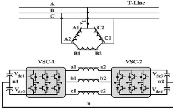
Fig. 2. Asymmetric-twin-converter-topology-based STATCOM
To address this limitation, an asymmetric twin converter topology is proposed in this paper wherein only two dc links are used without the split-capacitor arrangement, as shown in Fig. 2. Furthermore, THD of currents supplied to the grid is reduced by selecting a suitable ratio of dc-link voltages of two VSCs. A ratio of 1:0.366 is selected based on study of the open-ended induction motor drive, which has similar power circuit configuration as in [2]. Recently, many publications have addressed the multilevel converter technology and stressed the growing importance of multilevel converters for high-power
applications [4]–[9]. These works have a survey and tutorial nature and covers in depth traditional and well-established multilevel converter topologies.
II. ABOUT STATIC COMPENSATOR Modern power systems are very complex networks where hundreds of generating stations and many thousands of load centers are interconnected through a very long power transmission and distribution networks. The main concern of consumers is quality and reliability of power supplies at various load centers where they are located. Even though power generation in most well developed countries is fairly reliable.
Power distribution system should ideally provide their customers with an uninterrupted flow of energy at smooth sinusoidal voltage at a constant magnitude level and frequency. However in practice the power systems especially distribution systems have numerous nonlinear loads, which significantly affect quality of power supplied. A power quality problem is defined as any manifested problem in the voltage or current or leading to frequency deviations which result in failure or mis operation of the customer equipment. Depending on the electrical distance related to impedance, type of grounding and connection of transformers between faulted or load location and the node, there can be temporary loss of voltage or temporary voltage reduction (sag) or voltage rise (swell) at different nodes of the system. Voltage sag is defined as sudden reduction of supply voltage down from 90% to 10% of nominal, followed by a recovery after a very short period of time. A typical duration of a sag according to the standard is 10 ms to one minute .Voltage sag can cause loss of production in automated processes. Since voltage sag can trip a motor or cause its controller to malfunction. Voltage swell is defined as a sudden increase of supply voltage up 110% to 180% in rms voltage at the network fundamental frequency duration 10ms to one minute. Switching off a large inductive load or energizing a large capacitor bank in a typical system event causes swells. These devices are typically placed at the point of the common coupling (PCC) which is defined as point where the ownership of the network changes.
A.STRUCTURE
STATCOM (Static Compensator) schematically depicted in Figure 3, consists of two-level Voltage Source Converter (VSC), a dc energy storing device, a coupling transformer connected in shunt to distribution network through a coupling transformer. The VSC converts dc voltage across the storage device into set of three-phase ac output voltages. These voltages are in phase and coupled with ac system through reactance of the coupling
transformer. Suitable adjustment of the phase and magnitude of STATCOM output voltages allows effective control of the active and reactive power exchanges between the STATCOM and AC system. Such configuration allows device to absorb or generate the controllable active and the reactive power.
Fig.3. Schematic diagram of a STATCOM.
But, there are several factors that are to be considered when designing STATCOM and associated control circuits. In relation to the power circuit the following issues are of major importance:
DC link capacitor size
Coupling transformer reactance and transformation ratio
Output filters equipment
B. Principle of Operation
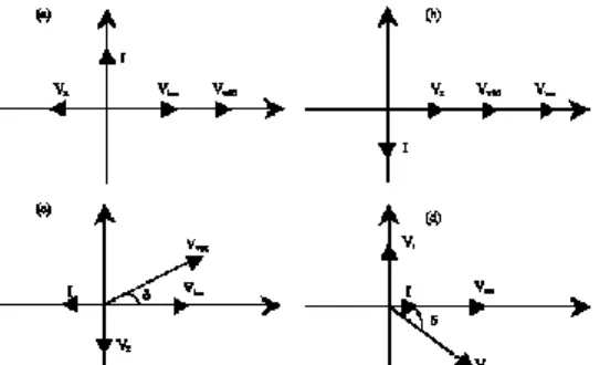
STATCOM is a device which is used to suppress voltage variation and control the reactive power in phase with system voltage. It can compensate for both the inductive and capacitive currents linearly and continuously. Fig.3.6 shows the vector diagram at the fundamental frequency for capacitive and inductive modes and for the transition states from capacitive to inductive and vice versa. The terminal voltage (Vbus) is equal to the sum of the inverter voltage (VVSC) and the voltage across the coupling transformer reactance VL in both capacitive and inductive modes. If VVSC is greater than Vbus and output voltage of STATCOM (VVSC) is in phase with bus terminal voltage (Vbus) ,then the STATCOM provides reactive power to system. And if VVSC is smaller than Vbus, STATCOM absorbs reactive power from power system. The little phase difference between Vbus and VVSC compensates the loss of transformer winding and inverter switching. This needs to absorb some real power from system.
Fig 4.Vector diagram of STATCOM (a) Capacitive mode, (b) Inductive mode, (c) Active power release and (d) Active power absorption
Fig.4. is STATCOM vector diagrams, which show inverter output voltage VI, system voltage VT, reactive voltage VL and line current I in correlation with magnitude and phase δ. Figure 4(a) and b explain how VI and VT produce capacitive or inductive power by controlling the magnitude of inverter output voltage VI in phase with each other.Figure4(c) and d show STATCOM produces or absorbs real power with VI and VT having phase±δ. The transition from inductive to capacitive mode occurs by changing angle δ from zero to a negative value.
C. Modeling of STATCOM
It is assumed that the source is a balanced, pure sinusoidal three-phase voltage supply with frequency ω. Since the reactive power compensation is desired by using this device, it is convenient for this analysis to take the angle of the input as the reference angle. However the system design is based on subsequent assumptions. 1. The three- phase AC mains voltages are balanced 2. The three - phase load is balanced and linear 3. The inverter switches are ideal
4. DC link output is ripple free
5. The filter components are reactive and linear
A single-phase equivalent circuit of STATCOM is shown in Fig. 5. Where, Rc is included to represent small losses in the switching devices of VSC. Rs and L represent the equivalent circuit of the tie-transformer between system voltages Us and the output voltage UI of STATCOM
III. PROPOSED MULTILEVEL CIRCUIT TOPOLOGY
A. Principle of Operation
The Asymmetric twin converter based multilevel topology comprises of two VSCs, is shown in Fig. 2. The Low voltage (LV) windings of the transformer are connected differentially between the two 2-level VSCs. It is connected in such a way that the voltage appearing on the LV side windings is the difference of the output voltages Vdc1 and Vdc2 of the two VSCs. High-voltage (HV) windings connected in a star configuration and connected to the three-phase grid supply. Leakage inductances of transformers act as an input filter inductances to the STATCOM. Both VSCs operate with separate dc links in order to produce a two-level individual output voltages. Voltages appearing on the LV side of the windings of the transformer can be written in terms of output voltages of the VSCs as follows
(1) where ea, ea1g1, ea2g2, and eg1g2 are the voltages across the LV winding of phase-a, the pole voltage of VSC-1, the pole voltage of VSC-2, and the voltage difference between negative dc-link terminals of the two VSCs, respectively. Since both VSCs have separate dc links, the sum of the LV winding phase currents should be zero
(2) Furthermore, the sum of instantaneous values of grid voltages is equal to zero
(3) The sum of the LV winding voltages is given by
(4)
Where r and L are the resistance and leakage inductance as Measured from the LV side, respectively and NLV/NHV is the turn‘s ratio. Substituting (2) and (3) into (4) gives
(5) Substituting LV voltages from (1) in (5) results in
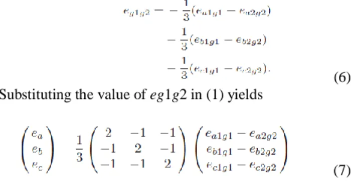
(6) Substituting the value of eg1g2 in (1) yields
(7)
The line voltages of the LV side eab, ebc, and eca are expressed as pole voltages using (1)
(8) For vdc2 = 0.5vdc1, depending on the state of switches, voltage waveforms of eab, ebc, and eca has seven different steps. This is same as the number of steps obtained in the line voltage of four-level diode clamped multilevel converter. For vdc2 = 0.366vdc1, nine different steps are observed in the line voltage waveforms, which is the same as that in four-level diode clamped converter with the capacitor voltage ratio vdc1 : vdc2 : vdc3 equal to 0.33:0.66:0.33. This makes the proposed scheme equivalent to a four-level converter.
B. PWM Strategy
The LV voltage ea takes one of the 25 values given by
Equation (7), depending on the state of switches. The switching states are decided by the modulating waveform and the PWM strategy used. Space vector modulation (SVM), Selective harmonic elimination method (SHEM), or the carrier-based PWM (CB-PWM) techniques are the
commonly used for high-power
applications.
‘
Fig 6 Comparison of modulating and carrier waveforms for PS CB-PWM.
SHEM is limited in use because of its slow dynamic response. Realization of the SVM for a multilevel converter requires a complex algorithm for identification of the sector. The presence of large number of sectors makes the implementation complex and almost
impossible [13]. Therefore, the use of the phase-shifted (PS) CB-PWM is suggested in this proposed topology. This PWM technique expects the controller to generate individual modulating waveforms for each of the inverter output ea1g1, eb1g1, ec1g1, ea2g2, eb2g2, and ec2g2. Each modulating waveform is then compared with a carrier waveform in order to determine the switching state of the corresponding inverter devices. This is similar to the PS CB-PWM technique used in the H-bridge cascaded converters. For the two H-bridges per phase, the resultant waveform of AC voltages is sum of the individual converter voltages. Therefore, the carrier waveforms are 180◦ PS from each other to cancel their carrier frequency harmonics. Though, in the case of asymmetric twin converter topology, the shift in carriers is not required because the resultant waveform is already the difference of two AC voltages. Comparison of modulating and carrier signals for phase-a is shown in Fig. 5.2. Modulated converter voltages ea1g1, ea2g2, and ea in the simulated case of Vdc1 = 805 V, Vdc2 = 294 V, fundamental frequency 50 Hz, carrier frequency fc = 900 Hz, and modulation index m = 0.9 are shown in Fig. 6. The absence of the lower order harmonics confirms the operation of PWM technique. Dominant harmonics are present at sideband of twice the carrier frequency. Although the sidebands of carrier frequency are also present, their magnitude is far less than that of twice the carrier frequency.
IV. DEVELOPMENT OF THE EQUIVALENT CIRCUIT OF THE SYSTEM
Fig.7.Equivalent circuit diagram of the proposed STATCOM.
For the purpose of analysis, an equivalent circuit of the proposed STATCOM is derived and is shown in Fig. 8. Transformer is represented by equivalent series combination of inductances, resistances, and voltage sources. To model the losses in two VSCs, two resistances r1 and r2 are placed in parallel to the two dc links. The governing equations of the proposed system can be derived as
(9) Where L is defined as ωbl/zbase. l, ωb, and zbase are the leakage inductance, base frequency, and base impedance of STATCOM. All the parameters and variables are
expressed in per-unit (p.u.) system. Equation (9) is transformed into dq0 reference frame, which has been defined in the Appendix. The system variables in the dq0 frame are expressed as follows:
(10) Where id and iq are the d- and q-axis components of LV-side currents. ed1 and eq1 are the voltage components of VSC-1, and ed2 and eq2 are the voltage components of VSC-2. Equation (10) interrelates the ac parameters of the STATCOM with those of the grid. The dependence between dc and ac parameters of STATCOM is derived using instantaneous power balance equations. The following equation gives the power balance condition between the ac and dc links of VSC-1:
(11) The current flowing through the dc-link capacitor c1 is related to the dc-link voltage vdc1 as follows:
(12) Where C1 is defined as 1/ (ωbc1zbase). Substituting idc1 From (11)
(13) Similarly, the governing equation for VSC-2 is expressed as
(14) Equations (10), (13), and (14) represent the behavior of the system.
V.FUZZY LOGIC CONTROL
L.A.Zadeh is the first person to present the paper on fuzzy set theory in 1965. Since then, a new language is developed in order to describe the fuzzy properties of reality. These properties are very difficult and sometime even impossible to be described using the conventional mathematical methods. Fuzzy control has emerged as one of the most active and promising control areas, as it can control systems which are highly nonlinear, time-variant and ill-defined system functions. Most of the modeling in In contrast with traditional PI controller‘s linear and nonlinear control theory, FLC is not based on any specific mathematical model but it is widely used to solve problems under uncertain and vague environments and with high nonlinearities. With the Fuzzy Logic Control
the design concept is totally different. Basic Fuzzy control systems are based on expert knowledge that can convert the human linguistic concepts to an automatic control strategy without any complex mathematical models. This control technique basically relies on the human capacity to realize the system‘s behavior. This determines the effectiveness of the linguistic rules of the Fuzzy Controllers. So, the design of Fuzzy logic controller can be provided on both small signal and large signal dynamic performance at the same time. This is not possible with linear control techniques. So, the Fuzzy Logic Controller has the potential ability to improve the robustness of converters.
The basic scheme of a fuzzy logic controller is shown in Fig 12 and consists of four principal components such as: a fuzzification interface, which converts input data into suitable linguistic values; a knowledge base, which consists of a data base with the necessary linguistic definitions and the control rule set; a decision-making logic which, simulating a human decision process, infer the fuzzy control action from the knowledge of the control rules and linguistic variable definitions; a de-fuzzification interface which yields non fuzzy control action from an inferred fuzzy control action [10].
Fig.12 Block diagram of the Fuzzy Logic Controller (FLC) for proposed converter.
Fig.13 Membership functions for Input, Change in input, Output.
Rule Base: the elements of this rule base table are determined based on the theory that in the transient state,
large errors need coarse control, which requires coarse in-put/output variables; in the steady state, small errors need fine control, which requires fine input/output variables. Based on this the elements of the rule table are obtained as shown in Table III, with ‗Vdc‘ and ‗Vdc-ref‘ as inputs
VI.MATLAB MODELING AND SIMULATION RESULTS
Here Simulation is carried out in two different Conditions, 1). Conventional Controller Based High Power STATCOM. 2). Intelligence Controller Based High Power STATCOM.
Case 1: Conventional Controller Based High Power STATCOM
Fig.11 Matlab/Simulink Model of Conventional Controller Based High Power STATCOM.
Fig.12 HV-side (grid) phase-a voltage & LV-side phase-a transformer current.
As above fig 11 show the Matlab/Simulink Model of Conventional Controller Asymmetric Twin Conversion
Based High Power STATCOM, Fig.12 shows the HV Side Phase A voltage and LV Side Phase A Transformer
current, with conventional
controller.
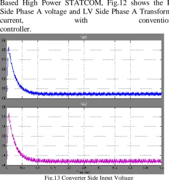
Fig.13 Converter Side Input Voltage
Fig.13 shows the Converter side input voltages, nothing but primary side voltages to support the converter operations with conventional controller.
Fig.14 FFT Analysis of LV Side Phase A Current
Fig.14 shows the FFT Analysis of LV Side Phase A Current, we get 4.19%, with conventional controller.
Case 2: Intelligence Controller Based High Power STATCOM
Fig.16 Converter Side Input Voltage
Fig.16 shows the Converter side input voltages, nothing but primary side voltages to support the converter operations with intelligence controller.
Fig. HV-side (grid) phase-a voltage & LV-side phase-a transformer current
Fig. shows the HV Side Phase A voltage and LV Side Phase A Transformer Current with Intelligence Controller.
Fig.18 FFT Analysis of LV Side Phase A Current
Fig.18 shows the FFT Analysis of LV Side Phase A Current, we get 1.02%, with Intelligence Controller.
VII. CONCLUSION
PI, PD and PID controllers are conventional, most popular controllers and widely used in most power system appliances. But, in the recent times there are many researchers who reported and successfully adopted Fuzzy Logic Controller (FLC) termed as intelligent controllers to their appliances. A high-power Asymmetric twin convertor based STATCOM consisting of two 2-level VSCs is proposed with two different controlling techniques .One stands to be with the conventional PI controller & the other being the Fuzzy Logic Controller (FLC) or the intelligence controller. Simpler layout of switches, reduced component count, and reduced capacitance requirement are among the best features of this scheme over the diode clamped and the cascaded multilevel converters. In the proposed topology, only two DC voltages have to be controlled in order to maintain the STATCOM as per the requirement. In addition, the ratio
of dc-link voltages of the two VSCs is selected in such a way that low distortion in current is achieved. A MATLAB simulation model of the system is developed to facilitate the design of the conventional PI controller & FLC (Fuzzy logic or intelligent controller). Detailed simulation studies prove that by using Intelligence controller (FLC) we get a better response and better THD values. In the Fuzzy based controller the Total harmonic distortion was reduced to a considerable amount of 1.02% compared to the conventional PI controller of 4.19%. This clearly justifies the implementation of Fuzzy Logic Controller (FLC) to be a breakthrough in the forth coming days.
.
REFERENCES
[1] S. Anand, B. G. Fernandes, and K. Chatterjee, ―A new 4-level open-ended transformer based STATCOM for high power applications,‖ in Proc. 36th Annu. IEEE IECON, Nov. 7–10, 2010, pp. 1957–1962. [2] C. Schauder and H. Mehta, ―Vector analysis and control of advanced static VAR compensators,‖ Proc. Inst. Elect. Eng. C—Gener., Transm. Distrib., vol. 140, no. 4, pp. 299–306, Jul. 1993.
[3 G.Satyanarayana., K.N.V Prasad, G.Ranjith Kumar, K. Lakshmi Ganesh, "Improvement of power quality by using hybrid fuzzy controlled based IPQC at various load conditions," Energy Efficient Technologies for Sustainability (ICEETS), 2013 International Conference on , vol., no., pp.1243,1250, 10-12 April 2013.
[4] D. Soto and T. C. Green, ―A comparison of high-power converter topologies for the implementation of FACTS controllers,‖ IEEE Trans. Ind. Electron., vol. 49, no. 5, pp. 1072–1080, Oct. 2002.
[5] K.N.V Prasad, G.Ranjith Kumar, T. Vamsee Kiran, G.Satyanarayana., "Comparison of different topologies of cascaded H-Bridge multilevel inverter," Computer Communication and Informatics (ICCCI), 2013 International Conference on , vol., no., pp.1,6, 4-6 Jan. 2013
[6] Y. Cheng, C. Qian, M. L. Crow, S. Pekarek, and S. Atcitty, ―A comparison of diode-clamped and cascaded multilevel converters for a STATCOM with energy storage,‖ IEEE Trans. Ind. Electron., vol. 53, no. 5, pp. 1512– 1521, Oct. 2006.
[7] H. Abu-Rub, J. Holtz, J. Rodriguez, and G. Baoming, ―Medium-voltage multilevel converters—State of the art, challenges, and requirements in industrial applications,‖ IEEE Trans. Ind. Electron., vol. 57, no. 8, pp. 2581–2596, Aug. 2010.
[8] S. Kouro, M. Malinowski, K. Gopakumar, J. Pou, L. G. Franquelo, B.Wu, J. Rodriguez, M. A. Pérez, and J. I. Leon, ―Recent advances and industrial applications of multilevel converters,‖ IEEE Trans. Ind. Electron., vol. 57, no. 8, pp. 2553–2580, Aug. 2010.
[9] F. Z. Peng, J. W. McKeever, and D. J. Adams, ―A power line conditioner using cascade multilevel inverters for distribution systems,‖ IEEE Trans. Ind. Appl., vol. 34, no. 6, pp. 1293–1298, Nov./Dec. 1998. [10] K. V. Patil, R. M. Mathur, J. Jiang, and S. H. Hosseini, ―Distribution system compensation using a new binary multilevel voltage source inverter,‖ IEEE Trans. Power Del., vol. 14, no. 2, pp. 459–464, Apr. 1999.
[11] C. K. Lee, S. Y. Ron Hui, and H. S. Chung, ―A 31-level cascade inverter for power applications,‖ IEEE Trans. Ind. Electron., vol. 49, no. 3, pp. 613–6, Jun. 2002.
[12] H. Akagi, S. Inoue, and T. Yoshii, ―Control and performance of a transformerless cascade PWM STATCOM with star configuration,‖ IEEE Trans. Ind. Appl., vol. 43, no. 4, pp. 1041–1049, Jul./Aug. 2007. [13] M. Malinowski, K. Gopakumar, J. Rodriguez, and M. A. Perez, ―A survey on cascaded multilevel inverters,‖ IEEE Trans. Ind. Electron., vol. 57, no. 7, pp. 2197–2206, Jul. 2010.
[14] Y. Fukuta and G. Venkataramanan, ―DC bus ripple minimization in cascaded H-bridge multilevel converters under staircase modulation,‖ in Proc. 37th IEEE IAS Annu. Meeting, 2002, vol. 3, pp. 1988–1993. [15] S. Vazquez, J. I. Leon, J. M. Carrasco, L. G. Franquelo, E. Galvan,
M. Reyes, J. A. Sanchez, and E. Dominguez, ―Analysis of the power balance in the cells of a multilevel cascaded H-bridge converter,‖ IEEE Trans. Ind. Electron., vol. 57, no. 7, pp. 2287–2296, Jul. 2010.
SAGAR PURIPANDA pursued B.Tech in
Electrical and Electronics Engineering In Raghu Engineering College Affiliated to JNTU Kakinada University. He is currently pursuing M.Tech in Power Electronics in Avanthi Institute of Engineering and Technology, Affiliated to JNTU Kakinada.
G.V.PHANINDRA pursued B.Tech. in Electrical and Electronics Engineering in BVC Engineering College and M.Tech in Power System control and Automation from G.V. P. College of Engineering. Presently he is working as Assistant professor in Avanthi Institute of Engineering and Technology. His areas of interest are Distribution Systems and Power systems.