Abstract— Project gives feasible solution to move and rotary
indexing the component with full proofing fixture for special purpose operations like drilling, Tapping, debarring, washing, drying involve in manufacturing and assembly. Rotary indexing type structure is made for handling the crank case inside the cleaning machine use for making fully ready component before assembly operation .System is useful to save time manpower and deliver perfect cleaned and dry component .system involved all the mechanical components along with the sensors used to restrict the rotating operations, stop and go operations etc. Mechanical structure and possible loading conditions are studied and calculated to validate the bending and deformation effects while it take indexing at different angle. Structure will rotate 360 degree with multiple stoppages and inside the structure cylinder block will be fixed automatically, stress values need to be calculated on multiple stoppages/ indexing angles.
Index Terms— Rotary indexing, Roller Wheel, Fixture,
Strain, Stress, Deformation.
INTRODUCTION
Design of automated Rotary indexing Type Fixture For crank case is taken from the special purpose machine in which component crank case) is to be machined, cleaned ,dry, and proceed towards assembly section in continuous production line of Automobile company The arrangement of said project will be process wise well defined sequence and operation for the decided cycle time where the rotary Fixture along with component will be get stoppage at every angular position with the used sensors .Operation cycle will be run through PLC Programme.
Problem Identification
Rotation of crank case is not possible manually; in automated drilling and other operations component need to be rotate indexing mode so that robotic drill can be face the drilling surface with precision. Rotary cage is to be made to give feasible solution .deformation may occur while rotation .stress may be increase at multiple angles as the load is coming directly on cage.
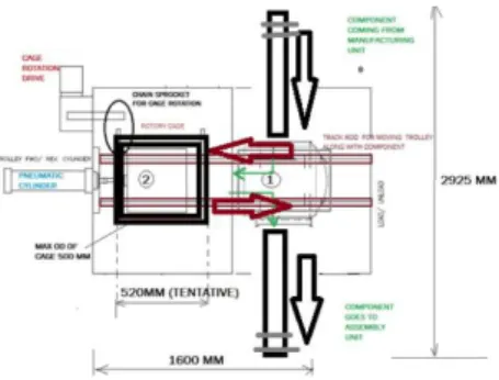
Fig. 1 Layout shows Need of indexing Present Theories and Practices
Without rotating component it can be operated by keeping operating face open toward tool it can be operated with only single process multiple processes can’t be handle simultaneously , since ,face wise operation can be changed. After operating with tools component need to be clean before reaching to assembly section again another station component is transfers by moving fixture, here manual handling and manual air blow for cleaning ,cavities, holes, oil, coolant, dirt etc. It takes more time to complete all these processes,
It will have been good if rotary indexing is provided in a single station with common fixturing with allowing face indexing only tools will change on same place and component will take rotation.
Fig. 2 Design of Existing Cage
Process optimization, design and analysis of
horizontal Indexing cage fixture
Vishal Kumar, Prof. Dr. S.G. Taji, Prof. Baban P. LondheShree Ramchandra College of Engineering, Lonikand, Pune, India MIT Academy of Engineering, Alandi, Pune, India Shree Ramchandra College of Engineering, Lonikand, Pune, India
Fig 3 Initial Cage Design Design Input :
• Total set of Fixtures Trolley required to be Mounted- 1Nos
• Total Weight Of components: 300 Kg • Maximum Available Area: 2Mtr x 3Mtr • Loading Height: 1000 mm from ground. • Degree of rotation for cage -360 degree • material for construction- AISI 304, non-metal
-UHMW
• 3D model of crank case
• Trolley Fixture model already available
• Indexing structure to be designed for this assembly.
Fig 4 Trolley
II. LITERATURE REVIEW
1) Thomas and Ghadhi
(1986) Worked on Fixtures which are important in both traditional manufacturing and modern flexible manufacturing system (FMS), which directly affect machining quality, productivity and cost of products. The time spent on designing and fabrication fixtures significantly contributes to the production cycle in improving current product and developing new products [5].
2)
2) Nee & Kumar (1991) also developed a rule-based
automated fixture design. In addition to the functionality offered by Nnaji et al. Nee & Kumar performed a limited check on the displacement likely at each locating point as a result of the machining forces and also implemented a simple justification module that employed heuristic rules to determine whether a modular (comprised from a set of standard components) or dedicated (custom) fixture design should be generated [6].
3) Jeng and Gill (1997) formulated a fixture design problem
in hierarchical design structure. Mervyn et al. (2003) presented an internet-enabled fixture design system by the use of XML file format. Rios et al. (2005) and Alarcon et al. (2010) developed and presented KBE (knowledge based engineering) application for, modular fixture design. Hunter et al. (2006) presented a functional design approach in which the functional requirements and constraints are considered as an input to the fixture design process. Taufif Bin Zakaria & Wang and Rong (2008) and Sun and Chen (2007) presented the case based reasoning method to provide a computer aided fixture design solution. Perremans (1996) developed an expert system for automatic fixture design [8].
4) Wu et al (1997) developed an automated customized
fixture design system. Based upon a fixture structure analysis, fixtures are divided into functional components (locators and clamps), fixture bases, and supports. The inputs to the approach are the work piece geometry together with the locating and clamping coordinates. A geometry-element generator generates fixture components with dimensions according to work piece geometry and operational information. Once individual locators and clamps have been designed individually, the support units can then be generated to connect the locators/clamps to the base plate, resulting in a complete fixture unit. Rules are used to select components [7].
III. DERIVED UNIT DESIGN & CALCULATIONS
Fig 5 Cage design followed by taking component dimensions for fitment
Material Data Grade Design strength (N/mm2) Ultimate tensile strength (N/mm2) Young's Modulus (N/mm2) Elongation (%) Stainless steel 304 210 520 200 000 25 316 220 520 200 000 22
Considering round cage as fixturing element to mount object fitted while rotating, Rotating parameters considering by full proof fitting of this heavy object.
Fig 6 Crank case easy mounting in cage
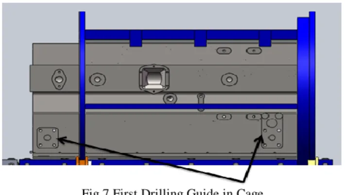
Fig 7 First Drilling Guide in Cage
Two locations are to be covered for drilling 8 numbers of holes.
Component is slide 100 mm left side to make opening for tool entering.
Fig 8 Second Drilling Guide in Cage
Drilling face is to be opened to make machined here in previous design
Drilling face was covering by cage plat, now its resolved by giving simple cut to the cage side.
Fig 9 Guiding wheel to hold cage fixture
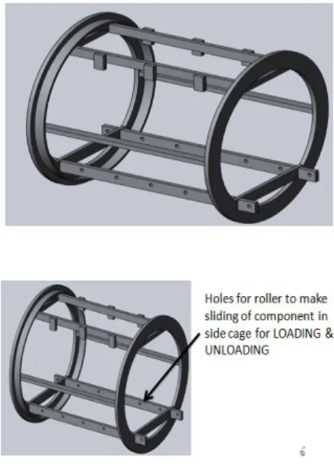
Fig 10 Bottom roller wheel for loading & unloading Multiple wheels will allow component to enter inside and unload by simple sliding by pushing and pulling operation by cylinder stroke
Drive unit made for the transmission of rotary motion into cage which is holding fixture cum component is made by considering the input parameters like speed and cycle time require for the process inside the machine.
Fig 11 Assembly of Driven unit
Calculations for selection and finalized the parameters: Total CAGE weight = 110 kg
Per component weight =300kg
For rolling applications, generally preferred value the coefficient of friction is 0.3.
Total pulling weight = Total cage weight
+ (Per component weight × Maximum
No. of components at a time) Hence,
1) Total pulling weight = 110 + (300×1) =410kg.
Maximum Pull = Total Pulling weight × Coefficient of Friction
= 410 × 0.3 =123 kg
= 1230 N ……… where, Consider g =10m/s2
2) For PCD of Drive sprocket, Chain pitch (P) = 25.4 mm
Number of teeth on sprockets (z) = 17 Time to travel pitch (t) = 60 sec.
Pitch Circle Diameter of Drive Sprocket, (PCD) = Pitch (P) / sin (180/z) (π/180)
Hence,
PCD of Sprocket = 25.4 / sin (180/17) (π/180) = 138.17 mm
= 0.138m
Since the driving sprocket is a ring bonded by chain of pitch 25.4 mm
Ring dia d =725 mm
Perimeter of ring =2 л d = 4553
No. of pitch will be on ring (z) = 4553 / 25.4 = 179.25 Chain pitch (P) = 25.4 mm
Number of teeth on drive sprockets (z) = 17 Pitch between rotation components (Pc) = 4553
mm(considered after every rotation fresh cycle) Time to travel pitch (t) = 60 sec.
3) Centre distance between two Shafts
= (PCD of Drive Sprocket + PCD of driven Ring) / 2 = (1384+725) /2
= 431.5 mm = 0.431 m
4) Torque Calculation For Drive Unit
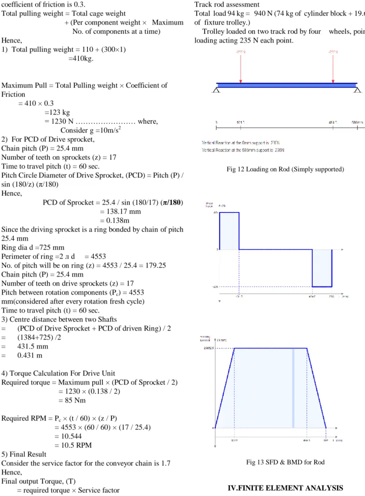
Required torque = Maximum pull × (PCD of Sprocket / 2) = 1230 × (0.138 / 2) = 85 Nm Required RPM = Pc × (t / 60) × (z / P) = 4553 × (60 / 60) × (17 / 25.4) = 10.544 = 10.5 RPM 5) Final Result
Consider the service factor for the conveyor chain is 1.7 Hence,
Final output Torque, (T)
= required torque × Service factor = 85 × 1.7 =144.5 Nm Final Output RPM, (n) = 10.5 rpm Final Output HP = (2 × л × n × T) / 45000 = (2 × л × 10.5 × 144.5) / 45000 = 0.212 HP Track rod assessment
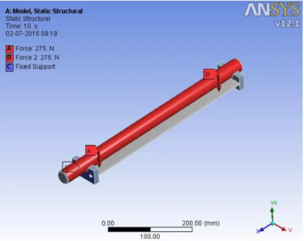
Total load 94 kg = 940 N (74 kg of cylinder block + 19.6 kg of fixture trolley.)
Trolley loaded on two track rod by four wheels, point loading acting 235 N each point.
Fig 12 Loading on Rod (Simply supported)
Fig 13 SFD & BMD for Rod
IV.FINITE ELEMENT ANALYSIS
The controls in this group set the basic size defaults for the initial mesh. Local controls (described later), can be used to override these values in specific regions of the model.
• These settings assume the “Use Advanced Size Function” is set to “Off”.
• Relevance Canter: sets the midpoint of the “Relevance” slider control.
• Element Size: defines element size used for the entire model.
• Initial Size seed: Initial mesh size is based either on the entire assembly or on each individual part.
• Smoothing: Attempts to improve element quality by moving nodes. Number of smoothing iterations can be controlled (Low, Medium and High).
• Transition: Controls the rate at which adjacent elements will grow (Slow, Fast).
Drum cage forming ring analysis
Fig 14 Force on Cage Ring
Fig 15 Elastic Strain on Cage Ring
Track Rod Weldment Assessment
Fig 17 Shear Stress on Rod
Fig 18 Equivalent Elastic Strain on Rod
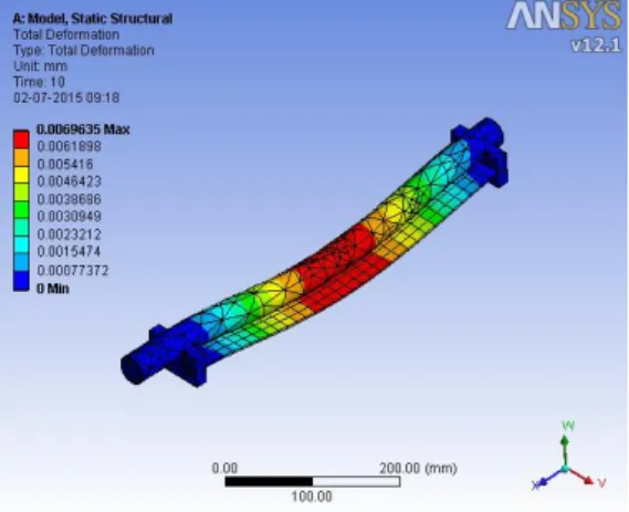
Fig 19 Deformation of Rod
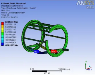
Fig 20 Directional Deformation on Rod
Stresses and deformation seen in the drum fixture structure: Loading distribution in drum rotor:
Total load 94 kg = 940 N
Fig 21 FBD of cage with external load
Fig 23 Deformation of Fixture
Fig 24 Strain of Fixture
Fig 25 Force on Fixture
Fig 26 Maximum Shear Stress
Fig 27 Directional Deformation
V. CONCLUSION
Total deformation 0.0214 mm found in drum as per FEA & But 0.02 mm found in physical validation, Stress level also 2.92 Mpa which reflect very safe working in structural behavior as per material
It has been concluded that round structured drum type horizontal fixture is possible to make indexing for heavy components in SPM.
Acknowledgment
It gives me great pleasure to submit my Dissertation on “Process optimization, design and analysis on horizontal Indexing cage fixture for cylinder block” to partial fulfillment of my ME Design Engineering. I take this opportunity to thank my Project guide Prof. Dr. S.G. Taji & Co-Guide Prof. Baban P. Londhe for his valuable guidance and his deep interest throughout the study and completion of the Project.
It would be befitting to mention a word of thanks to Prof. A.B. Verma, HOD, Department of Mechanical Engineering, SRCOE, Pune.
They have helped me through their expertise in their fields along with their invaluable advice helped me understand the basics of dynamics and its applications in the real life problems. I would also like to take this opportunity to express my gratitude towards the staff members of the department for their continuous support.
REFERENCES
[1] Structural analysis on tippler structure, University of Pretoria by Petrus Johannes adriaans vanzyl
[2] Building Better Products with Finite Element Analysis, 1999, 587 pages, Vince Adams, Abraham Askenazi, 156690160X, 9781566901604, OnWord Press, 1999 [3]http://www.technicaljournalsonline.com/ijeat/VOL%20II /IJAET%20VOL%20II%20ISSUE%20IV%20%20OCTBE R%20DECEMBER%202011/ARTICLE%206%20IJAET% 20VOLII%20ISSUE%20IV%20OCT%20DEC%202011.pd f [4] http://eprints.nmlindia.org/2384/1/057.pdf
Parag Malode, Ravindra Chhangani, Amlan Datta and Biswajit Basu Aditya Birla Science and Technology Co. Ltd., MIDC Taloja, Panvel, Maharashtra-410208
[5]Gandhi M.V. and B. S. Thompson, “Automated design of Modular fixture for flexible manufacturing systems”, Journal of Manufacturing system, 5(4), pp 243- 254, 1986
[6] Nee & Kumar “Assembly with automatically reconfigurable fixture”, IEEE journal of robotics and Automation, 1985-1991.
[7] Wu, Y., Rong, Y., and Chu, T.C., .Automated generation of dedicated fixture designs..International Journal of Computer Applications in Technology, Vol. 10(3/4), pp. 213-235, 1997.
[8] Taufif Bin Zakaria, “Dedicated fixture design for polishing of silicon”, University of Malaysia Pahang, November 2008.
First Author – This is Vishal Kumar , I have done B.E. in Mechanical engineering from Amravati university , now I am doing M.E. (Design)from S.R.C.O.E. Lonikand Pune
Second Author – This is Dr. S.G. Taji Prof. of MIT College of engineering pune.
Third Author –This is Prof. Baban P. Londhe Prof. of S.R.C.O.E. Lonikand Pune