N824 User Manual
Contents
N824 Overview ... 1 Introduction ... 1 Feature Highlights ... 1 N824 Front Panel ... 2 N824 Rear Panel ... 3 Installation ... 4 N824 Packing List ... 4Specifications and Operating Environment ... 4
Placement Instructions ... 5
Connect Your N824 ... 5
Connection of Ethernet Ports ... 5
Connection of FXO Ports ... 5
Power Connection ... 5
Application Overview ... 7
Getting Started ... 8
Accessing Web GUI ... 8
Web Configuration Panel ... 9
User Management ... 9
Making and Receiving Calls ... 11
System Settings ... 12 Network Settings ... 12 Security Center ... 13 Security Center ... 13 Firewall Rules ... 14 IP Blacklist ... 16 AMI Settings ... 17 Certificates ... 17 Alert Settings ... 18 Password Settings ... 19
Date and Time ... 20
Extensions ... 21 FXS Extensions ... 21 VoIP Extensions ... 27 Trunks... 33 CO Lines ... 33 VoIP Trunks ... 37
N824 User Manual Call Control ... 40 Outgoing Rules ... 40 Outbound Route ... 40 Seize a Line... 42 Incoming Rules ... 43 PIN Settings ... 45 Blacklist ... 46 IVR ... 47 Ring Group ... 49 Queue ... 51 Conference ... 55
Configure a Conference Room ... 55
Join a Conference Room ... 55
Manage the Conference ... 56
Managing Voice on N824 ... 57 System Prompt ... 57 Custom Prompt ... 59 Music on Hold ... 60 Voicemail ... 62 Voicemail Settings... 62 Voicemail to Email... 63
How to Check Voicemail? ... 64
How to Change Voicemail Greetings? ... 66
Business Calling Features ... 67
Feature Code ... 67
Call Transfer ... 69
Blind Transfer ... 69
Attended Transfer ... 69
Call Pickup ... 69
Group Call Pickup... 70
Direct Call Pick ... 70
Intercom ... 71
Spy ... 71
Call Parking ... 72
Speed Dialing ... 72
Auto Recording ... 74
Auto Recording Settings ... 74
SD Card Management ... 75
N824 User Manual Share Recordings ... 77 PBX Basic Settings... 80 General Preferences ... 80 Business Hours ... 82 Business Days ... 82 Holidays ... 83 SIP Settings... 85 General ... 85 NAT... 85 Codecs ... 86 QoS ... 87
Status and Call Reports ... 88
Extension Status ... 88 Trunk Status ... 89 Network Status ... 90 System Info ... 90 Call Logs ... 91 Record Logs ... 91 System Maintenance ... 93 Firmware Upgrade ... 93 Automatic Updates ... 93 Upgrade through HTTP ... 94 Upgrade through TFTP ... 94
Backup and Restore ... 96
Reset and Reboot ... 96
System Logs ... 97
N824 User Manual
N824 Overview
This chapter provides the following sections: • Introduction
• Feature Highlights • N824 Front Panel • N824 Rear Panel
Introduction
Yeastar N824 is a fully-fledged PBX that delivers advanced communications features of a large system to small office. Yeastar N824 maximizes cost-effectiveness with 8 CO lines, 24 analog extensions, 8 SIP extensions, 4 SIP trunks, and the ability to handle calls with your mobile phone. It provides all the features you need in a plug-and-play box, perfectly future proofing your telecom investment.
Feature Highlights
• Hybrid SystemPre-configured with 8 CO lines, 24 analog extensions, 8 SIP extensions, and 4 SIP trunks.
• Small Size, Large Capacity
Small size (440*250*44 mm), 1GHz ARM A8 application processor, large memory (256MB DDR RAM, 256NAND Flash), external SD card, and high performance C64X DSP for perfect voice quality.
• Plug and Play
Ready to play out of the box with plug-and-play facility. • User-friendly Configuration
Manage the system via user-friendly Web interface without complicate operations.
• Personalize Your Extension in Your Way
Various features for extensions: distinctive ring tone, wake-up call, busy camp-on, voicemail, and user accounts to log in N824 Web GUI, etc.
• Embedded Recording Capability
Record calls to monitor the conversation for various purposes required by your business.
• Advanced Call Handling
Flexible call routing, effective call queuing and distribution handle incoming calls automatically.
• Work Anytime Anywhere
N824 User Manual connected. Work on the move anytime, anywhere!
• Cloud Service
Detect the new firmware from cloud server and upgrade automatically. Learn more about N824 here:
http://www.yeastar.com/Products/Smart-Analog-PBX-N824
N824 Front Panel
Figure 1-1 N824 Front Panel
Table 1-1 N824 Front Panel - LED Description
LED LED Status Description
FXS Ports Status Solid Green The port is idle.
Blinking Green There is an ongoing call on the port. CO Ports Status Solid Red The port is being used.
Blinking Red The port is idle.
Table 1-2 N824 Front Panels–Port Description
Port Description
FXS Ports (1-24) For connection of analog phones/fax machines. Co Ports (1-8) For connection of CO lines.
N824 User Manual
N824 Rear Panel
Figure 1-2 N824 Rear Panel
Table 1-3 N824 Rear Panels–Port Description
Port Description
RJ21 CO Ports For connection of CO lines with an RJ21 to RJ11 cable.
RJ21 FXS Ports For connection of analog phones/fax machines with an RJ21 to RJ11 cable. SD Card Slot Insert the SD card and restore the recording files.
LAN Port 10/100 Base-TX, connect one end of an RJ-45 Ethernet cable into the LAN port. Console Port Used for service and maintenance.
Reset Button
Press the reset button to restore the factory defaults.
Please make sure that you want to reset, because once reset the previous configurations would be erased automatically.
Power Switch
Power Inlet For connection of power supply.
Table 1-4 N824 Rear Panel–LED Description
LED LED Status Description
POWER On Off The power is switched on. The power is switched off. RUN Blinking Not Blinking/Off N824 is running properly. N824 goes wrong.
N824 User Manual
Installation
Before getting started with N824, you need to know how to install the device properly. This chapter gives detailed installation instructions.
• N824 Packing List
• Specifications and Operating Environment
• Placement Instructions
• Connect Your N824
N824 Packing List
Upon receiving Yeastar N824 gift box, please open the package and check if all the items are supplied as N824 Packing List. If there is any problem, please contact your provider.
Table 2-1 N824 Packing List
Item Unit QTY Description
N824 PC 1 N824 device unit
Power cord PC 1 For the input of 220V AC power
Network cable PC 1
Mounting ears PC 2
Screws PC 8 8 screws (φ3.0*6 mm) for mounting ears Grounding stud & nut Pair 1
Rubber feet PC 4
Warranty card PC 1 With Serial Number printed for Repair & Return
Specifications and Operating Environment
Table 2-2 Specifications and Operating EnvironmentN824 Description Size (L×W×H) 440 mm ×250 mm ×44 mm Power Supply AC 100-240V 50/60Hz Operating Temperature 0°C to 40°C, 32°F to 104°F Storage Temperature -20°C to 65°C, 4°F to 149°F Humidity 10% to 90% (non-condensing)
N824 User Manual
Placement Instructions
To avoid unexpected accident, personal injury or device damage, please read the following instructions before installing the Gateway.
1. Ambient Temperature: to avoid overheating, please do not run N824 in the place where the ambient temperature is above 104°F (40°C).
2. Ventilation: please make sure that the device has good ventilation around.
3. Anti-jamming: there may be some sources of interference that might affect the normal running of the Gateway. It’s highly recommended that the device
• Should be placed away from high-power radio, radar transmitters and high frequency, and high-current devices.
• Is using independent power junction box and effective anti-grid interference measures have been taken.
4. Mechanical load: Please make sure that the device is placed steadily to avoid any accident that might cause damage. If placed on the desktop, please ensure it is horizontally placed.
Connect Your N824
Connection of Ethernet Ports
N824 provides one 10/100M adaptive RJ45 Ethernet LAN port.
Connect one end of a network cable to the LAN port of the N824, and the other end to any port of company’s LAN switch/router.
If the LAN port is connected to PC directly (not via a switch), please use cross-over cable.
Connection of FXO Ports
N824 supports 8 FXO ports.Connect the FXO interfaces to the Public Telephone Network (PSTN).
Power Connection
Connect the power cable to the N824’s power port, and then plug the power socket into an electrical outlet. Press the On switch to power on the N824. The device will start booting. In the meantime, users would see that the “POWER” and “RUN” indicator lights turn on.
N824 User Manual Please switch off the power before plugging or unplugging the cables.
Connection Diagram
Figure 2-1 N824 Front Panel Connection Diagram
N824 User Manual
Application Overview
With N824, in addition to use the functions as traditional PBX, you could expand the communication flexibly with 4 SIP trunks, 8 SIP extensions. You will enjoy the N824 as its easy management that you had never experienced on a traditional PBX.
Yeastar has developed an App called Linkus for you to access your N824 wherever you are with your smart phones, which significantly increase the flexibility and mobility of your communication.
N824 User Manual
Getting Started
In this chapter, we guide you through the basic steps to start with a new N824:
• Accessing Web GUI
• Web Configuration Panel
• User Management
• Making and Receiving Calls
Accessing Web GUI
N824 provides web-based configuration interface for administrator and account user. The user can manage the device by logging in the Web interface. Check the factory defaults below:
IP address: http://192.168.5.150 User Name: admin
Default Password: password
1. Start the browser on PC. In the address bar, enter the IP address, click “Enter” button and then you can see the Web Configuration Panel login page.
2. Enter the Admin User Name and Password to log in.
Figure 4-1 N824 Web Configuration Panel Login Page
Note:
N824 User Manual
Web Configuration Panel
There are 4 main sections on the Web Configuration Panel for users to check the N824’s status and configure it.
• Status: check System Status, Extension Status, Trunk Status, Network Status and CDR.
• System: configure Network Settings, Security related Settings, System Date and Time, Password, Backup and Restore, Storage Management, Recording Settings etc.
• PBX: configure extensions, PSTN trunks, Call Routing, Call Features, Audio Settings, Voicemail Settings, SIP Settings etc.
• Logout: log out N824.
Note:
After saving the changes, remember to click the “Apply changes” button on the upper right of the Web GUI to make the changes take effect.
User Management
N824 supports two user types with different privileges.
User Privileges
• Administrator has the highest privilege. The administrator can access all pages on N824 Web and make all the configurations on the system.
Username: admin
Default Password: password
• Extension User has the privilege to check voicemails, one-touch recordings, auto recordings and CDR. The user can also configure settings and wake-up call for his own extension.
Username: Extension number (i.e.601)
Default Password: pass+ Extension number (i.e. pass601)
Enable Extension User
To log in N824 Web GUI using Extension User, you need to enable User Web Interface option for the extension.
Login N824, go to PBX→Extensions and Trunks→Extensions, choose an extension and click edit, check the User Web Interface options on Account tab.
N824 User Manual
Figure 4-2 Enable Extension User
Set the privileges of CDR check and Auto Recording check on Management Settings tab.
N824 User Manual
Making and Receiving Calls
N824 is ready to play out of the box with plug-and-play facility. Power on the device and connect analog phones and CO lines, you can make internal calls, outbound calls and inbound calls with N824.
Note:
To custom the configurations according to your situation, you have to connect the network cable to N824, then log in the web user interface to change the settings. • Internal calls between extensions
Connect analog phones to FXS ports on N824, users could make calls between extensions just by dialing the other’s extension number. If IP terminals have registered to N824 successfully, users could also make internal calls using SIP extensions.
Default FXS extension number: 601-624. • Outbound calls
Firstly, please connect CO lines to CO ports on N824. Then the default extensions are able to seize an available CO line to make outbound calls. Users could dial digit 9 to seize a CO line first, and dial the external number after hearing a dial tone.
Users could also use the default outgoing rule to make outbound calls. The dial pattern of the default outbound route is “8.” and strip 1 digit, users should dial digit 8 before the number.
• Inbound calls
When the user calls the trunk number of the CO lines, N824 would route the call to the analog phone which is connected to the port EXT1.
N824 User Manual
System Settings
This chapter explains system settings on N824. Click the main menu on the top of the Web GUI to check the system settings.
• Network Settings • Security Center • Date and Time • Password Settings
Network Settings
After successfully logging in the N824 Web GUI for the first time with the factory IP address, users could go System→Network Preferences→LAN Settings to configure the network for N824.
Figure 5-1 LAN Settings Table 5-1 LAN Settings
Items Description
DHCP
If this option is set as yes, N824 will act as DHCP client to get an available IP address from your local network. We don’t recommend enabling this, as without the right IP address you cannot access N824.
Enable SSH
By using SSH, you can log in to N824 and run commands. It’s disabled by default. We don’t recommend enabling it if not needed.
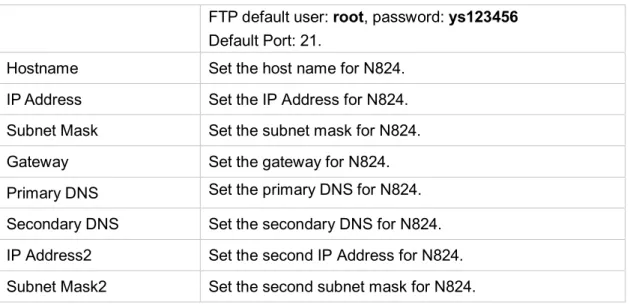
Default Port: 8022. Enable FTP
Users could log in N824 via FTP if this option is enabled. Users could access FTP resource on N824 via Windows explorer or Web browser.
N824 User Manual FTP default user: root, password: ys123456
Default Port: 21.
Hostname Set the host name for N824. IP Address Set the IP Address for N824. Subnet Mask Set the subnet mask for N824. Gateway Set the gateway for N824. Primary DNS Set the primary DNS for N824. Secondary DNS Set the secondary DNS for N824. IP Address2 Set the second IP Address for N824. Subnet Mask2 Set the second subnet mask for N824.
Security Center
Users are strongly recommended to configure firewall and other security options on N824 to prevent the attack fraud and the system failure or calls loss.
Security Center
All the security settings including Firewall, Service, Port Settings in N824 are displayed in Security Center. Users could rapidly check and configure the relevant security settings here.
Firewall
In the “Firewall” tab, users could check firewall configuration and alert settings. By clicking the relevant button, you can enter the configuration page directly.
Figure 5-2 Security Center—Firewall
Service
In “Service” tab, you can check AMI/SSH status. For AMI/SSH, you can enter the according page by clicking the button in “Setting” column.
N824 User Manual
Figure 5-3 Security Center—Service Port
In “Port” tab, you can check SIP port and HTTP port. You can also enter the relevant page by clicking the button in “Setting” column.
Figure 5-4 Security Center—Port
Firewall Rules
Firewalls are used to prevent unauthorized Internet users from accessing private networks connected to the Internet, especially intranets. All messages entering or leaving the intranet pass through the firewall, which examines each message and blocks those that do not meet the specified security criteria.
N824 User Manual 1) General Settings
Table 5-2 Description of Firewall General Settings
Items Description
Enable Firewall Enable the firewall to protect the device. You should reboot the device to make the firewall run. Disable Ping Enable this item to drop net ping from remote hosts.
Drop All
When you enable “Drop All” feature, the system will drop all packets or connection from other hosts if there are no other rules defined. To avoid locking the devices, at least one “TCP” accept common rule must be created for port used for SSH access, port used for HTTP access and port sued for CGI access.
2) Common Rules
There is no default rule; you can create one as required.
Figure 5-6 Common Rules Table 5-3 Description of Common Rules
Items Description
Name A name for this rule, e.g. “HTTP”.
Description Simple description for this rule. E.g. accept the specific host to access the Web interface for configuration.
Protocol The protocols for this rule.
Port Initial port should be on the left and end port should be on the right. The end port must be equal to or greater than start port.
IP
The IP address for this rule. The format of IP address is: IP/mask E.g. 192.168.5.100/255.255.255.255 for IP 192.168.5.100
E.g. 192.168.5.0/255.255.255.0 for IP from 192.168.5.0 to 192.168.5.255.
MAC Address The format of MAC Address is XX:XX:XX:XX:XX:XX, X means 0~9 or A~F in hex, the A~F are not case sensitive.
N824 User Manual
Action
Accept: Accept the access from remote hosts. Drop: Drop the access from remote hosts. Ignore: Ignore the access.
Note: the MAC address will be changed when it’s a remote device, so it will not be working to filter using MAC for remote devices.
IP Blacklist
You can set some packets accept speed rules here. When an IP address, which hasn’t been accepted in common rules, sends packets faster than the allowed speed, it will be set as a black IP address and be blocked automatically.
Figure 5-7 IP Blacklist Settings Page 1) Blacklist rules
We can add the rules for IP blacklist rate as demanded.
Figure 5-8 Add Blacklist Rule
Table 5-4 Description of Auto Blacklist Rules
Items Description
Port Auto defense port
Protocol Auto defense protocol. TCP or UDP.
IP Packets Allowed IP packets number in the specific time interval.
Time interval The time interval to receive IP packets. For example, IP packets 90, time interval 60 means 90 IP packets are allowed in 60 seconds. 2) IP blacklist
N824 User Manual The blocked IP address will display here, you can edit or delete it as you wish.
AMI Settings
The Asterisk Manager Interface (AMI) is a system monitoring and management interface provided by Asterisk. It allows live monitoring of events that occur in the system, as well enabling you to request that Asterisk perform some action. The actions that are available are wide-ranging and include things such as returning status information and originating new calls. Many interesting applications have been developed on top of Asterisk that take advantage of the AMI as their primary interface to Asterisk.
There are two main types of messages on the Asterisk Manager Interface: manager events and manager actions.
The 3rd party software can work with N824 using AMI interface. It is disabled by
default. If necessary, you can enable it.
Figure 5-9 AMI Settings • Username & password
After enabling AMI, you can use this username and password to log in N824 AMI.
• IP Restriction
You can set which IP is allowed to log in N824 AMI interface.
Certificates
N824 supports TLS SIP extension and VoIP trunk. Before you register TLS extension/trunk to N824, please upload certificates first.
N824 User Manual
Figure 5-10 Certificates • Trusted Certificate
This certificate is a CA certificate. When selecting “TLS Verify Client” as “Yes”, you should upload a CA. The relevant IPPBX/SIP phone should also have this certificate.
• Gateway Certificate
This certificate is server certificate. No matter selecting “TLS Verify Client” as “Yes” or “NO”, you should upload this certificate to N824. If IPPBX/SIP phone enables “TLS Verify server”, you should also upload this certificate on IPPBX/SIP phone.
Alert Settings
After enabling this feature, phone notification or email notification will be sent to users if the system has been attacked via IP or Web.
Figure 5-11 Alert Settings • IPATTACK
When the system is attacked by IP address, the firewall will add the IP to auto IP Blacklist and notify the user if it match the protection rule.
• WEBLOGIN
Web Login Alert Notification: enter the incorrect password consecutively for five times will be considered as an attack, the system will limit the IP login within 10 minutes and notify the user.
1) Phone Notification Settings
Table 5-5 Description of Phone Notification Settings
Items Description
N824 User Manual multiple extension and outbound phone numbers. Please
separate them by “;”.
Example: “500;9911”, if the extension has configured Follow Me Settings, the call would go to the forwarded number directly. Attempts The attempts to dial a phone number when there is no answer. Interval The interval between each attempt to dial the phone number.
Must be greater than 3 seconds, the default value is 10 seconds. Prompt Users will hear the prompt while receiving the phone notification. 2) Email Notification Settings
Please ensure that all voicemail settings are properly configured on the PBX→Basic Settings→Voicemail Settings page before using this feature.
Table 5-6 Description of Email Notification Settings
Items Description
Recipient’s Name
The recipients for the alert notification, and multiple email addresses are allowed, please separate them by “;”. Example:jerry@yeastar.com;jason@yeastar.com,
456@sina.com .
Subject The subject of the alert email.
Email Content
Text content supports predefined variables. Variable names and corresponding instructions are as follows:
$(HOSTNAME) Host name $(LOCALIP) Local IP address
$(SOURCEIP) Attack source IP address $(DATETIME) Occurred
$(USERNAME) User name (WEBLOGIN effective) $(DESTMAC) Attacks destination MAC (IPATTACK effective)
$(DESTPORT) Attacks destination Port number (IPATTACK effective)
$(PROTOCOL) Protocol type (IPATTACK effective) $(INTERFACE) Network interface name (IPATTACK effective)
Password Settings
It is highly recommended to change the system’s password after first login. Go to System→System Preferences→Password Settings to change the password.
N824 User Manual
Figure 5-12 Change Password 1. Enter the old password first.
2. Enter a new password and retype the new password to confirm. The password complexity will be detected, which will help users to set a strong password and make N824 safer. A strong password is comprised of letters, numbers and characters.
3. Save the changes, the user will be automatically logged out. 4. Log in N824 using the new password.
Date and Time
Please adjust the time of N824 (including the time zone) consistent with your local time. Go to System→System Preferences→Date and Time to configure the system date and time.
Figure 5-13 Configuring Date & Time • Time Zone
Select your current and correct time zone on N824. • Daylight Saving Time
The option is disabled by default. Enable it when necessary. • Automatically Synchronize with an Internet Time Server
N824 will adjust its internal clock to a central network server. Please note theN824 should be able to access to the Internet if you choose this method. • Set Date & Time Manually
Enter the time using the numbers on your keyboard. Note:
N824 User Manual
Extensions
This chapter explains how to create and configure extensions on N824. It supports SIP extensions and FXS extensions, go to PBX→ Extensions and Trunks→ Extensions page to configure the extensions.
• FXS Extensions • VoIP Extensions
FXS Extensions
There are 24 FXS extensions on N824. Users could click to edit each FXS extension.
FXS Extension Configuration
The extension settings are divided into Account, General Settings, Advanced Settings, Management Settings and Timer Settings.
1) Account
On this page, users could fill in the user information, including Name, Telephone number, Job, Wechat ID and Email address. If an image of the account was uploaded via the Linkus App, you could see the account’s image here.
Figure 6-1 Account Information
Configure Linkus Mobile Client Settings if you want to register this extension to the Linkus App.
N824 User Manual Table 6-1 FXS Extension Linkus Mobile Client Settings
Items Description
Enable Calling Capability in Mobile Client
Allow the user to make and receive calls with Links Mobile Client. Please make sure that the corresponding App has been installed on your phone.
Ring Strategy
Set ring strategy between the FXS extension and mobile extension.
• FXS Extension First
• Mobile Client Extension First
Connecting Route The route is used to connect Linkus and the PBX, so N824 will always use this route to dial Linkus.
Password for Linkus and Web
The password to register mobile extensions and log in the user Web interface.
User Web Interface
Check this option to allow the user to login to the N824 User Web interface, which can be used to check voicemail and extension recordings.
2) General Settings
Table 6-2 FXS Extension Configuration- General Settings
Items Description
Extension The numbered extension, which will be associated with this particular User/Phone. Caller ID The Caller ID will be used when this user calls another internal
extension. Voicemail
• Enable Voicemail
Enable voicemail for the user. • Voicemail Access PIN
The voicemail password (digits only) for the user to access the voicemail box.
Mail Settings
• Enable Send Voicemail
Once enabled, the voicemail will be sent toaconfigured email address.
• Email Address
Email address used to receive the voicemail or Fax.
Note: please ensure that the section “SMTP Settings For Voicemail” (in the “Voicemail Settings”) has been properly configured before using this feature.
Hotline
• Enable Hotline: whether to use hotline. • Hotline Number: set a hotline number.
• Delay Dial: define how long to make Hotline call after you pick up the call.
N824 User Manual the last hook-flash event received by N824 before it will recognize a second event. If a second event occurs in less time than defined by Hook Flash Detection, then N824 will ignore the event. The default value of Flash is 1000 ms.
Pickup Group
If this extension belongs to a pickup group, any calls that ring this extension can be picked up by other extensions in the same pickup group by dialing the Call Pickup feature code (the default is *4).
Note: *4 is the default setting, it can be changed under Feature Codes→ General → Call Pickup.
Max Call Duration
Setup the max cull duration for every call of this extension, but it’s only valid for outbound calls. Enter “0” or leave this blank empty, the value would be equal to the max call duration configured in the Option Settings page.
Note: this setting will not be valid for internal calls. 3) Advanced Settings
Table 6-3 FXS Extension Configuration- Advanced Settings
Items Description
Call Waiting
Check this option if the extension should have Call Waiting capability. If this option is checked, the “When busy” follow me options will not be available. The call waiting function of IP phone has higher priority than N824’s call waiting function. DND Don’t Disturb. When DND is enabled for an extension, the
extension will not be available. Enable Busy
Camp-on
If a dialled extension or a desired line is busy, with this feature, when the extension or line becomes idle, your telephone will ring automatically, so you can pick up to speak with the extension or seize the line and dial an external number.
Ring Out Check this option if you want to customize the ring time. Ring tone will stop over the time defined.
Follow me
Call forwarding for an extension can be configured here. The administrator can configure Follow Me option for this extension. If you want to transfer the call to an outbound number, please follow the dial pattern of outbound route filled in the outbound number.
For example: transferring to your mobile phone number 123456789, the dial pattern of outbound route is “9.”, you should fill in 9123456789 here.
Volume Settings
• Rxgain
The Volume sent to FXS extension. • Txgain
N824 User Manual
Caller ID Type Normally, you choose the “default” option except for using N824 in Japan, in which case you should choose “Japan”.
Spy Settings
There are 4 spy modes available: • General spy
You have the permission to use the following 3 modes. • Normal spy
You can only hear the call, but can't talk • Whisper spy
You can hear the call, and can talk with the monitored extension
• Barge spy
You can hear the call and talk with them both Example:
If 500 want to monitor extension 501, we need to enable the “allow being spied” for 501, and choose the spy mode for extension 500.
Then pick up 500 and dial “feature codes + 501” to start monitoring when 501 is in a call.
If 500 choose “normal spy”, it should dial “*90501” to start monitoring.
If 500 choose “whisper spy”, it should dial “*91501” to start monitoring.
If 500 choose “barge spy”, it should dial “*92501” to start monitoring.
If 500 choose “general spy”, it can dial “*90501”, “*91501” or “*92501” to start monitoring.
4) Management Settings
Once you enable “User Web Interface” for the extension, you need to also configure the Management settings to set the access permissions.
By default, extension users could check voicemail, one-touch Recordings, and configure settings of their own extensions when logging in User Web Interface. If the user wants to manage the CDR and Auto Recordings, you have to set the access permissions here.
CDR
• View Permission: the permission to view CDR. • Delete Permission: the permission to delete CDR.
• Download Permission: the permission to download CDR.
• Allowed Extension for CDR: choose which extensions’ CDR is allowed to be checked/deleted/downloaded by the user.
N824 User Manual
Figure 6-3 CDR Permissions for FXS Extensions Auto Recordings
• View Permission: the permission to check auto recordings. • Delete Permission: the permission to delete recording files.
• Download Permission: the permission to download auto recording files. • Allowed Extension for Recordings: choose which extensions’ auto recording
files are allowed to be checked/deleted/downloaded by the user.
Figure 6-4 Auto Recordings Permissions for FXS Extensions 5) Timer Settings
Want the phone to wake you? Click Timer Settings Section, set your wake-up time and other options, and give the alarm a name (like “Good morning”).
N824 User Manual
Figure 6-5 Timer Settings for FXS Extensions Batch Edit FXS Extensions
Users could batch edit the selected FXS extensions’ number, timer settings and other settings.
• Modify the Number of the Selected Extensions
Click to modify the selected
extensions. Define the extension number starting from a number.
Figure 6-6 Modify Number of the Selected Ports • Edit the Selected Extensions
Click , you can edit the selected extensions’
General Settings, Voicemail, Volume, Hotline, Follow me and Group Settings. • Edit the Selected Timers
Click to set alarms for the selected extensions.
• Delete the Selected Extensions
N824 User Manual
VoIP Extensions
Users could extend VoIP extension by clicking to add on VoIP extension. N824 supports up to 8 VoIP extensions.
VoIP Extension Configuration
The extension settings are divided into Account, General Settings, Advanced Settings, Management Settings and Timer Settings.
1) Account
On this page, users could fill in the user information, including Name, Telephone number, Job, Wechat ID and Email address. If an image of the account was uploaded via the Linkus App, you could see the account’s image here.
Figure 6-7 Account Information
Configure Linkus MobileClient Settings if you want to register this extension to the Linkus App.
Figure 6-8 SIP Extension Client Settings Table 6-4 SIP Extension Linkus Mobile Client Settings
Items Description
Enable Calling Capability in Mobile Client
Allow the user to make and receive calls with Linkus Mobile Client. Please make sure that the corresponding APP has been installed on your phone.
N824 User Manual extension.
• SIP Extension First
• Mobile Client Extension First
Connecting Route The route is used to connect Linkus and the PBX, so N824 will always use this route to dial Linkus.
Password for Linkus and Web
The password to register mobile extensions and log in the user web interface.
User Web Interface
Check this option to allow the user to login to the N824 User Web interface, which can be used to check voicemail and extension recordings.
2) General
Table 6-5 VoIP Extension Configuration- General
Items Description
Extension The numbered extension, which will be associated with this particular User/Phone.
Password The password for this extension.
Caller ID The Caller ID will be used when this user calls another internal extension. Enable Voicemail Enablevoicemail for the user.
Voicemail Access PIN
The voicemail password (digits only) for the user to access the voicemail box.
Enable Send Voicemail
Once enabled, the voicemail will be sent to a configured email address.
Email Address
Email address used to receive the voicemail or Fax.
Note: please ensure that the section “SMTP Settings For Voicemail” (in the “Voicemail Settings”) have been properly configured before using this feature.
Pickup Group
If this extension belongs to a pickup group, any calls that ring this extension can be picked up by other extensions in the same pickup group by dialing the Call Pickup feature code (the default is *4).
Note: *4 is the default setting, it can be changed under Feature Codes→General → Call Pickup.
Max Call Duration
Setup the max cull duration for every call of this extension, but it’s only valid for outbound calls. Enter “0” or leave this blank empty, the value would be equal to the max call duration configured in the Option Settings page.
Note: this setting will not be valid for internal calls. NAT
This setting should be used when the system is using a public IP address to communicate with devices hidden behind a NAT device (such as a broadband router). If you have one-way audio problems, you usually have problems with your NAT
N824 User Manual configuration or your firewall's support of SIP and/or RTP ports. Qualify Send check alive packets to IP phones.
Enable SRTP Enable extension for SRTP (RTP Encryption).
Transport This will be the transport method used by the extension. The options are UDP (default) or TCP or TLS.
DTMF Mode RFC4733, Info, Inband, Auto. Remote Register
Allow to register remote extensions.
If you enable “Remote Register”, the extension password must include uppercase letters, lowercase letters, and digits.
3) Advanced Settings
Table 6-6 VoIP Extension Configuration—Advanced Settings
Items Description
Call Waiting
Check this option if the extension should have Call Waiting capability. If this option is checked, the “When busy” follow me options will not be available. The call waiting function of IP phone has higher priority than N824’s call waiting function. DND Don’t Disturb. When DND is enabled for an extension, the
extension will not be available. Enable Busy Camp-
on
If a dialled extension or a desired line is busy, with this feature, when the extension or line becomes idle, your telephone will ring automatically, so you can pick up to speak with the extension or seize the line and dial an external number.
Ring Out Check this option if you want to customize the ring time. Ring tone will stop over the time defined.
Follow me
Call forwarding for an extension can be configured here. The administrator can configure Follow Me option for this extension. If you want to transfer the call to an outbound number, please follow the dial pattern of outbound route filled in the outbound number.
For example: transferring to your mobile phone number 123456789, the dial pattern of outbound route is “9.”, you should fill in 9123456789 here.
IP Restriction
• Enable IP Restriction
Check this option to enhance the VoIP security for MyPBX. If this option is enabled, only the permitted IP/Subnet mask will be able to register this extension number. In this way, the VoIP security will be enhanced.
• Permitted “IP address/Subnet mask”
The input format should be “IP address” + “/” + “Subnet mask”.
N824 User Manual device whose IP address is 192.168.5.100 is allowed to register this extension number.
E.g."192.168.5.0/255.255.255.0" means only the device whose IP address is 192.168.5.XXX is allowed to register this extension number.
Spy Settings
There are 4 spy modes available: • General spy
You have the permission to use the following 3 modes. • Normal spy
You can only hear the call, but can't talk. • Whisper spy
You can hear the call, and can talk with the monitored extension.
• Barge spy
You can hear the call and talk with them both. Example:
If 500 want to monitor extension 501, we need to enable the “allow being spied” for 501, and choose the spy mode for extension 500.
Then pick up 500 and dial “feature codes + 501” to start monitoring when 501 is in a call.
If 500 choose “normal spy”, it should dial “*90501” to start monitoring.
If 500 choose “whisper spy”, it should dial “*91501” to start monitoring.
If 500 choose “barge spy”, it should dial “*92501” to start monitoring.
If 500 choose “general spy”, it can dial “*90501”, “*91501” or “*92501” to start monitoring.
4) Management Settings
Once you enable “User Web Interface” for the extension, you need to also configure the Management settings to set the access permissions.
By default, extension users could check voicemail, one-touch Recordings, and configure settings of their own extensions when logging in User Web Interface. If the user wants to manage the CDR and Auto Recordings, you have to set the access permissions here.
CDR
• View Permission: the permission to check CDR. • Delete Permission: the permission to delete CDR.
• Download Permission: the permission to download CDR.
• Allowed Extension for CDR: choose which extensions’ CDR is allowed to be checked/deleted/downloaded by the user.
N824 User Manual
Figure 6-9 CDR Permissions Auto Recordings
• View Permission: the permission to check auto recordings. • Delete Permission: the permission to delete recording files.
• Download Permission: the permission to download auto recording files. • Allowed Extension for Recordings: choose which extensions’ auto recording
files are allowed to be checked/deleted/downloaded by the user.
Figure 6-10 Auto Recording Permissions 5) Timer Settings
Want the phone to wake you? Click Timer Settings Section, set your wake-up time and other options, and give the alarm a name (like “Good morning”).
N824 User Manual
N824 User Manual
Trunks
External calls can be made through CO lines or via VoIP trunks on N824. In this chapter, we give a simplified guide to the N824 users in setting up trunks. We describe CO lines configurations and how to configure N824 to work with VoIP Providers. • CO Lines
• VoIP Trunks
CO Lines
CO lines also known as PSTN trunks. The public switched telephone network (PSTN) is the network of the world's public circuit-switched telephone networks.
Go to PBX→Extensions and Trunks→Trunks→CO lines to edit the CO lines. Before configuring a CO line, please make sure that the CO line is connected to N824 CO port.
Click to edit the CO line.
CO Line Configuration
Please check the CO line configuration parameters below. 1) General Settings
Table 7-1 CO Line-General Settings General Settings
Trunk Name A unique label used to identify this trunk. Volume Setting Set the volume for this trunk. The default is 40%. 2) Hangup Detection
Hangup detection settings help the system to detect if a call is hung up. If you find the PSTN call could not be disconnected, these settings need to be configured.
Table 7-2 CO Line-Hangup Detection Hang up Detection
Hangup Type
Choose the Hangup type. • Default
• Busy Tone • Polarity
N824 User Manual
Busy Count
If Busy Detection is enabled, it is also possible to specify how many busy tones to wait for before disconnecting the call. The default is 4, but better results can be achieved if set to 6 or even 8. Remember, the higher the number, the more time will be required to release a channel. A higher setting lowers the probability that you will encounter random hang-ups.
Busy Interval The busy detection interval.
Busy Pattern
If Busy Detection is enabled, it is also possible to specify the cadence of your busy signal. In many Countries, it is 500msec on, 500msec off. Without Busy Pattern specified, N824 will accept any regular sound-silence pattern that repeats <Busy Count> times as a busy signal. If you specify Busy Pattern, then N824 will further check the length of the tone and silence, which will further reduce the chance of a false positive disconnection.
Frequency Detection Used for Frequency Detection (Enable detecting the busy signal frequency or not).
Busy Frequency If the Frequency Detection is enabled, you must specify the local frequency. Hangup Polarity
Detection
The call will be considered as “hang up” on a polarity reversal.
Silence Timeout Define the ring out value (in seconds) for this trunk. 3) Answer Detection
Answer Detection" will help the system to accurately bill your calls.
If the CO line could send polarity reversal signal after a call is established, you could choose "Polarity Detection" in this field. If not, you could choose "Ring Detection" and configure the rest of the settings accordingly.
Table 7-3 CO Line-Answer Detection Answer Detection
Answer Detection
Select which type to detect the call as answered.
• Default: N824 will start to charge once you grab the CO line to call out, whether the call is answered or not. • Polarity Detection: if the CO line supports polarity, you
can choose "Polarity detection". When the callee answers the call, the provider will send a polarity signal, and then N824 starts to bill.
• Ring Detection: if you choose this option, N824 will charge the call according to CO line ring back tone detection. When the "ring duration" or the "ring interval duration" detected on N824 is larger than the standard
N824 User Manual parameters or custom parameters, the call is detected as ANSWERED.
*Standard parameters: when you configure the "Tone Zone Settings" under PBX→BasicSettings→General Preferences you can get the country's standard tone parameters.
Custom Ring Tone Enable or disable Custom Ring Tone. If the custom ring tone is enabled, you need to configure the following settings according to the ringback signal.
Max Ring Duration Max duration of the ring tone. Max Ring Interval
Duration Max pause between the two ring tones.
Min Ring Detection Enable Min Ring Detection, which is useful for complex situations, like when jitter or noise occurs on the PSTN line. Generally it is disabled.
Min Ring Duration Min duration of the received tone. Min Ring Interval
Duration
Min pause between the two received tones.
4) Caller ID Settings
Caller ID Settings will help the system to detect Caller ID. If an incoming PSTN call does not display Caller ID, you need to confirm with your service provider if the line has enabled Caller ID feature. If this line does support Caller ID, configure these settings to solve this problem.
Table 7-4 CO Line-Caller ID Settings Caller ID Settings
Caller ID Detection Enable/Disable the Caller ID detection.
Caller ID Start
This option allows you to define the start of a Caller ID signal.
• Ring: start when a ring is received (Caller ID Signaling: Bell_USA, DTMF).
• Polarity: start when a polarity reversal is started (Caller ID Signaling: V23_UK, V23_JP, DTMF).
• Before Ring: start before a ring is received (Caller ID Signaling: DTMF).
Caller ID Signaling
This option defines the type of Caller ID signaling to use. It can be set to one of the following:
• Bell: bell202 as used in the United States • v23_UK: suitable in the UK
• v23_Japan: suitable in Japan • v23-Japan pure: suitable in Japan
N824 User Manual 5) DNIS Settings
DNIS (Dialed Number Identification Service) is a telephone service that identifies for the receiver of a call the number that the caller dialed.
Table 7-5 CO Line-DNIS Settings DNIS Settings
Enable DNIS Tick to enable DNIS for this trunk. DNIS Name Define the DINS name.
6) Other Settings
Table 7-6 CO Line-Other Settings Other Settings
Ring Detect Timeout
FXO (FXS signalled) devices must have a timeout to determine if there was a hangup before the line was answered. Rang from 1000 to 8000.
N824 User Manual
VoIP Trunks
N824 supports up to 4 VoIP trunks, which helps you to expand VoIP service on the device.
Go to PBX→ Extensions and Trunks→ VoIP Trunks to edit the VoIP trunks.
• Click to add one VoIP trunk.
• Click to delete the selected VoIP trunks.
• Click to edit the VoIP trunk. • Click to delete the VoIP trunk. VoIP Trunk Configuration
Please check the VoIP trunk configuration parameters below. 1) General Settings
Table 7-7 VoIP Trunk-General Settings General Settings
Enable/Disable Enable or Disable this VoIP trunk.
Provider Name A unique label to help you identify this trunk.
Hostname/IP Service provider’s hostname or IP address. Default port: 5060.Don’t change this part if it is not required. Domain
VoIP provider’s server domain name.
If no domain name for the provider. Fill in the IP address instead.
User Name The user name to register to the trunk from the VoIP provider. Authorization Name Used for SIP authentication.
Password The password to register to the trunk from the VoIP provider. From User
All outgoing calls from this SIP Trunk will use the From User (In this case the account name for SIP Registration) in From Header of the SIP Invite package. Keep this field blank if not needed.
Online Number
Define the online number that expected by “Skype Connect” and some other SIP service providers. Leave this field blank if not needed.
Maximum Channels
Control the maximum number of outbound channels (simultaneous calls) that can be used on this trunk. Inbound calls are not counted against the maximum. Set as 0 to specify no maximum.
N824 User Manual
Caller ID
Specify the caller ID to use when making outbound calls over this trunk. The caller ID set in the “Extension” page will override the caller ID set in the “VOIP trunk” page. Please note that not all the service providers support this feature. Contact your service provider for more information.
Realm Realm is a string to be displayed to users so they know which username and password to use.
Authenticating Incoming
• Yes: when an incoming call reaches N824 and sends INVITE packet to N824, N824 responds 401, but the Realm info in 401 Response does not match the Realm set on VoIP trunk, the provider will refuse to authenticate. • No: N824 will not reply a 401 Response to the provider to
authenticate the incoming call. Enable Outbound
Proxy Server
A proxy that receives requests from a client. Even though it may not be the server resolved by the Request-URI.
Codecs Define the codec for this sip trunk and its priority Transport
This will be the transport method used by the SIP Trunk. This method is given by the SIP trunk provider. The options are UDP (default) or TCP or TLS.
Enable SRTP Define if SRTP is enabled for this trunk. Qualify Send check alive packets to the sip provider.
DTMF Mode Set default mode for sending DTMF of this trunk. Default setting: rfc4733.
2) DNIS Settings
Table 7-8 VoIP Trunk-DNIS Settings DNIS Settings
Enable DNIS Tick to enable DNIS for this trunk. DNIS Name Define the DINS name.
DID Number Set the DID Number for this trunk. 3) DOD Settings
DOD (Direct Outward Dialing) means the caller ID displayed when dialing out. Before configuring this, please make sure the provider supports this feature. • Associated Extension
The extension making call out via SIP Trunk will display the associated DOD. • Add DOD
Add DOD for one associated extension. • Add Bulk DOD
N824 User Manual
Figure 7-1 VoIP Trunk DOD Settings
Add bulk DOD for bulk extensions in ascending sequence with the “Begin DOD” you fill in. For example, if the Associated Extensions are 100, 101, 102, 103, 104, 105 with “Begin DOD” as 5500100, the corresponding DOD will be 5500100, 5500101, 5500102, 5500103, 5500104, and 5500105.
N824 User Manual
Call Control
This chapter shows you how to control outbound calls and incoming calls with outbound routes and inbound routes.
• Outgoing Rules • Incoming Rules • PIN Settings • Blacklist
Outgoing Rules
Outbound Route
An outbound route works like a traffic cop giving directions to road users to use a predefined route to reach a predefined destination. Outbound routes are used to specify what numbers are allowed to go out a particular route. When a call is placed, the actual number dialed by the user is compared with the dial patterns in each route (from highest to lowest priority) until a match is found. If no match is found, the call fails. If the number dialed matches a pattern in more than one route, only the rules with the highest priority in the route are used.
Note:
• N824 compares the number with the pattern that you have defined in your route 1. If matches, it will initiate the call using the selected trunks. If it does not, it will compare the number with the pattern you have defined with route 2 and so on. The outbound route which is in a higher position will be matched firstly.
• Adjust the outbound route sequence by clicking these buttons . Go to PBX→Outbound Call Control→Outgoing Rules to edit outbound routes. Please check the outbound route configuration parameters below.
1) General Settings
Table 8-1 Outbound Route-General Settings
Options Description
Route Name Used to identify the route. The name is usually descriptive, i.e. "local" or "international".
Password
OPTIONAL.
Select a PIN list from PIN Settings to set password for the outbound route. A route can prompt users for a password
N824 User Manual before allowing calls to process. Leave this field blank if you don't want to restrict this outbound route.
T.38 Support Enable or disable T.38 FAX on this outbound route. Only for SIP Trunk. Rrmemory Hunt
Round Robin with memory. If it is enabled, N824 will remember which trunk was used last time, and then use the next available trunk to call out.
Office Hours
This is an option to limit when the outbound route is available to use. Usually we can select an office hours that is same as your working hours, and the outbound route would be unavailable after work.
2) Dial Patterns
A dial pattern is a unique set of digits that will select this route and send the call to the designated trunks. Multiple Dial Patterns can be added on one outbound route by clicking button.
Table 8-2 Outbound Route-Dial Patterns Patterns
X Refers to any digit between 0 and 9 Z Refers to any digit between 1 and 9 N Refers to any digit between 2 and 9 [###]
Refers to any digit in the brackets, example [123] is 1 or 2 or 3. Note that multiple numbers can be separated by commas and ranges of numbers can be specified with a dash ([1.3.6-8]) would match the numbers 1, 3, 6, 7 and 8.
. (dot) Wildcard. Match any number of anything.
! Used to initiate call processing as soon as it can be determined that no other matches are possible. Strip
Allow the users to specify the number of digits that will be stripped from the front of the phone number before the call is placed.
For example, if users must press 0 before dialing a phone number, one digit should be stripped from the dial string before the call is placed.
Prepend
Digits to prepend to a successful match. If the dialed number matches the patterns, then this will be prepended before sending to the trunks.
For example if a trunk requires 10-digit dialing, but users are more comfortable with 7-digit dialing, this field could be used to prepend a 3-digit area code to all 7-digit phone numbers before the calls are placed. When using analog trunks, a “w” character may also be prepended to provide a slight delay before dialing.
N824 User Manual 3) Member Extensions
Move the extensions could call through this outbound route to "Selected" Box.
Figure 8-1 Outbound Route-Member Extensions 4) Member Trunks
Move the trunks that would be used on this outbound route to "Selected" Box.
Figure 8-2 Outbound Route-Member Trunks
Seize a Line
On a traditional PBX, users have to seize a CO Line before dialing outside number. To adapt to these users’ habits, we retain this feature. Users could seize an available CO Line by dialing a pre-configured number (default: 9), then get a dial tone and dial the external number to call out.
N824 User Manual
Incoming Rules
When a call comes into N824 from the outside, N824 needs to know where to direct it. It can be directed to an extension, a ring group, a queue or a digital Receptionist (IVR) etc.
Go to PBX→Inbound Call Control→ Incoming Rules to edit incoming rules. Please check the inbound route configuration parameters below.
1) General Settings
Table 8-3 Inbound Route-General Settings
Options Description
Route Name Used to identify the route.
DID Number
Routing calls based on the trunk on which the call is coming in. In the DID field, you will define the expected “DID Number” if your trunk passes DID on incoming calls. Leave this blank to match calls with any or no DID info. The DID number entered must match the format of the provider sending the DID. You can also use a pattern match to match a range of numbers.
Caller ID Number
Routing calls based on the caller ID number of the person that is calling. Define the caller ID number to be matched on incoming calls. Leave this field blank to match any or no CID info.
2) Trunk Members
Select which trunks will be member trunks for this route. To make a trunk a member of this route, please move it to the “Selected” box.
Figure 8-4 Inbound Route-Member Trunks 3) Business Days
N824 User Manual
Figure 8-5 Inbound Route-Business Days • Office Hours
Select one defined business days office hours. • Office Hours Destination
Configure where to route the incoming calls during office hours. • Non-office Hours Destination
Configure where to route the incoming calls during non-office hours. Table 8-4 Inbound Route-Business Days
Destination Description
End Call Route the incoming calls to end calls, the system will auto hang up the call.
Extension Route the incoming calls to a specific extension. Voicemail Route the incoming calls to an extension’s voicemail. IVR Route the incoming calls to a specific IVR.
Ring Group Route the incoming calls to a specific Ring Group.
Conference Room Used to initiate call processing as soon as it can be determined that no other matches are possible.
DISA Route the incoming calls to a specific DISA. Queues Route the incoming calls to a specific Queue. Faxes
Route the incoming faxes to a specific extension’s mail address.
Note: this function only supports T.38 faxes. 4) During Holidays
Define where the calls will be routed during Holidays.
Figure 8-6 Inbound Route-During Holidays • Holiday
Select which defined Holiday to use. When a time is defined in both Business Days and Holidays, it will be treated as Holidays.
N824 User Manual Configure where to route the incoming calls during holidays.
5) Fax Detection
Enable or disable the "Fax Detection" functionality on this route.
Figure 8-7 Inbound Route-Fax Detection • No Detect
No attempts are made to auto-determine the call type. All calls are sent to the defined destination.
• Custom Email
Customize an E-mail address to receive the faxes. You should first configure the “Voicemail Settings->SMTP Settings for Voicemail” correctly before you use this option.
• Faxes
Send faxes to an extension. If choosing a FXS extension here, the fax will be sent to the FXS port selected, you should connect a fax machine to this FXS port. If choosing a VoIP extension, the fax will be sent to the extension’s voicemail as an attachment.
Note:
If you want to receive faxes with custom Email address, the SMTP Settings should be configured successfully in advance. If you want to receive faxes with E-mail address configured in VoIP extension voicemail, you should first make sure the tested email to your email address works fine.
PIN Settings
Go to PBX→Advanced Settings→ PIN Settings to create a PIN list. The PIN lists can be selected to access restricted features. The PIN can also be added to the CDR record’s “Account Code” field. PIN list can be applied to Outbound Route.
N824 User Manual
Blacklist
Blacklist is used to block an incoming/outgoing call. If the number of incoming/outgoing call is registered in the number blacklist, the caller will hear the following prompt: “The number you have dialed is not in service. Please check the number and try again”. The system will then disconnect the call.
Go to PBX→Advanced Settings→Blacklist to add numbers to the blacklist. You can choose to block the number for inbound, outbound or both.
• If the type is “inbound”, then this number can’t be called.
• If the type is “outbound”, then the extensions in N824 can’t call this number.
N824 User Manual
IVR
Like most organizations, where possible, we would like to route incoming calls an Auto Attendant. You can create one or more IVR (Auto Attendant) on N824 to achieve it. When calls are routed to an IVR, N824 will play a recording prompting them what options the callers can enter such as “Welcome to XX, press 1 for Sales and press 2 for Technical Support”.
Configure IVR
Go to PBX→Inbound Call Control→IVR to configure IVR. • Click to add a new IVR.
• Click to delete the selected IVR.
• Click to edit one IVR. • Click to delete one IVR.
Please check the IVR configuration parameters below.
Table 9-1 IVR Configuration Parameters-General Settings General Settings
Number N824 treats IVR as an extension; you can dial this extension number to reach the IVR from internal extensions. Name Set a name for the IVR.
Prompt
Choose which recording to be played to the caller when they reach the IVR. You can choose the default prompt on N824 or choose a Custom Prompt which is uploaded or created on N824.
Repeat Count The number of times that the selected IVR prompt will be played.
Key Timeout
How long (in seconds) we wait for the caller to enter an option on their phone keypad before we consider it timed out and it follows the Timeout Destination as defined below.
Enable Direct Dial
Tick this option to enable Direct Dial. If Direct Dial is enabled, the callers can enter a user's extension number when entering the IVR to go direct to the users.
N824 User Manual Key Press Events
Key Press Event 0 1 2 3 4 5 6 7 8 9 # * Timeout Invalid
Select the destination for each key pressing: digits 0-9, “#”, “*”, Timeout and Invalid. When the callers press the corresponding key, the call will be routed to:
• Extension • Voicemail • Ring Group • IVR • Conference Room • DISA • Queues • Faxes • Dial by Name • Hangup
N824 User Manual
Ring Group
A ring group helps you to ring a group of extensions in a variety of ring strategies. For example, you could define all the technical support guys' extensions in a ring group and ring the support guys one by one.
Configure Ring Group
Go to PBX→Inbound Call Control→ Ring Group to configure ring group.
• Click to add a new Ring Group.
• Click to delete the selected ring groups.
• Click to edit one Ring Group. • Click to delete one Ring Group.
Please check the Ring Group configuration parameters below. 1) General Settings
Table 10-1 Ring Group Configuration Parameters-General Settings General Settings
Ring Group Name Used to identify the ring group.
Ring Group Number This option defines the numbered extension that can be dialed to reach this group.
Strategy
Select an appropriate ring strategy for this ring group.
• Ring All Simultaneously: ring all the available extensions simultaneously.
• Ring Sequentially: ring each extension in the group one at a time.
Seconds to ring each member
Specify how long (in second) to ring each extension or all the extensions.
• If the strategy is “Ring All Simultaneously”, it means the number of seconds to ring this group before routing the call according to the “Destination if No Answer” settings. • If the strategy is “Ring Sequentially”, it means the number
of seconds to ring a single extension before moving on to the next one.
N824 User Manual 2) Ring Group Member
Specify the extensions to be part of this ring group. Move the desired ring group members to the "Selected" Box.
Figure 10-1 Ring Group Member 3) Destination if No Answer
When all members on this group fail to answer the call, system will handle the call according to the selected destination.