Journal of Civil Engineering and Materials Application
Journal home page:
http://journals.rpp.co.ir/jcema Received: Received: 22 October 2018 • Accepted: 25 December 2018
Research
doi: 10.xxxxx/J.JCEMA.12020404
Evaluation of Progressive Collapse in Steel Structures
Designed Based on Iranian Code of Practice for
Seismic Resistant Design Buildings (Standard No.
2800), 4th Edition and Iranian National Building Code
(INBC), Part 10
Goudarz Abkar*, Amir Ashtar Lorki
Department of Civil Engineering, Faculty of Engineering, RobatKarim Branch, Islamic Azad University, Tehran, Iran
*Correspondence should be addressed to Goudarz Abkar, Department of Civil Engineering, Faculty of Engineering, RobatKarim Branch, Islamic Azad University, Tehran, Iran; Tel: +989126043209; Fax: +982166147368; Email: [email protected].
ABSTRACT
In this study, the progressive collapse is examined in steel structures with 4-, 8- and 10-story dual systems of moment resistant and braced frames. Probable risks and unusual loads can lead to progressive collapse in structures, e.g. design or construction errors, fires, gas explosions, accidental overloading, car accidents, bomb explosions, etc. Given the action of these forces over a relatively short period, the dynamic analysis of these incidents appears necessary. In this study, the effect of mentioned incidents is considered through the sudden loss of a member. The studied buildings are designed based to the Iranian National Building Code, Part 6 and Part 10 and Iranian Code of Practice for Seismic Resistant Design Buildings (Standard No. 2800), 4th edition. The structural frames are simulated by finite element method using Abaqus finite element software in order to assess the forces and displacements created in the members. Subsequently, the dynamic response of structure is determined according to the loads and how they are applied to the structure, items of analysis process model (APM) and sudden loss of members. The results of analyses suggest that the loss of middle columns in the studied braced frames is more critical than the loss of corner columns. In other words, the central columns of perimeter frame are more vulnerable than the corner columns.
Key words: Progressive collapse, steel structures, Iranian Code of Practice for Seismic Resistant Design Buildings (Standard No. 2800), progressive failure, Abaqus.
Copyright © 2018 Goudarz Abkar et al. This is an open access paper distributed under the Creative Commons Attribution License.
Journal of Civil Engineering and Materials Applicationis published byRaika Pajuhesh Pars; Journal p-ISSN xxxx-xxxx; Journal e-ISSN 2588-2880.
1. INTRODUCTION
rogressive collapse is defined as the propagation of initial local rupture of a member towards another member, which ultimately results in the failure of whole structure or a large part of it. Possible risks and unusual loads which may cause progressive collapse are: design or construction errors, fires, gas explosions, accidental overloading, car accidents, bomb explosions, etc. Since these risks are less likely to happen, they are not considered in the structural design or they are addressed by indirect measurements. Most of them may cause an action over a relatively short period and lead to dynamic responses. Progressive collapse was first noticed by
in Ronan Point, England. Progressive collapse received the great attention again after the terrorist attacks on the World Trade Center on September 11, 2001. In existing building codes, it is acceptable to design structures for the loads that may be applied during the lifetime of structure. Structures are not usually designed for unusual disasters which can cause global collapse. Most common codes just provide general recommendations for the adjustment of effect of progressive failure in structures loaded more than their design loads. Most standards refer to three design methods for the elimination of progressive collapse. The first method is reducing the exposure to damage and losses; the second and third methods are used to provide progressive
of its highly flexible behavior. Kim showed that the potential of gradual collapse decreases as the number of stories rises (5). Khandelwal et al suggested that the unconventional braced frame is much less prone to the gradual collapse, compared to special concentrically braced frame (SCBF) (6). Kim et al demonstrated that the dynamic amplification factor (DAF) is greater than the two factors both proposed by GSA and UFC (7). Fu remarked that the column loss on higher floors certainly leads to a more vertical displacement under normal and uniform conditions, compared to the column loss on ground floor (8). Kim et al concluded that the pre-fabricated inverted V-type frame show a considerably flexible behavior for gradual collapse among various types of pre-fabricated frames. Asgarian and Hashemi Rezvani showed that the number of braced spans affects the strength of a concentrically braced frame (9). Chen et al conducted an experimental study to investigate the strength of a 2-story moment frame against gradual collapse after a sudden column loss on the ground floor per meter with/without concrete foundation (10). The results showed that concrete foundation plays an important role during the load redistribution process and decreases the potential of gradual collapse. Chen et al addressed the contribution of horizontal bracing towards the gradual collapse resistance of a steel moment frame and concluded that the displacement and rotation angle of the model with horizontal bracing is much smaller than that of the model without horizontal bracing (11). Gerasimidis assessed the vulnerability of steel frames in a gradual collapse through a corner column loss (12). He proposed an analytical method to demonstrate the collapse mechanism of a steel frame for the corner column loss by developing a critical ductility curve. Tavakoli and Rashidi studied the potential flexural strength of a multi-story steel frame with damaged columns in different places under seismic loading (13). The results of their analysis showed that the structure is
et al and Yousefi et al investigated the vulnerability of a 11-story steel moment frame and concluded that the corner column loss on the ground floor leads to the failure of adjacent structure (14, 15). The notes on the subject reveal that the effect of span length on the behavior of steel moment frame against gradual collapse is not noticed by previous scholars adequately. This study aims to assess the effect of span length on the gradual collapse resistance and behavior of seismically designed steel moment frame. Accordingly, three buildings are designed using moment resistant steel frame with different span lengths and a specific length for the frame. The perimeter frame is then examined for the column loss on the first floor in each UFC. Moreover, the dynamic amplification factor (DAF) and demand/capacity ratio (DCR) are calculated to better understand the behavior of structure for a column loss on the first floor.
2. MATERIALS AND METHODS
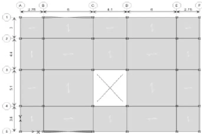
2.1. Geometry of model
In this study, three 4-, 8- and 10-story buildings are designed using ETABS software and conventional structural sections in Iran (Figure 2, Figure 3and Figure 4). These steel buildings have the same floor plans (Figure 1) and all floor heights are assumed 3 m. The lateral load resisting system consists of moderate moment frame in one direction and bracing in another direction. Pinned and fixed connections are used to connect the beams to the columns and to connect the columns to the foundation, respectively. All components are made of the ST37 steel with an ultimate stress of 3700 kg/cm2 and a yielding stress
of 2400 kg/cm2. The dead and live loads are 200 and 335
kg/m2, respectively, for the floors and 150 and 310 kg/m2,
respectively, for the roof. The seismic loads are determined with the assumption that the structure is located in the seismic zone 4 in Iran. The results of structural design are given in Table 1, Table 2 and Table 3.
Figure 2. 3D view of 4-story building assessed via ETABS
Figure 3. 3D view of 8-story building assessed via ETABS
Figure 4. 3D view of 10-story building assessed via ETABS
Table 1. Design results of members of 4-story steel structure
Floors Columns Main beams Braces
Ground floor BOX 25×25×1 2IPE270 2UNP100
First floor BOX 25×25×1 2IPE270 2UNP100
Second floor BOX 20×20×1 2IPE240 2UNP100
Third floor BOX 20×20×1 2IPE240 2UNP80
Table 2. Design results of members of 8-story steel structure
Floors Columns Main beams Braces
Ground floor BOX 45×45×1.6 BOX 25×25×1 2UNP140
First floor BOX 45×45×1.6 BOX 25×25×1 2UNP140
Second floor BOX 40×40×1.6 BOX 25×25×1 2UNP140
Third floor BOX 40×40×1.6 BOX 25×25×1 2UNP120
Fourth floor BOX 40×40×1.6 BOX 25×25×1 2UNP120
Fifth floor BOX 30×30×1.6 BOX 25×25×1 2UNP120
Sixth floor BOX 30×30×1.6 BOX 25×25×1 2UNP100
Seventh floor BOX 30×30×1.6 BOX 25×25×1 2UNP100
Table 3. Design results of members of 10-story steel structure
Floors Columns Main beams Braces
Ground floor BOX 50×50×1.6 BOX 35×35×1.6 2UNP140
First floor BOX 50×50×1.6 BOX 35×35×1.6 2UNP140
Second floor BOX 45×45×1.6 BOX 35×35×1.6 2UNP140
Third floor BOX 45×45×1.6 BOX 35×35×1.6 2UNP120
Fourth floor BOX 45×45×1.6 BOX 35×35×1.6 2UNP120
Fifth floor BOX 35×35×1.6 BOX 30×30×1.6 2UNP120
Sixth floor BOX 35×35×1.6 BOX 30×30×1.6 2UNP100
Seventh floor BOX 35×35×1.6 BOX 30×30×1.6 2UNP100
Eighth floor BOX 30×30×1.6 BOX 30×30×1.6 2UNP80
Ninth floor BOX 30×30×1.6 BOX 30×30×1.6 2UNP80
The samples are designed based on the structures under construction in the current project. Three buildings are considered, which are currently in use. In all three samples, the floor height is 3.2 m and the span is 5 m long. Three buildings with 4- 8- and 10-story dual systems of moment resistant and concentrically braced frames are designed to investigate progressive collapse in braced steel structures
according to the Iranian National Building Code, Part 6 and Part 10, which are about the loads applied to buildings (10) and the design and construction of steel buildings (11), respectively. Seismic requirements of the Iranian Code of Practice for Seismic Resistant Design Buildings (Standard No. 2800) are considered for the design (12). The building is designed using ETABS software. The frame is simulated
items of APM and sudden column losses.
2.2. Modeling hypotheses
Fixed beam-to-column connection, fixed frame-to-steel plate connection and fixed column-to-support connection are used.
The modeling is done in term of N and mm.
The samples are compared for dynamic time
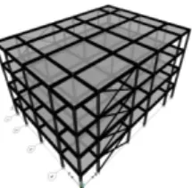
the finite element models are analyzed without column loss (external frame). In the second state, a corner column is removed on the ground floor. In the third state, a middle column is removed in the external frame. In the fourth state, the finite element models are analyzed without column loss (internal frame). And in the fifth state, a middle column is removed in the internal frame. It must be noted that the states are given in Table 4 and Figure 5.
Table 4. Introduction of states without column loss
State Frame position Column position
First External Without column loss
Second External A1 (ground floor)
Third External D1 (ground floor)
Fourth Internal Without column loss
Fifth Internal D2 (Ground floor)
Figure 5. Position of column losses
2.3. Loading
Loading on entire spans is according to the equation below. (1)
𝐺
𝑁=
𝛺
𝑁(
1.2𝐷𝐿
+
𝑜,5𝐿𝐿
) + 0.002
∑
𝐷𝐿
+
𝐿𝐿
where
𝐿𝐿
and𝐷𝐿
are the live and dead loads, respectively, is the lateral load assumed for each0.002
∑
𝐷𝐿
+
𝐿𝐿
story and separately applied to 4 sides of the building,
𝐺
𝑛is the gravity load for the whole structure and
𝛺
𝑁 is the column loss factor calculated according to the UFC 4-23-03 using Equations 2-4.(2)
𝛺
𝑁= 1.08 + 0.76
(
𝜃
𝑝𝑟𝑎𝜃
𝑦
+ 0.83
)
3. RESULTS AND DISCUSSION
3.1. Criteria for axial force of columns
When the columns are removed in different states, the load is distributed among adjacent members; these members should be able to withstand additional forces. Hence it is possible to observe the distribution of forces in the members before and after column by monitoring the axial forces in columns adjacent to the position of removed column. It is worth mentioning that due to the seismic design of all sections and no interference of seismic loadings during progressive collapse, other columns can still possess the capacity to bear the applied load even in case of removal of some main load bearing members. Subsequently, the percentage of axial force changes in columns in the frames of 4-, 8- and 10-story buildings are listed in Figure 6 and Figure 8.
Figure 6. Axial force changes for loss of column D1
Figure 7. Axial force changes for loss of column A1
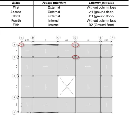
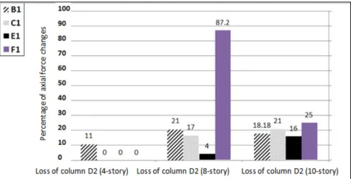
Figure 8. Axial force changes for loss of column D2
As illustrated in Figure 6, when the column D1 (third state) is removed, the column F1 located at the corner of the building is exposed to the maximum axial force changes. For the loss of column A1 which is a corner column, just the axial force of column B1 changes; so that the column (B1) helps to prevent progressive collapse in the structure during the loss of column A1. However, a reason why the axial force changes of columns C1, E1 and F1 equal zero is a cross bracing in the span BC; in other words, the presence of bracing can help the redistribution of forces in the members adjacent to the position of removed column.
Figure 8 shows the percentage of axial force changes for the loss of column D2. In fact, D2 is a middle column in the internal frame of structure. As observed, when a column is removed from the internal frame of structure, the columns around the removed column undergo far more changes compared to the previous state (column loss in the external frame), so that even the axial force reaches 2.6 times the initial value in some columns (e.g. column C1). In the assessment of potential of progressive collapse in the structure, it can be thus concluded that the column loss in internal frames shows a more critical condition of
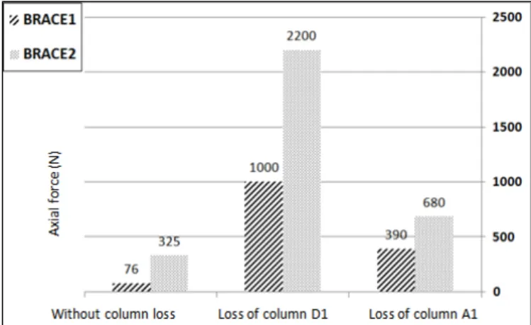
3.2. Criteria for axial force of braces
Investigating Figure 9, Figure 10 and Figure 11 and comparing the second and third states, the impact of bracing on the redistribution of axial forces after the processes of column loss becomes clear. Obviously, when
braces in comparison with the corner column loss; so the loss of middle column must be particularly noticed when evaluating the potential of progressive collapse in a structure for the design of bracing. It must be noted that this is true for all three 4-, 8- and 10-story frames.
Figure 9. Comparison of forces produced in braces for 4-story building
Figure 10. Comparison of forces produced in braces for 8-story building
3.3. Resistance criterion
An acceptance criterion for the alternative load path is the demand/capacity ratio (DCR) described in form of Equation 3.
(3)
𝐷𝐶𝑅
=
𝑄
𝑈𝐷𝑄
𝑈𝐶is the force calculated by the analysis of a member or
𝑄
𝑈𝐷connection and
𝑄
𝑈𝐶 is the expected capacity for a member or connection.DCR values are calculated for the critical beams of studied models and shown in form of a chart in Figure 12. Evidently, the DCR values are less than 2 for all beams, so all of them are within ranges determined in the codes.
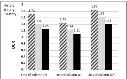
Figure 12. Comparison of DCR values for beams in second, third and fifth states
A Comparison of DCR values for the beams in the second, third and fifth states suggests that the fifth state (loss of column D2) is a more critical condition for the evaluation of potential of progressive collapse in the structure in comparison with the loss of an external column. A comparison of second state (loss of column A1) and third state (loss of column D1) also show that DCR values for the third state are higher than those for the second state. Accordingly, it can be concluded that the progressive collapse resistance of the structure for the loss of an internal column from the external frame is lower than that for the loss of a corner column. Another result obtained from the chart in Figure 7 is that DCR values decrease as the floor height increases; it means that as the floor height
increases, the potential of progressive collapse declines in the structure.
3.5. Displacement criterion
Figure 13 presents the maximum displacements at the
position of column loss in the second, third and fifth states for the 4-, 8- and 10-story buildings. As observed in most states, the displacements at the position of column loss for the 4-story building are more than those for the 8- and 10-story buildings. This means that as the height increases, the displacement at the position of column loss decreases. Therefore, it can be concluded that as the height increases, the potential of progressive collapse declines in the structure.
Figure 13. Comparison of displacements at position of column loss in different states
3.4. Control of criteria for displacement of members
The hinge rotation (θ) is another criterion of the member’s
response, which makes the maximum displacement response a function of the length of member’s span and
μ θp μ θp μ θp
1.102 0.0113 1.48 0.012 1.906 0.0117 4
0.731 0.0211 1.006 0.0193 1.504 0.0155 8
1.237 0.0294 1.697 0.0143 1.697 0.0346 10
4. CONCLUSION
Given the deformed model of systems, the following results are obtained after the convergence in the analysis process.
The results of analyses suggest that the loss of middle columns in braced frames is more critical than the loss of corner columns. In other words, the central columns of perimeter frame are more vulnerable than the corner columns.
The columns connected to the removed column by beams have the highest contribution towards the redistribution of forces in the structure. Meanwhile, the effect of adjacent columns is more than that of other columns and it seems that the additional capacity of columns adjacent to the removed column plays a key role in the prevention of progressive collapse.
Investigating the resistance criterion in the structure, it is found that the calculated DCR values are far less than the allowable range of GSA due to the relatively strong seismic design of members and short spans in conventional steel structures in Iran.
Although the satisfaction of all criteria of the GSA in this particular structure and the success of Iranian National Building Code, Part 6 and Part 10 and Iranian Code of Practice for Seismic Resistant Design Buildings (Standard No. 2800) are revealed in the prevention of progressive collapse, the evaluation of effect of irregularities across the plan and height, longer beam spans and more number of stories still require further research and a considerable change in these parameters probably results in a progressive collapse in the structures.
Braced steel frames are less vulnerable to progressive collapse caused by the combination of lateral and gravity loads, compared to the studied moment frames.
The displacement at the position of column losses in the 4-story building is more than that of the 8-story building and the value for the 8-8-story building is more than that of the 10-story building. It means that as the height increases, the displacement at the position of column loss declines. So it can be concluded that as the height
increases, the potential of progressive collapse decreases in the structure.
A comparison of DCR values of the beams in the second, third and fifth states suggests that the fifth state (loss of column D2) is a more critical condition for the evaluation of potential of progressive collapse in the structure, compared to the loss of an external column. A comparison of the second state (loss of column A1) and the third state (loss of column D1) also shows that DCR values of the third state are higher than those of the second state. Hence it can be concluded that the progressive collapse resistance of the structure for a middle column loss in the external frame is lower than that for a corner column loss.
DCR values decrease as the floor height increases; this means that as the height increases, the potential of progressive collapse declines in the structure.
A comparison of the second state (loss of column A1) and the third state (loss of column D1) indicates the effect of bracing on the redistribution of axial forces after the processes of column loss. As observed, when the column A1 next to the braced span is removed, the axial force produced in braces is far less than that for the loss of column D1. In other words, when a middle column is removed, more axial force is generated in braces compared to that for the loss of a corner column. This reveals that the loss of a middle column lead to a more critical condition in braces in comparison with the loss of a corner column; thus, the loss of a middle column should be highly noticed when evaluating the potential of progressive collapse in a structure for the design of braces. It should be noted that this is true for the whole three 4-, 8- and 10-story frames.
FUNDING/SUPPORT
Not mentioned any Funding/Support by authors.
ACKNOWLEDGMENT
AUTHORS CONTRIBUTION
This work was carried out in collaboration among all authors.
CONFLICT OF INTEREST
The author (s) declared no potential conflicts of interests with respect to the authorship and/or publication of this paper.
REFERENCES
1. Saad A, Said A, Tian Y, editors. Overview of progressive collapse analysis and retrofit techniques. The Proceedings of the 5th International Engineering and Construction Conference (IECC; 2008.
2. Alashker Y, El-Tawil S. A design-oriented model for the collapse resistance of composite floors subjected to column loss. Journal of Constructional Steel Research. 2011;67(1):84-92.
3. Ellingwood BR, Smilowitz R, Dusenberry DO, Duthinh D, Lew HS, Carino NJ. Best practices for reducing the potential for progressive collapse in buildings. 2007.
4. Park J, Kim J. Fragility analysis of steel moment frames with various seismic connections subjected to sudden loss of a column. Engineering Structures. 2010;32(6):1547-55.
5. Kim J, Kim T. Assessment of progressive collapse-resisting capacity of steel moment frames. Journal of Constructional Steel Research. 2009;65(1):169-79.
6. Khandelwal K, El-Tawil S, Sadek F. Progressive collapse analysis of seismically designed steel braced frames. Journal of Constructional Steel Research. 2009;65(3):699-708.
7. Kim H-S, Kim J, An D-W. Development of integrated system for progressive collapse analysis of building structures considering dynamic effects. Advances in Engineering Software. 2009;40(1):1-8.
8. Fu F. Progressive collapse analysis of high-rise building with 3-D finite element modeling method. Journal of Constructional Steel Research. 2009;65(6):1269-78.
9. Asgarian B, Rezvani FH. Progressive collapse analysis of concentrically braced frames through EPCA algorithm. Journal of Constructional Steel Research. 2012;70:127-36.
10. Chen J, Huang X, Ma R, He M. Experimental study on the progressive collapse resistance of a two-story steel moment frame. Journal of Performance of Constructed Facilities. 2011;26(5):567-75.
11. Chen J, Peng W, Ma R, He M. Strengthening of horizontal bracing on progressive collapse resistance of multistory steel moment frame. Journal of Performance of Constructed Facilities. 2011;26(5):720-4.
12. Gerasimidis S. Analytical assessment of steel frames progressive collapse vulnerability to corner column loss. Journal of Constructional Steel Research. 2014;95:1-9.
13. Tavakoli H, Alashti AR. Evaluation of progressive collapse potential of multi-story moment resisting steel frame buildings under lateral loading. Scientia Iranica. 2013;20(1):77-86.
14. Hosseini M, Fanaie N, Yousefi AM. Studying the vulnerability of steel moment resistant frames subjected to progressive collapse. Indian Journal of Science and Technology. 2014;7(3):335.
15. Yousefi AM, Hosseini M, Fanaie N. Vulnerability assessment of progressive collapse of steel moment resistant frames. Trends in Applied Sciences Research. 2014;9(8):450.
16. NIST. Best practices for reducing the potential for progressive collapse in buildings. Technology administration, US Department of Commerce, National Institute of …; 2007.