Journal of Civil Engineering and Materials Application
Journal home page:
http://journals.rpp.co.ir/jcemaReceived: 26 February 2018 • Accepted: 27 April 2018
Research
doi:10.xxxxx/J.JCEMA.12020205
Experimental Study on the Effect of Single Spur-dike
with Slope Sides on Local Scour Pattern
Hamed Haghnazar1*, Behnoush Hashemzadeh Ansar2, Farzin Asadzadeh3, Seyed Ali Akbar Salehi Neyshabouri4
1 Department of Civil Engineering, Islamic Azad University of Shahr-e-Qods, Tehran, Iran 2 Department of Civil Engineering, Shomal University, Amol, Iran
3 Department of Civil Engineering, Tarbiat Modares University, Tehran, Iran 4 Water Engineering Research Institute, Tarbiat Modares University, Tehran, Iran
*Correspondence should be addressed to Hamed Haghnazar, Department of Civil Engineering, Islamic Azad University of Shahr-e-Qods, Tehran, Iran; Tel: +989128451247; Fax: +9888853153; Email: [email protected].
ABSTRACT
Constructing the spur-dikes is one the most efficient methods for protecting river banks. The spur-dike in the flow path leads to local scour around this structure. Scour around the spur-dike is one the major problems that might endanger the stability of the structure. Therefore, estimating the scour around this structure based on the flow condition and geometry of the spur-dike is highly important. The experiment was conducted in laboratory flume 6m long, 0.45 m width and 0.45 m deep and with median diameter of particle size 1.48 mm and the maximum local scour around the direct upright and trapezoidal spur-dike (with slope side) and the effect of Froude number and spur-dike side slope on geometry of local scour are investigated. According to the results, by increasing the Froude number and spur-dike side slope, the maximum scour depth and hole dimension of scour is increased, also sedimentation length is increased but its height is decreased and the amount of bed changes toward downstream is increased.
Key words: Spur-dike, Slope side, Scour, Froude number.
Copyright © 2018 Hamed Haghnazar et al. This is an open access paper distributed under the Creative Commons Attribution License.
Journal of Civil Engineering and Materials Applicationis published byRaika Pajuhesh Pars; Journal p-ISSN xxxx-xxxx; Journal e-ISSN 2588-2880.
1. INTRODUCTION
he spur-dikes are deflector structure that are developed from the river banks towards the flow center and leads to deviation and directs the flow from the banks towards the river centerline. This flow deviation creates rotating area with severe turbulence around the spur-dike. Hydraulic process of this matter expands the scour hole around the spur-dike and bed material sedimentation in downstream and the river bank. While the scour is considered as a serious hazard for the spur-dike and consequently for the river, sedimentation in downstream river banks is a natural solution for protecting the river banks. The spur-dike in flow path causes local
dike nose and by increasing the flow it moves towards the
center of the channel (1). Ghodsian and Tehrani (2001)
conducted a research on investigation of position and
length of the spur-dike on its scour in 90O bend. The results
showed that the maximum scour depth of the first half of the bed is less than that of the second half bend. Opposite of the maximum scour depth, dimensions of the scour hole increases by moving the spur-dike from the first half of the
bed to its second half (2). Nagy (2004, 2005) by studying
the spur-dike angle with the bank and Froude number for submerged and non-submerged spur-dike in direct channel, reached to the conclusion that the scour increases by
raising the Froude number and also the scour for 90⁰ is
(2009) investigated an experimental and numerical study to simulate the flow pattern and bed alternation in presence of permeable and impermeable spur-dike. These experiments have been conducted in direct flume 8 m long, 0.4 m wide and 0.4 m deep in clear water condition. This research showed that permeability has an important effect on flow pattern and bed changes. Results showed that in a permeable spur-dike due to the flow separation and formation of vortexes, the scour occurs between the shafts while in impermeable scour due to flow separation and formation of horseshoe vortexes, scour occurs behind the
spur-dike (8). Masjedi et al, (2011) conducted a laboratory
research on a scour around L-shaped spur-dike in 180⁰
bend in clear water condition. They performed their tests by Fr=0.23, 0.25 and 0.35. The spur-dike with the length of 10, 15, 20 and 25 percent of channel width were settled
in 30⁰, 45⁰, 60⁰ and 90⁰ in bend. The obtained results
showed that the depth of scour increases by passage of time. The scour depth increases by raising Froude number. Increasing the length of spur-dike raises the maximum
depth of the scour (9). Teraguchi et al, (2011) used a
laboratory model for investigation of turbulent flow and bed changes around permeable and impermeable spur-dikes. Results of the tests showed that the maximum scour depth in impermeable spur-dike nose is more than that of
permeable spur-dike (10). Osman and Negmaldin (2012)
locating spur-dikes. Their research showed a slow velocity area between the spur-dikes in which the sedimentation occurs. By increasing the distance between the spur-dikes, the flow velocity between them increases and this matter lead to changes the sedimentation pattern between the
spur-dikes (12). By considering the studies of the previous
researches, it is found that few number of researches have been done on the shape and geometry of the structure, scour hole expansion and scour pattern around spur-dikes. One practical and economical method is to construct spur-dike by using Rip Rap and therefor the spur-spur-dikes are often built in trapezoidal shaped. In this research, the maximum of local scour in erodible bed around direct upright and trapezoidal (with slope sides) spur-dike were studied. By doing this research for different side slopes and also diverse hydraulic condition, besides comparing the result of upright spur-dike, the effect of side slopes on the erosion around the spur-dike can be found out.
2. MATERIALS AND METHODS
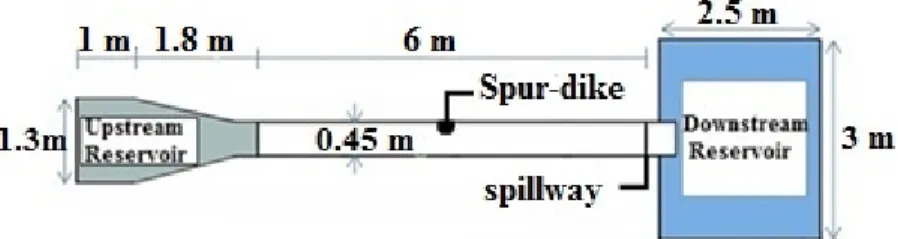
The experiments were conducted in a laboratory flume 6 m long, 0.45 m wide and 0.45 m deep in the hydraulic laboratory of Tarbiat Modares University. The walls and the bottom of the channel are made of glass which is 10 mm thick. The bed material is sand with d50=1.48 mm. The
Channel’s characteristics have been shown in Figure 1.
Figure 1. Laboratory equipment and channels
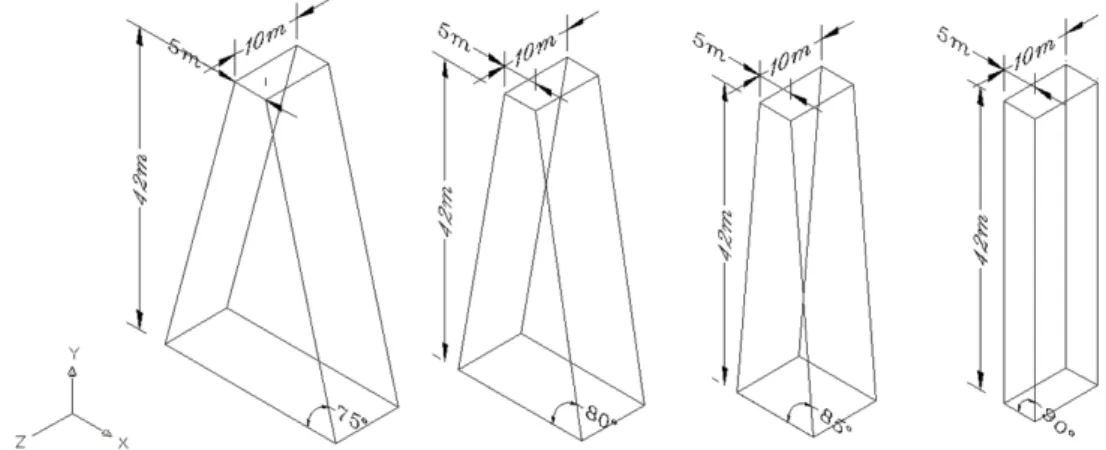
The utilized spur-dikes in the experiments are impermeable and made of Plexiglas. In this research four spur-dikes have been used which are 10 cm length, 5 cm width, 42
cm deep and the side slope are 90⁰, 85⁰, 80 and 75⁰.
Figure 2. A schematic view of the utilized spur-dike in the experiments
In order to find a relationship between the effective factors on the scour around the spur-dikes, a dimensional analysis was conducted on the influential parameters. The independent and effective variables are: Channel width (B), channel longitudinal slope (s0), spur-dike length (L), the
angle of spur-dike with wall (β), the spur-dike height (H),
the spur-dike width (b), the side slope of the spur-dike (z), the average flow velocity before the spur-dike (U), the flow depth in upstream (h), the average diameter of the bed material (d50), the standard deviation in distribution of the
particle size (σg), submerged density of the bed material
(ϒs), water mass density (ρ), sediments mass density (ρs),
acceleration of gravity (g), kinematic viscosity (ν). By
selection of maximum scour depth (dse) as the dependent variable, the following relation is obtained:
dse=f (B, S0, L, β, H, b, Z, U, h, d50, s, g, , ,s, , g,)
(1)
The general form of the above mentioned relation by
using -Buckingham Method could be written as follow: Π
𝑑𝑠𝑒
ℎ =𝑓( 𝐵 ℎ, 𝑆0,
𝐿 ℎ,𝜃,
𝐻 𝐿,
𝑏
ℎ, 𝑍,
𝑈 𝑔ℎ,
ℎ 𝑑50,
𝜌 𝜌𝑠,𝜎𝑔,
𝑈ℎ ,
𝜌 𝑈2 ∆𝛾𝑠𝑑50) (2)
Due to the channel slope, the angle of spur-dike with the wall, Fluid, length and depth of spur-dike are constant, the
dimensional parameters of 𝑆0, , , , 𝜃 𝐻𝐿 𝜌𝜌 , are removed.
𝑠 𝜎𝑔
Consequently by combining, the following dimensionless parameters are considered as follow for investigation of the variable effect on the scour around the spur-dike with slope side:
𝑑𝑠𝑒
ℎ =𝑓( 𝐹𝑟, 𝑅𝑒, 𝑍)
(3)
Due to the turbulence of the flow, the effect of Reynolds number can be ignored and ultimately the following equation is obtained:
𝑑𝑠𝑒
ℎ =𝑓( 𝐹𝑟,𝑍)
(4)
Discharge is constant for all the experiments in 15 l/s, and once the channel width and the flow depth is known, U can be calculated. In this way U/Uc is determined. Three flow depths were considered for the experiments and
consequently the ratio of U/Uc was obtained. Table 1
shows the flow condition in the experiments. By considering the three Froude number and four slope sides for the spur-dike, twelve experiments were conducted.
Table 1. Froude number and flow depths in the experiments
h (m) U (m/s) Uc (m/s) U/Uc Fr
0.11 0.303 0.355 0.85 0.29
0.12 0.278 0.367 0.76 0.26
0.13 0.256 0.377 0.68 0.23
At the beginning of the experiments, large amount of scour could be seen around the spur-dikes and gradually by passage of time the erosion process slowed and finally after a while it was balanced. In this research Ettema criteria was used. Ettema (1980) considered the relative
balance time for the scour hole in experiments equal to the time that the scour depth changes in each 4 hours be less
than 1 mm (13). In Figure 3, the balance time of one of the
test can be seen. Based on the figure and the calculation, 24 hours has been considered as the balance time.
Figure 3. The balance time of scour
In these experiments, after the channel drainage, changes in the bed around the spur-dikes after the scour and sedimentation were measured by a laser meter. Longitudinal grids for measuring have been irregular in a way that in the areas with more bed changes, smaller gridding is selected and in the areas where the topography was flatter, bigger gridding was used. The minimum and maximum distance between the longitudinal grids along the channel were respectively 2 cm and 10 cm. The
distance between measured points in latitudinal grids was 1.5 cm.
3. RESULTS AND DISCUSSION
In this research, different parameters of scour geometry were studied. The defined parameters are: upstream length of scour hole (a), downstream length of the scour hole (b),
scour hole width (c), maximum scour depth (ds) (Figure 4).
Figure 4. The scour hole dimension
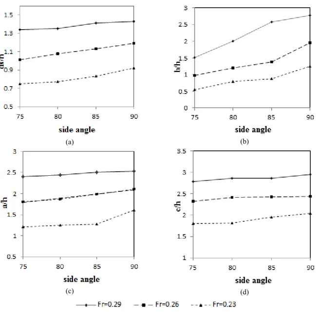
In order to investigate the effect of the spur-dike slope sides on the maximum scour depth, the scour hole width and the scour hole upstream and downstream length, above mentioned experiments were conducted in U/Uc=0.68, 0.78
and 0.85. In Figure 5 the effect of slope on these
parameters can be seen. According to Figure 5 (a), by
increasing the spur-dike side slope from 75⁰ to 90⁰, the
maximum scour depth increases. Since by increasing the dike side slope, vortex power in upstream of spur-dike increases and this increase eases the material erosion of the spur-dike upstream and also the capacity of sediment transport inside the scour hole increases. In addition, the maximum scour depth occurs in upstream of spur-dike
nose. In Figure 5 (b), changes of the downstream length of
scour hole have been shown. By decreasing the spur-dike
also decreased because by reducing the spur-dike side slope, the spur-dike width is increased and the vortex is formed and moved from the upstream of spur-dike nose, should pass a long distance for sediment transport from spur-dike to downstream and this matter leads to reduction of sediment transport power to downstream and consequently decrease the downstream length of scour hole.
Figure 5 (c), by increasing the spur-dike sides slope in all
conditions, upstream length of the scour hole increases because by increasing the scour hole depth, material collapse from the hole side increases and this matter leads
to growth of scour hole length in upstream. In Figure 5 (d)
by increasing the spur-dike side slope, the scour hole width increases and this is caused by the scour depth growth due to the slope increase.
(a) (b)
(c) (d)
Figure 5. The scour hole parameters change in diverse spur-dike sides slope: a) the maximum scour depth, b) the scour hole downstream length, c) the scour hole upstream length, d) the scour hole width
In Figure 6, longitudinal profile in 10% of the channel
width for Fr=0.26 has been shown. As it is seen, by increasing the spur-dike side slope, the scour depth in
upstream and downstream of the spur-dike is increased. Also by increasing the spur-dike sides’ slope, bed change and migration towards downstream becomes more.
(a) (b)
(c) (d)
Figure 7. Bed topography changes for Fr=0.26 a) spur-dike with 75⁰ side slope, b) spur-dike with 80⁰ side slope, c) spur-dike with 85⁰ side slope, d) spur-dike with 90⁰ side slope (flow is from right to left)
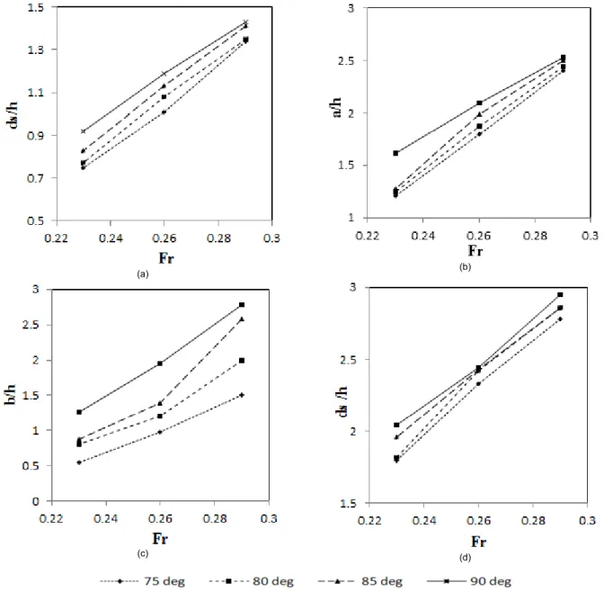
In Fig.8 The effect of the Froude number on downstream length of the scour hole, maximum scour hole width and upstream length of the scour hole are seen. These experiments were conducted in four modes of spur-dike
sides’ slope. As it is shown in Figure 8 (a), by increasing
Froude number, the maximum scour depth in scour with different slope always increases and it is caused by increase of the flow velocity. By increasing the Froude number in a constant side slope, downward flow and horseshoe vortex work more appropriately in order to
increase the maximum scour depth. In Figure 8 (b), the
upstream length changes of scour hole in diverse slopes and three Froude number are seen. According to this figure, for all slopes of the spur-dike by increasing the Froude number, upstream length of scour hole is increased. When the Froude number of the flow in constant discharge increases, by increasing the flow velocity and decreasing the flow depth and increasing the downstream flow power, before the spur-dike bigger vortex formed. Therefore, the flow effect on the spur-dike upstream bed expands to
depends on the scour in the hole center so that the materials collapsed from the hole wall and transferred to the downstream with the channel main flow due to the vortex caused by pressure difference. Therefore, it brings about many changes of the scour hole upstream length
compared to the Froude number. In Figure 8 (c) the effect
of Froude number on alternations of the scour hole downstream length in different slopes of the spur-dike has been shown. By increasing the Froude number, the downstream length of the scour hole is increased, because by increasing the Froude number, sediment transport power is increased. In the spur-dikes with steeper slopes, this parameter alternation is more than Froude number. In
Figure 8 (d), in lower Froude numbers, due to the low
speed of the flow in the spur-dike upstream, the local effect of the flow on the width of the scour hole is little. By increasing the Froude number, the flow speed is increased and its depth is decreased and this matter increases the effects of velocity on the width of the scour hole and consequently by increasing the Froude number of the flow,
(a) (b)
(c) (d)
Figure 8. The scour hole parameters changes with different Froude number a) maximum scour depth, b) the scour hole downstream length, c) the scour hole upstream length, d) the scour hole width
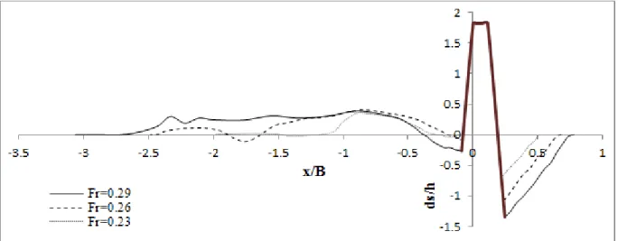
In Figure 9 and Figure 10, longitudinal profile in 10% of
the channel width for the spur-dike with 80 and 90 slopes has been shown. As it is seen, by increasing Froude
number, the scour depth flow in upstream and downstream of the spur-dike is increased and by increasing the Froude number length of the first sedimentation is increased.
Figure 10. Longitudinal profile in 10% of the channel width for the spur-dike with 80 side slope
In Figure 11 and Figure 12 the bed topography for two
spur-dikes with 75 and 90 side slope has been shown. According to the figure it can be concluded that by increasing the Froude number, the maximum scour depth and dimensions of the scour hole is increased. In addition,
length of the sedimentation after the spur-dike is increased. By increasing the Froude number, expansion of the bed surface changes towards downstream increases and the height of the sedimentary hill decreases.
(a) (b)
(c)
(a) (b)
(c)
Figure 12. Bed topography changes for 75 spur-dike, a) Fr = 0.29, b) Fr=0.26, c) Fr=0.23
On the whole it can be concluded that in direct spur-dikes with the slope sides in different Froude numbers, by increasing the Froude number and when the spur-dikes side slope gets steeper, the maximum scour depth and dimension of scour hole is increased. Also by increasing Froude number and the spur-dike sides slope, the sedimentation length is increased but its height decreases and expansion of bed changes towards downstream increases.
4. CONCLUSION
In this study, the maximum of local scour around the direct upright spur-dikes and trapezoidal spur-dike (with slope sides) have been studied and the effect of Froude number and the spur-dike side slope on the scour geometry provided. Results show:
1. By increasing the spur-dike side slope from 75 to 90 degree, the maximum scour is increased because by increasing the dike slope, the vortex power in spur-dike upstream is increased and the sediment transport power in the scour hole is increased.
2. By decreasing the spur-dike sides’ slope, also the scour hole downstream length decreases because by decreasing the spur-dike side slope, its width increases and it leads to the vortex energy reduction and it caused the reduction of the sediment transport power to downstream.
3. By increasing the spur-dike sides slope in all forms, the upstream length of the scour hole increases, because by increasing the scour hole depth, the material collapse from
and its main reason is increase of the flow velocity.
6. For all the spur-dike sides slope, by increasing the Froude number the scour hole upstream length increases because by increasing the flow velocity the downward flow power and the vortexes close to the spur-dike increases.
7. By increasing the Froude number, the downstream length of the scour hole is increased because by increasing the Froude number, the sediment transport power is increased. In the spur-dike with steeper slope, this parameter changes is more than that of Froude number. 8. In lower Froude numbers due to low velocity of the flow in upstream of spur-dike, the local effects of the flow on the scour width is little. By increasing the Froude number, the flow velocity increases and it leads to the scour hole width increase.
FUNDING/SUPPORT
Not mentioned any Funding/Support by authors.
ACKNOWLEDGMENT
Not mentioned any acknowledgment by authors.
AUTHORS CONTRIBUTION
This work was carried out in collaboration among all authors.
CONFLICT OF INTEREST
The author (s) declared no potential conflicts of interests with respect to the authorship and/or publication of this paper.