···
203
Journal of Civil Engineering and Materials Application
/ http://jcema.com
:
page
Journal home
Received: 29 July 2019 • Accepted: 23 November 2019
doi: 10.22034/jcema.2019.101787
Studying the Buckling Behavior of Composite
Columns (CFST) by Cyclic Loading
Seyed Ali Mousavi Davoudi
*1, Morteza Naghipour
21 Department of Structural Engineering, Faculty of Engineering and Civil Engineering, Tabari Higher Education Center, Babol, Ir an. 2 Professor, Faculty of Engineering, Noshirvani University of Technology, Babol, Iran.
Correspondence should be addressed to Seyed Ali Mousavi Davoudi, Department of Structural Engineering, Faculty of Engineering and Civil Engineering, Tabari Higher Education Center, Babol, Iran. Tel:+989112135016; Fax:+981132662426 Email: [email protected]
Copyright © 2019 Seyed Ali Mousavi Davoudi This is an open access paper distributed under the Creative Commons Attribution License. Journal of Civil Engineering and Materials Application is published by Pendar pub; Journal p-ISSN 2676-232X; Journal e-ISSN 2588-2880.
1. INTRODUCTION
he use of concrete-filled steel tubular columns (CFT) has become widespread in construction work, because of high earthquake resistance, high ductility, and high energy absorption capacity. The confinement created by the steel tube improves the concrete properties by creating triaxial tension And prevents the internal buckling of the steel tube [1]. In 1967, studies by Jacob Sen and Gardner showed that at low strains, the Poisson's ratio of concrete was in the range of 0.15 to 0.25, But for larger strains, Poisson's ratio of concrete reaches even about 0.6. As a result, Poisson's ratio for concrete is lower than steel in the initial stages of loading. Therefore, the steel tube has no confining effect on the concrete core, when the longitudinal strain
increases, the lateral strain of concrete will be greater than steel. So, a radial pressure Will be created. At the contact, surface of steel and concrete. In this situation, the concrete core is under triaxial stress and the steel tube is under tensile stress. Due to the cyclic tensile stress, the steel tube cannot withstand the normal yield stress, in this condition, the load transfer from the steel tube to the concrete core will occur, In composite columns, when the collapse occurs, due to the confinement effect of the concrete, the load proportionally to the failure is substantially larger than the sum of the concrete and steel collapse loads. in addition to the confinement effect of the core concrete, this load also depends on the factors:steel tube thickness, slenderness ratio, eccentricity load, and cross-section
T
ABSTRACT
One of the most sensitive decisions a structural designer should consider is choosing the type of consumables in the structure. This decision is in many cases dependent on the type of structure, financial issues also the experience and skill of the designer. The main aim pursued in the design is to obtain highly secure, economical structures. Concrete and steel are materials that are widely used in construction. The benefits of both materials are well known today. The clever combination of these two materials, an effective explosion-proof system, will have the effect of exploding explosions in the Plasco building in Tehran compared to using any of the materials. Lack of efficient performance factors, lack of clear and valid guidelines for the seismic design of such columns, how to model their geometry and material can still be obstacles to using such systems. In this research, according to the objectives of the problem, different parameters should be evaluated, this parameter is the type of column cross-section geometry. The aim is to determine the effect of defined parameters, especially column geometry, on the behavior and seismic capacity of composite columns )CFST(, achieving high resistivity, especially for columns that, incidentally, increase their loading exponentially with increasing classes. It is found that circular sections of composite columns )CFST( show better behavior and performance than columns with square geometry and further show that composite columns )CFST( can be used as a basic solution. Use it to solve challenges between designers and architects.
···
204 shape, In circular sections, the steel tube has a more confining effect than square sections. The corners of the square sections are under a larger confining pressure than the center part, but in circular columns, the confining pressure is uniformly distributed, and the performance of CFT columns under continuous loading is also different from reinforced concrete columns [2-5]. In reinforced concrete columns, concrete experiences shortening at initial age. and it continues whit prolonged periods of contraction and, creep under load. But in the CFT columns, due to the humid environment inside the steel pipe, the shortening coefficient is low and the contraction will be very slow. The behavior of CFT columns under the effect of axial concentrated load depends on the buckling length(
L
e), Minimum cross-section size (B),and mechanical properties of concrete and steel. The slenderness ratio can be calculated by the relation
r
L
e
orB Le, which is a short, medium or long (thin) column. The mechanism of failure of the short
-
columns is associated with the yielding of the steel tube and the crushing of the concrete. Medium composite columns have non-elastic behavior. Moreover, their failure mechanism is by the yielding of the steel tube and the crushing of the concrete under pressure and cracking of the concrete in tension. The long columns behave elastically and their method of analysis is elastic. In this condition, the initial deformations are ignored. And the behavior of the column is proposed according to the Euler curve.
One of the parameters that influence the behavior of the enclosed concrete column is the shape of the column cross-section. The compressive stress distribution with confinement in rectangular cross-sections is non-uniform, but the compressive stress confined to circular sections is quite uniform. The reason for the non-uniform lateral pressure distribution in square and rectangular sections is that,Due to the expansion of concrete, cross-sections undergo (in-plane bending stress) and (in-plane bending deformation). This deformation causes the lateral pressure in the center of the sides to be the lowest. But in the circular sections, there is no bending in the membrane and it is only stretched [6]. The uniform pressure distribution in circular sections causes the entire core concrete to be completely enclosed. But in rectangular sections, only part of the cross-section is effectively enclosed. So result, enclosed circular sections will perform better. By increasing corner radius the confined area of core concrete increases in square and rectangular sections [7].Australian codes AS4100 and AS360 are for concrete and steel structures respectively. And similar to the ACI318 code, they do not consider the confinement effect. And provide a similar relationship to that proposedin ACI318 for compressive strength of confined concrete. So their results are very conservative. The AS360 code assumes a value of 0.85 for the capacity reduction factor of concrete (C2) This Code specifies the sample size, sampling method, processing method and long-term loading effects in calculating the compressive strength of concrete. This Code considers the sample size, sampling method, processing method and long-term loading effects in calculating the compressive strength of concrete. Giakamulis et al based on the experimental results proposed a coefficient for the ACI / AS code equations. By applying this coefficient, the effect of concrete confinement on the axial load capacity of a steel tube filled with CFT concrete was considered. They presented the modified equation
N
U
1
.
3
A
cF
c
A
sf
y, where (As) steel tube cross-
section, (Fy) (steel yield stress); (Ac) core concrete area; (Fc) concrete compressive strength [8]. Guan et al. (2019) examined the behavior of concrete-filled steel columns (CFT) by valid world codes and compared them with finite element results. In this study, they showed that placing concrete under multiaxial pressures increases concrete strength and ductility. This is due to the prevention of the expansion of lateral strains of concrete. One way to create multi-axial pressure is to enclose the concrete core with a steel tube. Using ACI-318, EC-4, CSA, and AISC codes, they investigated the compressive strength of steel columns filled with CFT concrete based on parameters: diameter ratio to the thickness of steel tube, the compressive strength of concrete and steel yield stress. And compared the results with those obtained from the finite element method. Finally, it was found that the EC-4 code was closer to the finite element results than the other codes [9].Naghipour et al. (2018) conducted a study on buckling in composite columns (CFTs), in which they stated that one of the composite columns is the concrete-filled steel column (CFT). The system consists of concrete as the inner steel core as the outer wall. The subject of buckling in pressurized columns is one of the most commonly used topics. The buckling in these columns exhibits both general buckling and local buckling. In this study, the buckling rate in the columns is shown as both general buckling and local buckling. In this research, the buckling rate of CFT columns under different support conditions is investigated and then buckling and its related relationships are investigated using internationally valid regulations [10]. Hwang et al., Conducted a research on finite element analysis of circular CFT columns with consideration of the slip-coupling effect: they performed a final strength evaluation; The design approach is based on two steps: constructing a linear PM interaction diagram for a circular column cross section and modifying it according to the weight ratio. To construct
the P-M linear interaction diagram of circular CFT columns without a detailed nonlinear analysis, simple
equations are presented in this paper. Then, based on the numerical results obtained using the analytical model presented in the previous paper, the final resistive
···
205 capacitance reduction coefficients were designed through a linear curve regression that utilized these coefficients to determine the ultimate capacitance of thin CFT columns without any analysis. Ensures accurate nonlinearity. Finally, the performance of the proposed design equation is validated by comparing the final resistive capacitance calculated in this paper with the values determined by accurate nonlinear analysis and by the AISC and Eurocode design guidelines [11]. Murtaza et al (2013), conducted an experimental study on hollow steel columns filled with lightweight concrete under reciprocating loads. They used three different degrees of lightweight concrete for testing and examined the samples with and without fiberglass coating. The final bearing capacity of the columns and their length reduction were some of the parameters that were investigated. CFT column height, cross-section, and thickness were also evaluated. According to the results of this study, cross-sectional area has the greatest impact on the final bearing capacity of the CFT column and increases the column length, reducing its bearing capacity [12]. Ghannam et al. (2015) conducted experiments on CFT columns with lightweight concrete and plain concrete. Eight rectangular cross-section and full-scale test specimens, four with lightweight concrete and four with plain concrete, were tested to verify the actual behavior and bearing capacity of these CFT columns. The results of this experiment showed that the CFT columns had acceptable performance and failure times of all samples were higher than the final design load. According to this experiment, CFT columns with ordinary concrete can withstand 1.5 times more load. In contrast, lightweight concrete CFT columns are 5 to 5 percent lighter in weight. Also, the behavior of lightweight concrete columns and ordinary concrete columns is very similar. Normal concrete CFT columns were fractured due to general buckling in the middle of the cradle, whereas in CFT columns with light concrete first local buckling occurred and then general buckling occurred [13].The earliest studies on composite columns by Bur in the year 1912 have since been followed by many studies and experiments with different theoretical implications. Reinforcement of steel wall columns using sheets was performed experimentally for the first time in the year 1990 and experiments showed significant bearing capacity and significant seismicity, so this technology is widely used, especially in seismic applications. In recent years, numerous articles have been published on the technology of composite columns filled with concrete. The results show that more laboratory investigations are needed for high strength concrete composite columns (HSCs) [14]. Among the experimental and experimental studies, Johnsson et al. Have shown that it is possible to use high strength concrete and to create instrumentation in the column. If the column is subjected to a centrifugal force, it is obvious
that the strain level of the column cross-section increases and the curvature increases to the concrete strength and the damper effects [15]. Oshea and Bridge in year 2000 showed that increasing the excitation of the center of force improves the shape of the short columns. Of course, these theories about thin columns had to be reinforced, and there was not much research on CFT columns or efficient materials, which focus on the buckling of global columns [16]. Han et al. (2000) have conducted studies on composite columns or high slip but normal strength composites (NSCs) and have shown that concrete strength has very little impact on the final capacity of these columns [17]. Sheikh et al and Mander et al conducted research on reinforced concrete columns, showing that the concrete column is divided by reinforcement reinforces into two parts. One is the inner effective concrete encapsulated concrete core and the other non-effective external encapsulated concrete comprising cover concrete and the concrete portion between reinforcing bars. In steel composite columns, concrete enclosures are provided by steel sections and reinforcing bars, the concrete encapsulates many factors including steel cross section, diameter, grating, distance and number of longitudinal reinforcements, as well as diameter and distance. Depending on the transverse reinforcement, in addition the stress yielding factors of steel sections and reinforcing reinforcement, such as the compressive strength of concrete, are effective on the enclosure. The composite column is divided into three main sections based on confinement areas consisting of highly encapsulated concrete, partially encapsulated concrete, and non-encapsulated concrete [18,19]. Chen and Lin, using a similar approach to their analytical research using different forms of steel cross sections and different reinforcement mesh designs, investigates confinement factors for high-strength concrete and partially encapsulated concrete parts. The enclosure has been dealt with. Mirza et al. Have also shown in their research that the enclosed portions can be simplified by converting the parabolic section into a rectangular one [20,21]. Mursi and Yu, on 6 column specimens consisting of 4 thin-walled sheets with localized shear coefficients of sheets 40, 50, and 60 in concrete and non-concrete modes, in order to achieve the effect of high strength concrete on buckling capacity (local and overall) Concluded that all columns had relatively linear behavior before reaching the final load, and that the presence of high strength concrete in the composite samples increased the loading capacity of the column by about 2 to 3 times and gradually reduced the hardness, Maximum force has been applied [22,23]. Ellobody et al., In order to obtain the effect of structural yield stress (275-690 Mpa) on the load resistance of 12 concrete composite steel column specimens with effective lengths of 1,2,3 and 4 m, concluded, They found that increasing structural steel strength had little effect on high slenderness composite
strength due to flexural buckling mode, whereas the use of high strength steel in short columns significantly
increased composite strength [24]. Kute et al., By conducting experiments on circular and canister sections in concrete and non-concrete mode, in order to achieve
···
206 the load-bearing capacity of steel-filled concrete columns, concluded that filling hollow steel sections with Concrete prevents the internal buckling of the steel wall from cross-sectioning, thereby increasing the bearing capacity by delaying the local buckling phenomenon. Also, in circular sections the increase in the final capacity of the concrete due to entrapment is very significant, and the effect of concrete entrapment varies with respect to the
diameter-to-thickness ratio as well as to the length-to-diameter ratio [25]. Young Bong et al. 2016 conducted a study on the calculation of the bending force of concrete-filled pipe columns with local buckling, In this paper, they describe a series of compression tests on hollow steel cross-sections (CHS) and concrete-filled circular tubes (CFT). The diameter-to-thickness ratios in the test specimens vary from 45 to 140. This interval is adjusted to
investigate the effect of local buckling on the shell of circular steel specimens at the highest CFT column strength. The limiting effect of steel shell on the internal concrete has also been investigated in this study. In this study, a compressive force formula for CFT columns is presented to calculate the strength of the steel shell after local buckling. Also in this study, the ultimate strength of the steel shell was calculated using a direct resistance method (DSM). The proposed DSM formula does not need to calculate the effective area of the steel shell, but rather uses the total area of the steel shell and the design resistance formula based on the various test results. The
formula of the compressive strength of the inner concrete of these columns, which calculates the ratio of the strength of the steel shell to the concrete-filled part, is presented in this study to calculate the increase in the compressive strength of the inner concrete, which is due to the increase in compressive strength, The limiting effect is the steel shell. The resistances under the design of the CFT columns were compared with the test results to confirm the obtained values [26]. Due to the necessity of this research and studies, in this study we study the buckling behavior of composite columns (CFST) by cyclic loading.
2. MATERIALS AND METHODS
In this study, two groups A and B were used to investigate the mechanical behavior of composite columns by cyclic loading. All of these models will be modeled and
analyzed by the Abaqus6.14 program, in Table (1), the sample specifications are presented.
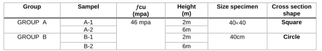
Table 1. Specifications of the analyzed cross sections
Cross section shape Size specimen Height (m) cu (mpa) Sampel Group Square 4040
2m 46 mpa
A-1 GROUP A
6m A-2 Circle 40cm 2m B-1
GROUP B
6m B-2
The specifications of the steel materials used in the modeling specimens are of ST37 steel, which is defined bilaterally in the Abaqus software. The mechanical
properties of the elastic and plastic ranges of the steel used are presented in Table (2).
Table 2. Mechanical Properties of Steel
Ultimate strain Stress yields (Mpa) Elastic modulus (Mpa) Poisson's ratio 0 370 200000 0.3 0.15 420
Concrete with a compressive strength of 46 MPa was defined by the model of Concrete Damage plasticity The boundary conditions of the specimens were applied under axial loading of 150,000 N. In the loading region, the specimen moves in the Y direction and is bounded in the X and Z transitional motion. (U2 0,
U
1
U
3
0
) And thesample can only rotate in the Z direction and is bound in the X and Y directions. The support in the X, Y and Z directions is bound by transitional and rotational motion.
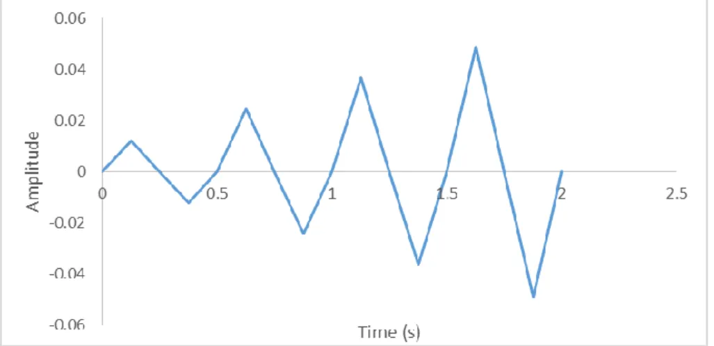
The Solid C3D8R element was used to model the concrete core of the CFT column, and the Shell element was used for modeling the steel tube section of the CFT column. For welded edges, the tie constraint was used, and the contact surface to surface was used to define the surface status of all the contacted plates. Figure 1 Shows the cyclic loading diagram.
···
207
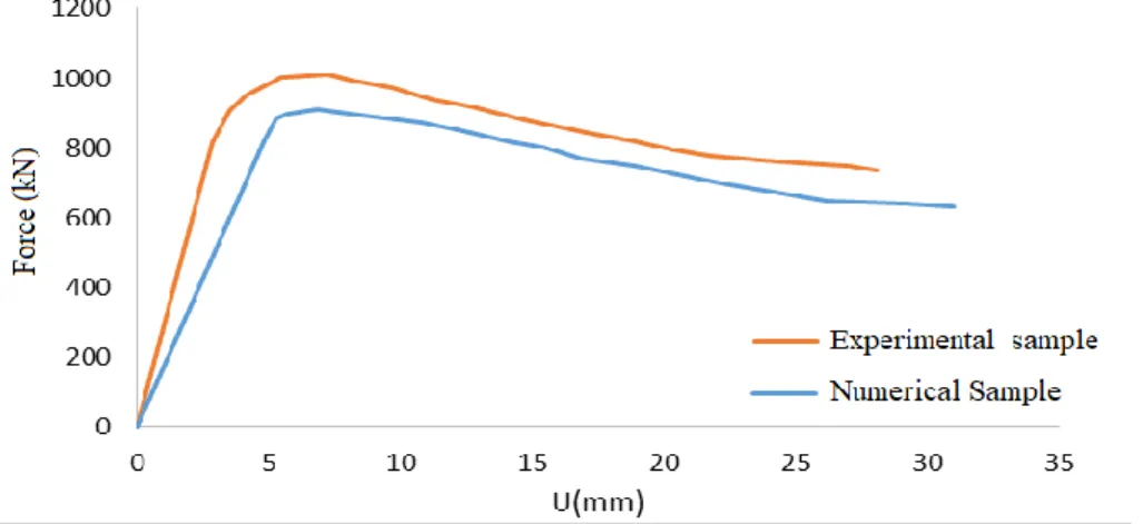
Figure 1. Cyclic loading Experimental studies of Qing-Xin et al. 2014 (Figure 2)
were used for numerical verification. Modeling the laboratory sample in the Abaqus software, and comparing force-shift-displacement diagrams, revealed that the
difference of force-displacement curves for the two samples was very small. That difference was about 5 percent. Figure 3 shows the force-displacement diagram.
Figure 2. Geometric shape of Qing-Xin Ren et al. [27]
Table 3. Mechanical Properties of Steel
Ultimate strain Stress yields
(Mpa) Elasticmodulus
(Mpa) Poisson's
ratio
0 370
200000 0.3
0.15 420
Concrete with a compressive strength of 46 MPa was defined by the model of Concrete Damage plasticity The boundary conditions of the specimens were applied under axial loading of 150,000 N. In the loading region, the specimen moves in the Y direction and is bounded in the X and Z transitional motion. (U2 0,
U
1
U
3
0
) And thesample can only rotate in the Z direction and is bound in the X and Y directions. The support in the X, Y and Z
directions is bound by transitional and rotational motion. The Solid C3D8R element was u sed to model the concrete core of the cft column, and the Shell element was used for modeling the steel tube section of the CFT column. For welded edges, the tie constraint was used, and the contact surface to surface was used to define the surface status of all the contacted plates (Table 3).
···
208
Figure 3. Validation Diagram
3. DISCUSS THE RESULTS OF THE ANALYSIS
After analyzing the study models in Visualization
graphical environment from the Abaqus program Different analytical parameters can be observed (Figure
4).
···
209 According to circular geometric cross-sectional studies, the A-1 specimen at 2 m height had no overall buckling due to the small slip coefficient, but local buckling occurred in the upper and lower back support. In specimen A-2 with column height 6 m with cross-section, the specimen did not have local buckling but had constant buckling in the middle part of the column due to the cyclic constant load compared to specimen A-1 with height 2 m, As the height of the column increases, the slenderness ratio increases and the column corresponding to it becomes more buckled earlier, causing the overall
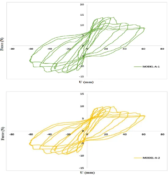
buckling to occur. The cross-section will be damaged and deteriorated at less load. After performing static nonlinear pushover analysis (NSP) under cyclic loading introduced for Group A case studies of the Abaqus Group A Curve Curve Graphics program that columns are 40 * 40 square geometric cross-sections 2 and 6 m, is plotted in Figure 5. After performing static nonlinear pushover, analysis (NSP) under cyclic loading introduced for group A case studies of the Abaqus program. The A-group Hysteresis curve, which is a column with a geometric cross-section of 40 * 40 and 2 and 6 m high, is shown in Figure 5.
Figure 5. Hysteresis diagram of group A samples under cyclic loading
By studying the diagrams in Figure 5, it was observed that the maximum cycle and load capacity in sample A-1 was 14.56 kN with a displacement value of 63 mm, and in sample A-2 the same load value calculated for a displacement of 63 mm. That is the equivalent of a load of 9.86 kN. This decrease in displacement was due to the
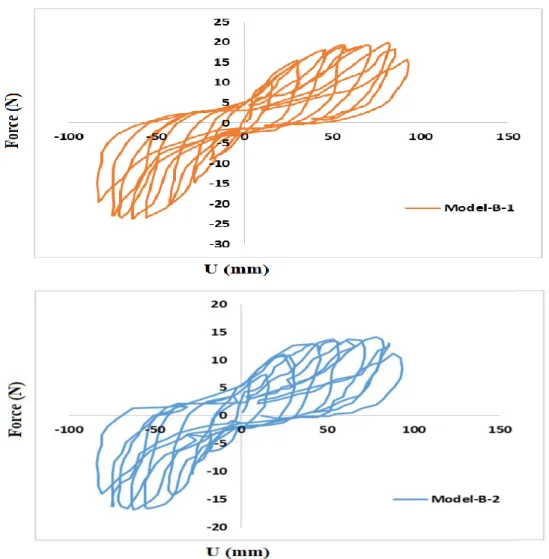
overall buckling occurring in the 6-m column, also after performing static nonlinear pushover analysis (NSP) under the cyclic loading introduced for group B case studies of the Abaqus Curve Graphic program. Group B, column with a circular geometrical cross-section 40 cm in diameter and 2 and 6 m high is plotted in Figure 6.
···
210
cyclic loading Hysteresis diagram of group B samples under
ure 6. Fig
In Group B samples, the highest cycles and load capacities arising from static overlay analysis for sample B-1 occurred at a height of 2 m at a load value of 20.63 kN at a displacement value of 75 mm, while the amount of charge at this displacement occurred. For example, the B-2 with a height of 6 m was 12.45 kN, the main reason for the reduction in load due to the overall buckling occurring at a height of 6 m, the main reason for this being the reduction in the load that the member wanted. It enters
its plastic range and does not utilize its plasticity capacity. After performing nonlinear static analysis of coatings in study group A with square geometry and A-1 model with 2 m height and A-2 model with 6 m height in Abaqus program environment under nonlinear static overlay analysis (NSP) In Figure 7, the Hysteresis curve diagram of two specimens A-1 and specimen A-2 from Study A is plotted in one figure.
···
211 From the Hysteresis diagram (11) obtained from nonlinear static overlay analysis (NSP), sample A-1 and sample A-2 are identified, which in sample A-1 is 2 m high with a square section of hysteresis sample due to The lower slip coefficient than the A-2 specimen at 6 m height shows a better performance of the structure, using this graph to show that the hardness value of the 6 m height section was 23.65% lower than the specimen hardness. With a height of 2 meters, also the formability of the 6-meter structure is 19.65 percent lower than the sample
size of 2 meters. After conducting nonlinear static analysis of study group B with square geometry and B-1 model with 2 m height and B-2 model with 6 m height in Abaqus program environment under nonlinear static analysis (NSP) in Figure 8. Hysteresis curve diagram of two specimens B-1 and specimen B-2 are plotted from study group B in a single, comparative form. Model B-1 performs better than Model B-2.
2 under cyclic loading
-1 and B
-of hysteresis diagrams -of model B Comparison
ure 8. Fig
From the hysteresis diagram of Figure 8, obtained from static nonlinear Push-up analysis (¬NSP), sample B-1 and sample B-2 are identified, with sample hysteresis in sample B-1 measuring 2 m in height. Because of the lower slip coefficient than the B-2 specimen with 6 m height, it
shows a better performance of the structure, using this graph it can be seen that the hardness value of the section with 6 m height is 21.34% less sample hardness. With a height of 2 meters, also the morphological value of the 6-meter structure is 18.74 percent lower than the sample size of 2 meters.
4. CONCLUSION
In this study, two groups of studies A and B were used to study the behavior of CFST columns with circular and square cross-sections, each of which had two subsets of studies with a total of four study samples named A-1. Abaqus 6.14 finite element software was used to model
the studied samples, A-2-B-2, B-1. The following results were obtained after modeling and performing static nonlinear Pushover (Nsp) analysis under cyclic loading:
- According to the comparison of hysteresis diagrams of A-1 and A-2 models, a 66.66% increase in height of A-2 compared to A-1 will decrease 27.14% of the resistance curve cross-section. , Which indicates that member slimming has led to poorer performance of CFST column behavior.
- Comparing the hysteresis diagram of the B-1 and B-2 models, it was observed that with a 66.66%
- increase in the height of the B-2 model compared to the B-1 model, the cross-section resistance
decreased by 24.65%. This indicates that the slender parameter in circular sections will be less affected by CFST composite columns than square sections.
- According to the comparison of hysteresis diagrams from static nonlinear overlay analysis of models A-1 and B-1, keeping height and geometrical deformation constant from square to circular sections increased 17.65% cross-section resistance curve This indicates that circular cross-sections in short CFST columns perform better than square columns in short columns.
···
212 - According to the comparison of the hysteresis
diagrams of models A-2 and model B-2, it was observed with a constant height and with the geometric deformation of the cross-section of
circles in model A-1 compared to model A-3. 17.65 percent of the hysteresis curve, which indicates that circular cross-sections in CFT columns perform better than tall square columns.
FUNDING/SUPPORT
Not mentioned any Funding/Support by authors.
ACKNOWLEDGMENT
Not mentioned by authors.
AUTHORS CONTRIBUTION
This work was carried out in collaboration among all authors.
CONFLICT OF INTEREST
The author (s) declared no potential conflicts of interests with respect to the authorship and/or publication of this paper.
5. REFERENCES
[1]Gardner L, Ashraf M. Structural design for non-linear metallic materials. Engineering Structures. 2006 May 1;28(6):926-34. [View at Google Scholar] ; [View at Publisher].
[2]Gardner NJ, Jacobson ER. Structural behavior of concrete filled steel tubes. ACI Structural Journal1967; 64(7):404-413. [View at Google Scholar] ; [View at Publisher].
[3]ACI Committee. Building code requirements for structural concrete (ACI 318-08) and commentary [Internet]. US: American Concrete Institute; 2007. Available from: https://books.google.com.ua/books.
[View at Google Scholar] ; [View at Publisher].
[4]Australia Standards. AS3600. Reinforced concrete structures. Sydney: Standards Australia; 1994. Available from: https://shop.standards.ie:443/en-au/country404/. [View at Google Scholar] ; [View at Publisher].
[5]Australia Standards. AS4100. Steel structures [Internet]. Sydney: Standards Australia; 1998. Available from: https://www.saiglobal.com /pdftemp/previews/osh/as/as4000/4100/n4100.pdf . [View at Google Scholar] ; [View at Publisher].
[6]EC4. Eurocode: Design of composite steel and concrete structures-part1-1: BS EN 1994-1-1, General rules and rules for buildings. London, UK: British standards Institution. 2004. [View at Google Scholar] ; [View at Publisher].
[7]AISC. Specification for structural steel buildings. American Institute for steel construction ANSI/AISC 360-05 [Internet]. Reston, chicago, Illinois, USA, 2005. [View at Publisher].
[8]Giakoumelis G, Lam D. Axial capacity of circular concrete-filled tube columns. Journal of Constructional Steel Research. 2004 Jul 1;60(7):1049-68. [View at Google Scholar] ; [View at Publisher].
[9]Guan M, Lai Z, Xiao Q, Du H, Zhang K. Bond behavior of concrete-filled steel tube columns using manufactured sand (MS-CFT). Engineering Structures. 2019 May 15;187:199-208. [View at Google Scholar] ; [View at Publisher].
[10]Naghipour M, Nemati M, Jalali J, Nematzadeh M. Effect of High Performance Concrete Mixture on Behavior of Passive and Active Confined CFT. International Journal of Theoretical and Applied Mechanics. 2018 Mar 14;3:17-25. [View at Google Scholar] ; [View at Publisher].
[11]Hwang JY, Kwak HG. FE analysis of circular CFT columns considering bond-slip effect: Evaluation of ultimate strength. Journal of
Constructional Steel Research. 2018 Jun 1;145:266-76. [View at Google Scholar] ; [View at Publisher].
[12]Murtuza, S., Kumar, N.S. Experimental Investigation on Circular Hollow Steel Columns in-Filled With Light Weight Concrete (With and Without GFRP) Under Cyclic Loading. International Journal of Research in Engineering and Technology. 2013 Nov; 9:116-124. [View at Google Scholar] ; [View at Publisher].
[13]Ghannam S. Buckling of Concrete-Filled steel tubular slender columns. International Journal of Research in Civil Engineering, Architecture & Design. 2015 Mar;3(1):41-7. [View at Google Scholar]
; [View at Publisher].
[14]Li YF, Chen SH, Chang KC, Liu KY. A constitutive model of concrete confined by steel reinforcements and steel jackets. Canadian Journal of Civil Engineering. 2005 Feb 1;32(1):279-88. [View at Google Scholar] ; [View at Publisher].
[15]Portolés JM, Romero ML, Bonet JL, Filippou FC. Experimental study of high strength concrete-filled circular tubular columns under eccentric loading. Journal of constructional steel research. 2011 Apr 1;67(4):623-33. [View at Google Scholar] ; [View at Publisher].
[16]O'Shea MD, Bridge RQ. Design of circular thin-walled concrete filled steel tubes. Journal of Structural Engineering. 2000 Nov;126(11):1295-303. [View at Google Scholar] ; [View at Publisher].
[17]Han LH. Tests on concrete filled steel tubular columns with high slenderness ratio. Advances in Structural Engineering. 2000 Oct;3(4):337-44. [View at Google Scholar] ; [View at Publisher].
[18]Sheikh SA, Uzumeri SM. Analytical model for concrete confinement in tied columns. Journal of the Structural Division. 1982 Dec;108(12):2703-22. [View at Google Scholar] ; [View at Publisher].
[19]Mander JB, Priestley MJ, Park R. Theoretical stress-strain model for confined concrete. Journal of structural engineering. 1988 Aug;114(8):1804-26. [View at Google Scholar] ; [View at Publisher].
[20]Chen CC, Lin NJ. Analytical model for predicting axial capacity and behavior of concrete encased steel composite stub columns. Journal of Constructional Steel Research. 2006 May 1;62(5):424-33. [View at Google Scholar] ; [View at Publisher].
[21]Mirza SA, Skrabek BW. Statistical analysis of slender composite beam-column strength. Journal of Structural Engineering. 1992 May;118(5):1312-32. [View at Google Scholar] ; [View at Publisher].
···
213
[22]Pazant , PP. Cedolin, L. Stability of Structures. Elastic, Inelastic, Fracture and Damage Theories[Internet]. Courier Dover Publications; 2010.Available from: https://books.google.com/books?hl=en&lr=&id =CmnBPcLy2A4C&oi=fnd&pg=PR7&dq. [View at Google Scholar] ;
[View at Publisher].
[23]Mursi M, Uy B. Strength of concrete filled steel box columns incorporating interaction buckling. Journal of Structural Engineering. 2003 May;129(5):626-39. [View at Google Scholar] ; [View at Publisher].
[24]Ellobody E, Young B. Numerical simulation of concrete encased steel composite columns. Journal of Constructional Steel Research. 2011 Feb 1;67(2):211-22. [View at Google Scholar] ; [View at Publisher].
[25]Farajpourbonab E, Kute SY, Inamdar VM. Steel-reinforced concrete-filled steel tubular columns under axial and lateral cyclic loading. International Journal of Advanced Structural Engineering. 2018 Mar 1;10(1):61-72. [View at Google Scholar] ; [View at Publisher].
[26]Kwon YB, Seo SJ, Kang DW. Prediction of the squash loads of concrete-filled tubular section columns with local buckling. Thin-walled structures. 2011 Jan 1;49(1):85-93. [View at Google Scholar] ; [View at Publisher].
[27]Ren QX, Han LH, Lam D, Hou C. Experiments on special-shaped CFST stub columns under axial compression. Journal of Constructional Steel Research. 2014 Jul 1;98:123-33.[View at Google Scholar]; [View at Publisher].