Sharif University of Technology
Scientia IranicaTransactions B: Mechanical Engineering www.scientiairanica.com
Numerical study of the eects of process parameters on
tool life in a cold radial forging process
H. Afrasiab
aand M.R. Movahhedy
b;a. Department of Mechanical Engineering, Babol University of Technology, Babol, Iran. b. School of Mechanical Engineering, Sharif University of Technology, Tehran, Iran. Received 15 January 2012; received in revised form 8 July 2013; accepted 4 November 2013
KEYWORDS Radial forging; Finite element; Tool life; Wear;
Mechanical fatigue.
Abstract. Radial forging is an open die forging process used for reducing the diameters of shafts, tubes, stepped shafts and axles, and for creating internal proles in tubes. Due to very large forging loads, the tool should withstand high stress and wear. Therefore, the success of the forging process depends upon recognition of the die failure factors and optimization of the tool working conditions that enhance tool life. In this study, the eect of process parameters on tool life in the cold radial forging process is investigated using nonlinear three dimensional nite element modeling. Wear and mechanical fatigue are considered as the main modes of tool failure, and a parametric study on the eect of process parameters on tool life is presented.
© 2014 Sharif University of Technology. All rights reserved.
1. Introduction
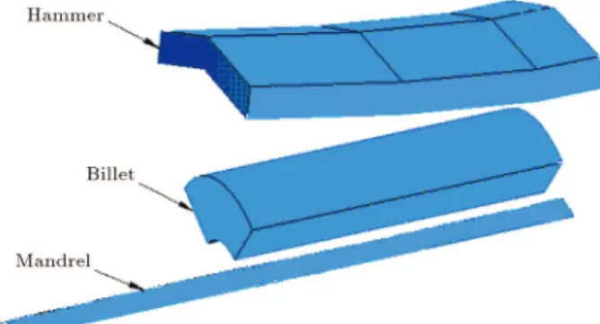
Radial forging is a hot or cold forging process in which two or four hammers (dies) with radial strokes are utilized for forging solid or tubular components. This process is usually used for reducing the diameter of ingots and bars, the forging of stepped shafts and axles, and the production of tubular components with and without internal proles, such as rie barrels [1]. Deformation in radial forging results from a large number of short cycle, high speed hammer impacts on the workpiece. The workpiece has both rotational and axial feed between the strokes, and dies are arranged circumferentially around the workpiece, as shown in Figure 1 [2,3].
The Radial Forging (RF) process has been investi-gated by many researchers in the past. Lahoti et al. [4] and Lahoti and Altan [2] analyzed the mechanics of RF for single and compound angle dies using a slab
*. Corresponding author. Tel.: +98 21 66165505; Fax: +98 21 66000021
E-mail address: [email protected] (M.R. Movahhedy)
method. In another study, Lahoti et al. [5] studied the eects of die design parameters on deformation in the RF. Using a modular upper bound technique, Subramanian et al. [6] modeled metal ow in a die cavity during the riing of gun barrels under plane strain condition. Ghaei et al. [3] studied the eects of die shape in RF using slab method analysis. In another work, they used an upper bound method to estimate the maximum required forging load in RF [7]. In more recent work, the nite element method has been used to model and predict the RF process. Tszeng and Kobayashi [8] were the rst to model the process of tube forging using the FEM. Domblesky et al. [9] presented a nite element model to determine the strain, strain rate, and temperature distribution in radial forging. Jang and Liou [10] also used FEM to evaluate the residual stresses in RF. Ghaei and Movahhedy [11] used a full 3D FEM simulation to model the radial forging process and investigated the eects of die cross-section on tube deformation. In another study, they [3] used FEM to study the radial forging of tubes without a mandrel and compared the predicted forging load with available experimental data.
Figure 1. Arrangement of radial forging dies.
The forging loads are usually very high. The die should withstand high stress and tool life is a deter-mining factor. Therefore, it is essential to recognize the failure modes and to optimize the working conditions of the tool to enhance tool life and achieve high productivity. The failure of a tool slows production, increases rejected parts, and requires new adjustment to the machine. Often, in practice, the lifetime of the tool is not optimized, which means a loss of around 10% of the cost of the nished part [12]. Excessive die wear and cracks due to fatigue are common modes of die failure in radial forging applications. According to an investigation about die life, as much as 70% of the tools have to be replaced because of wear. Another 25% are due to mechanical fatigue, and the remaining 5% are due to plastic deformation and thermal-mechanical fatigue [13,14].
Tool life and tool failure in various cold, warm and hot forging processes have been extensively studied in the literature [12,13,15-19]. This study focuses on tool life in the radial forging process and is aimed at investigation of the eects of various process param-eters on die life in this process. A nonlinear three dimensional nite element model of radial forging is developed. The die is modeled as deformable bodies, and a stress based criterion for tool failure is presented. The dissipated energy and the maximum Von-Mises stress in the die are used for the prediction of wear and mechanical fatigue, respectively. The eects of die geometrical features and process parameters, such as feed rates and frictional conditions, on tool failure are investigated.
2. Modeling procedure
A three dimensional model is developed for sim-ulation of the radial forging of tubes using the ABAQUS/Standard commercial FE code. First order brick elements with reduced integration and hourglass control are used to mesh the tube. Since the die and the mandrel undergo very little deection compared to the deforming tube, it is common to model them as rigid bodies [3,11]. However, to study die life, the stresses developed in the die are needed, and, therefore,
in the current study, the die is modeled as a deformable body. The mandrel is modeled using 3D rigid 4-node elements. Due to the symmetry of the process geometry, it is sucient to model only one eighth of a mandrel and half of a hammer (die) to reduce computational time.
It is assumed that the process is performed under isothermal conditions. The simulated tube is made of AISI 1015. A power law constitutive law, in the form of = k"n, is used [1], where k and n values at
room temperature are given as k = 618:14MPa and n = 0:1184. The die material is cold worked tool steel material (AISI D2) with an initial yield stress of 1600 MPa. The elastic modulus and Poisson ratio for both tube and die materials are 210 MPa and 0.3, respectively. The frictional contact between contacting surfaces is implemented using a penalty method. In order to obtain the limiting shear stress, a check-run analysis was performed initially, assuming frictionless contact surfaces, and the maximum Von-Mises was found to be around 420 MPa in the workpiece. The lim-iting shear stress was set equal to =p3 = 420=p3 = 240 MPa in subsequent analyses. Also, the Coulomb friction coecient was set to be 0.2. Figure 2 shows the conguration of the die, tube and mandrel in the simulation.
A schematic view of a typical radial forging die is shown in Figure 3. The most important features to inuence process outcome are the conical inlet, the cylindrical section and the transverse angle.
A longitudinal section of the radial forging die
Figure 2. Conguration of the die, tube and mandrel.
is shown in Figure 4. The inlet angle, which is the angle of the conical inlet () and the land length of the cylindrical part (b), are shown in this gure. The transverse section of the die is shown in Figure 5, on which the transverse angle () is demonstrated.
The tube, die and mandrel geometries are de-scribed in Tables 1 to 3, respectively. Note that some of the die parameters are simulated with a range of values to study their eect on the process parameters.
Figure 4. Longitudinal section of die, showing inlet angle () and land length (b).
Figure 5. Transverse section of die, showing transverse angle ().
Table 1. Initial and nal tube geometry. Outer radius of preform O.D. 15.5 mm Inner radius of preform I.D. 5.8 mm Length of the preform L0 312 mm Outer radius of forged product o.d. 12 mm Inner radius of forged product i.d. 3.915 mm Length of the forged product Lf 490 mm Percentage of reduction in area Red 38%
Table 2. Die geometry. Die inlet angle 4 to 10 Die transverse angle 135 to 165 Die land length LLAND 2 to 20 mm Length of die inlet LI 21 mm Total length of die LDIE 70 mm Total depth of die HDIE 37 mm
Table 3. Mandrel geometry. Radius of mandrel RM 3.915 Eective length of mandrel LM 40 mm Angle of tapered head 15 Length of tapered head LT:H 3.7 mm
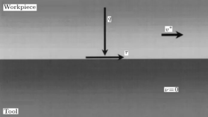
Figure 6. Diagram showing the conditions on the tool/workpiece interface [13].
3. Wear analysis
Wear is the progressive loss of material from the operating surface of a body caused by relative motion at its interface with another surface [20,21]. Many models have been developed for estimation of the wear amount at contacting interfaces. Most wear models correlate wear volume with physical quantities, such as load, sliding distance, coecient of friction, and hardness, etc. The wear criterion used in this paper is the dissipated energy model, which assumes that the amount of wear is dependent on the dissipated energy at the tool/workpiece interface. According to this model, the worn-o material, V , is proportional to the dissipated energy per area, w, when the material slides a distance, l, along a tool surface under the inuence of shear stress, , as shown in Figure 6 [13,14,20,21]. This function is given as:
V = k w = k l: (1)
The coecient, k, is called the specic wear rate, and is calculated from the following equation:
k = KH; (2)
in which H is the ratio between the hardness of the workpiece and the tool, and the wear coecient, K, is the coecient of proportionality used as a measure of the material wear behavior.
The contact shear stress and the sliding length at the die/workpiece interface are obtained for all interface nodes from the FE simulation. In addition, the maximum Von-Mises stress on the die/workpiece interface is used as the measure of die stress in each case.
4. The eects of die geometry and process parameters on die life
The eects of die geometrical features and workpiece rotational feed rate on tool failure are investigated separately in the following paragraphs.
4.1. Die inlet angle
Figure 7 shows the sliding length at the die/workpiece interface and the shear stress on this surface under dierent die inlet angles. The axial feed and other parameters are kept constant for all cases. The gure shows that when this angle increases, the shear stress, mainly due to friction, does not vary signicantly. However, the sliding length decreases with an increase in inlet angle. As the die inlet angle increases, the area of the contact surface between the die and the workpiece decreases, and the workpiece material travels a smaller distance on the die surface, which reduces the sliding length. This leads to a decrease in wear for larger die inlet angle, as shown in Figure 8.
Figure 9 shows the forging force and maximum
Figure 7. Shear stress and sliding length on the die/workpiece interface.
Figure 8. Eect of die inlet angle on the die wear.
Figure 9. Eect of die inlet angle on the force and stress created in the die.
Von-Mises stress on the die for dierent die inlet angles. As the die inlet angle increases, a smaller portion of the workpiece is deformed in each die stroke, which leads to the reduction of the force and Von-Mises stress, as shown in Figure 9. This is consistent with the prediction of less wear at higher inlet angles.
It is, thus, observed that increasing die inlet angle decreases both wear and maximum stress in the die. Consequently, a larger die inlet angle is preferred for increasing die life in the radial forging process. It should be noted, however, that a larger die inlet angle reduces penetration of the plastic deformation in the depth of the workpiece, and lowers the uniformity of deformation in the forged product.
Further examination of simulation results shows that maximum stress occurs at the middle of the die conical inlet, where the die/workpiece contact begins and deformation is maximum, as well as at the end of the die cone near the cylindrical part, where the work hardened material is deforming. Sample contour plots of the Von-Mises stress on the die inner and outer surfaces are shown in Figures 10 and 11.
Figures 12 and 13 show the contour plots of the contact shear stress and the contact sliding length at the interface, respectively. It is observed that the maximum values of both parameters occur at parts of the workpiece that are in contact with the end of the die cone near the cylindrical part. Therefore, the
Figure 10. Contour plot of the Von-Mises stress on the die inner surface.
Figure 11. Contour plot of the Von-Mises stress on the die outer surface.
Figure 12. Contour plot of the contact shear stress on the workpiece outer surface.
Figure 13. Contour plot of the contact sliding length on the workpiece outer surface.
Figure 14. Shear stress and sliding length on the die/workpiece interface.
energy per area, which is the measure of die wear, is maximum there. These regions of die are also where the Von Mises stress is maximum.
4.2. Die transverse angle
Figure 14 shows the sliding length at the die/workpiece interface and the shear stress on this surface for dierent die transverse angles. Similar to the eects of inlet angle, the increasing of the transverse angle does not aect shear stress signicantly, but the sliding length decreases. This is due to the fact that for smaller transverse angles, forging dies better encircle the work-piece and apply more plastic deformation on it. Thus, the ow of the workpiece material on the die surface increases and the sliding length increases, as shown in Figure 14. This matter, as shown in Figure 15, leads to increase of wear at smaller transverse angles.
Figure 15. Eect of die transverse angle on the die wear.
Figure 16. Eect of the die transverse angle on the forging force and stress created in the die.
The increased plastic deformation at smaller angle also raises the forging force, as shown in Figure 16. However, the results show that the smallest value of maximum Von-Mises stress in the die occurs at a transverse angle of 155 degrees. In the radial forging of circular rods, the workpiece contacts each die surface at two points. As the transverse angle increases, these points approach each other on the die surface, such that, at the transverse angle of 180 degrees, there will be just one contacting point. But, the approaching of the contacting points reduces the spread of stress in the die and concentrates it into a smaller region, leading to an increase of stress in that region. Therefore, by increasing the die transverse angle, the applied force and concentration of stress on the die decrease. It seems that the presence of this dual eect causes the smallest maximum Von-Mises stress of the die at the transverse angle of 155 degrees.
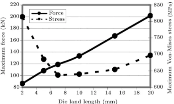
4.3. Die land length
Figure 17 shows the shear stress and sliding length on the die/workpiece interface for dierent die land lengths. At increased land lengths, the frictional shear stress remains almost constant, but the contacting surface between the die and the workpiece is enlarged, leading to an increased sliding length and, thus, wear volume, as shown in Figure 18.
Figure 17. Shear stress and sliding length on the die/workpiece interface.
Figure 18. Eect of die land length on the die wear.
Figure 19. Eect of the die transverse angle on the force and stress created in the die.
Figure 19 shows the force and maximum Von-Mises stress created in the die for dierent die land lengths. As the land length increases, a bigger portion of workpiece is deformed at every stroke and the forging force increases. This rise in the forging force leads to the increase of stress at larger land lengths. According to Figure 19, this is the case except for very small amounts of land length. It is likely that an excessive decrease of land length leads to a mechanical weakening of the die land and the rising of Von-Mises stress in this region. The land length that seems the best for optimal die life in the studied process is around 7 mm.
Figure 20. Shear stress and sliding length on the die/workpiece interface.
Figure 21. Eect of the workpiece rotational feed rate on the die wear.
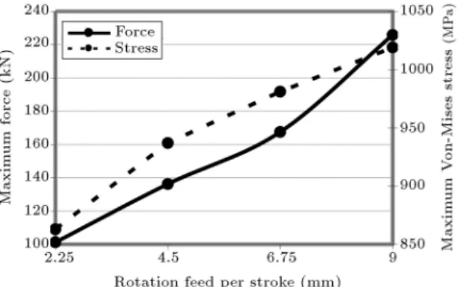
4.4. Workpiece rotational feed rate
Besides axial feed, the workpiece is also rotationally fed between strokes. Figure 20 presents the eect of the workpiece rotational feed per stroke on the interfacial shear stress and sliding length. It can be seen that the frictional shear stress at the die/workpiece interface is nearly constant for dierent values of the workpiece rotational feed, but the sliding length increases. In each die blow, points of the workpiece that are in contact with the die are radially forced towards the workpiece center, while points of the workpiece that lie between the two neighboring dies move further from the center. When the workpiece is rotationally fed between the strokes, these latter points come into contact with the die. At an increase in rotational feed, larger parts of the escaping materials of the last blow are contacted and forced to deform in the current blow. This increases plastic deformation and the workpiece material ow on the die surface in each blow. So, the interfacial sliding length increases, which leads to a rise in die wear volume, as shown in Figure 21.
The increased amount of plastic deformation in each blow also increases the forging force and the max-imum Von-Mises stress is created in the die, according to Figure 22. So, similar to axial feed rate, smaller
Figure 22. Eect of the workpiece rotational feed rate on the force and stress in the die.
rotational feed results in larger tool life, but reduced production rate.
5. Conclusion
In this study, a nonlinear three dimensional Finite Element Method (FEM) was used for the modeling of a cold radial forging process. The objective was to investigate the eect of die geometry and process parameters on the die life. To this end, wear volume and mechanical fatigue were investigated. Among the parameters considered, the increase of die inlet angle improves die life, while an increase in rotational feed rate has detrimental eects on die life. Furthermore, parameters, such as the die transverse angle and the die land length, have optimum values that represent the largest service life of the die.
References
1. Altan, T., Oh, S.I. and Gegel, H., Metal Forming Fundamentals and Applications, American Society for Metals, Materials Park, 20(3), pp. 114-115 (1983).
2. Lahoti, G.D. and Altan, T. \Analysis of the radial forging process for manufacturing of rods and tubes", J. of Eng. for Ind., 98(1), pp. 265-271 (1976).
3. Ghaei, A., Movahheddy, M.R. and Taheri, A.K. \Study of the eects of die geometry on deformation in the radial forging process", Journal of Material Processing Technology, 170(1-2), pp. 156-163 (2005).
4. Lahoti, G.D., Dembowski, P.V. and Altan, T. \Radial forging of tubes and rods with compound-angle dies", Proceeding of NAMRC-IV, 1, Columbus, USA, pp. 87-98 (1976).
5. Lahoti, G.D., Liuzzi, L. and Altan, T. \Design of dies for radial forging of rods and tubes", J. Mech. Working Technol., 1(1), pp. 99-113 (1977).
6. Subramanian, T.L., Venkateshwar, R., Lahoti, G.D. and Lee, F.M. \Experimental and computer modeling of die cavity ll in radial forging of riing", Proceeding of Process Modeling Sessions, Process Modeling Funda-mentals and Applications to Metals, 1, USA, pp. 341-346 (1979).
7. Ghaei, A., Taheri, A.K. and Movahhedy, M.R. \A new upper bound solution for analysis of the radial forging process", Int. J. Mech. Sci., 48(11), pp. 1264-1272 (2006).
8. Tszeng, T.C. and Kobayashi, S. \Determination of residual stresses in radial forging", Manufacturing Processes Simulation, 20(1), pp. 31-45 (1986).
9. Domblesky, J.P., Shivpuri, R. and Painter, B. \Appli-cation of nite-element method to the radial forging of large diameter tubes", Journal of Material Processing Technology, 49(1), pp. 57-74 (1995).
10. Jang, D.Y. and Liou, J.H. \Study of stress develop-ment in axi-symmetric products processed by radial forging using a 3-D nite-element method", Journal of Material Processing Technology, 74(1), pp. 74-82 (1998).
11. Ghaei, A. and Movahhedy, M.R. \Die design for the radial forging process using 3D FEM", Journal of Material Processing Technology, 182(1-3), pp. 534-539 (2007).
12. Dubar, M., Dubois, A. and Dubar, L. \Wear analysis of tools in cold forging: PVD versus CVD TiN coatings", Wear, 259(7-12), pp. 1109-1116 (2005).
13. Stahlberg, U. and Halstrom, J. \A comparison between two wear models", Journal of Materials Processing Technology, 87(1-3), pp. 223-229 (1999).
14. Lee, R.S., and Jou, J.L. \Application of numerical simulation for wear analysis of warm forging die", Journal of Materials Processing Technology, 140(1-3), pp. 43-48 (2003).
15. Vazquez, V., Hannan, D. and Altan, T. \Tool life in cold forging - an example of design improvement to increase service life", Journal of Materials Processing Technology, 98(1), pp. 90-96 (2000).
16. Turk, R., Perus, I. and Tercelj, M. \New starting points for the prediction of tool wear in hot forging", International Journal of Machine Tools & Manufac-ture, 44(12,13), pp. 1319-1331 (2004).
17. Brucelle, O. and Bernhart, G. \Methodology for ser-vice life increase of hot forging tools", Journal of Materials Processing Technology, 87(1-3), pp. 237-246 (1999).
18. Hansen, P.S., Bayb, N., Gronbaek, J. and Brondsted, P. \Fatigue in cold-forging dies: Tool life analysis", Journal of Materials Processing Technology, 95(1-3), pp. 40-48 (1999).
19. Barrau, O., Boher, C., Gras, R. and Rezai-Aria, F. \Analysis of the friction and wear behaviour of hot work tool steel for forging", Wear, 255(7-12), pp. 1444-1454 (2003).
20. Ramalho, A. and Miranda, J.C. \The relationship be-tween wear and dissipated energy in sliding systems", Wear, 260(4-5), pp. 361-367 (2006).
21. Huq, M.Z. and Celis, J.P. \Expressing wear rate in sliding contacts based on dissipated energy", Wear, 252(5-6), pp. 375-383 (2002).
Biographies
Hamed Afrasiab received his B.S., M.S. and Ph.D. degrees all in Mechanical Engineering from Sharif University of Technology, Iran, in 2004, 2006 and 2011, respectively. He is currently a Professor at the Department of Mechanical Engineering, Babol University of Technology, Iran. His main research interests are nite element simulation of the solid, uid and uid-structure interaction problems, stress-strain analysis, and modeling of metal forming pro-cesses.
Mohammad Reza Movahhedy received his B.S. degree from University of Tehran, Iran, in 1988, his M.S. degree from University of Waterloo, Canada, in 1994, and his Ph.D. degree from the University of British Columbia, Canada, in 2000, all in Mechanical Engineering. He is currently a Professor at the De-partment of Mechanical Engineering, Sharif University of Technology, Iran. His research interests are FEM simulation of metal cutting/forming processes, machine tools dynamics, mechanics of machining processes, experimental modal analysis, and computer aided tol-erancing.