Evaluation of the Vertical Distribution of
Base Shear Force in Base-Isolated Structures
F.R. Rofooei
and M. Ebrahimi
1Application of the base-isolation systems, as a means to limit the seismic-induced response of structures, has attracted the attention of many engineers and researchers. Due to their importance, the Uniform Building Code (UBC) has incorporated a special section for the seismic analysis and design of base-isolated structures since its 1991 edition. The present work investigates the vertical distribution of the lateral seismic force for base-isolated structures provided by the 1997 edition of UBC (UBC97). Dierent 6 and 8-story, 3-D base-isolated structural models with LRB isolators are considered, having a variety of eective periods and eective damping ratios. The UBC97 analysis procedure for the base-isolated structures is used to determine the minimum lateral seismic force and its vertical distribution for dierent oors. Since the number of stories above the isolation interface is more than four for the considered isolated structural models, the response spectrum analysis is used, considering the equivalent linear properties for isolation systems. Also, the UBC97 recommended that the 5%-damped design spectra be properly modied to account for the actual modal damping ratios of an isolated structure. Extensive nonlinear dynamic analyses were performed for 8 types of LRB isolators, using appropriately normalized earthquake accelerograms recorded onS
A and S
B soil proles. Both the superstructure and the isolators are allowed to behave nonlinearly, in order to evaluate the seismic induced demand shear force on dierent oors. The peak base center and corner displacements, maximum base and story shear forces and the maximum inter-story drifts are determined for dierent base-isolation systems and earthquake records. The results, together with their mean and mean plus one standard deviation values, are used for the evaluation of UBC97 response spectrum analysis procedures for these buildings. The results indicate that the UBC97 suitably predicts the seismic lateral forces for base-isolated buildings. However, it does not provide a good estimate of the shear force distribution over the height, especially for the highly damped base-isolation systems. Furthermore, the number of columns per story that behaved nonlinearly during the time history analyses is included for comparison.
INTRODUCTION
Passive control mechanisms, including dierent base-isolation systems, are gaining much attention as a means to protect structures against seismic hazards. Seismic isolation, for controlling the response of struc-tures, is a relatively old concept, to mitigate the damage potential due to earthquakes. It is an approach to earthquake-resistant design that is primarily based
*. Corresponding Author, Department of Civil Engineering, Sharif University of Technology, Tehran, I.R. Iran.
1. Department of Civil Engineering, Sharif University of Technology, Tehran, I.R. Iran.
on reducing the seismic demand, rather than increasing the resistance capacity of the systems. The advantage of this concept lies in its ability to provide a discon-tinuity between the structure and the foundation that partially decouples ground motion from the structure, causing a lower level of response than would have been obtained otherwise. Analytical and experimental results have shown the eectiveness of dierent base-isolation systems in reducing the seismic-induced forces exerted on structures [1,2].
Some types of isolation system, such as Lami-nated Rubber Bearings (LRB), improve the seismic performance of structures by introducing exibility to the system. Assuming a sti soil prole for the
site, the exibility of the isolation system shifts the fundamental period of the isolated structure to a period larger than the predominant periods of strong ground motion. It will result in lower accelerations and elastic forces for the superstructure. Therefore, one can expect base-isolated structures to be designed for smaller seismic lateral forces in comparison to similar xed based buildings. That, in turn, reveals the need for a relevant design code for these types of building structure.
In that regard, in 1986, the Structural Engineers Association of Northern California (SEAONC) pub-lished its rst recommended design guideline for seis-mically isolated buildings [3]. This was followed by the development of \tentative general requirements for the design and construction of seismic isolated structures" that was prepared by the seismology committee of SEAOC as an appendix to \SEAOC recommended lat-eral force requirements" in 1990 [4]. The International Conference of Building Ocials (ICBO) adopted the requirements and included them in the 1991 Uniform Building Code (UBC), which were further revised in their subsequent revisions in 1994 and 1997 [5-7]. Also, since June 1991, the American Association of State Highway and Transportation Ocials (AASHTO) in-corporated similar provisions for design of bridge seis-mic isolation systems in their Guide Specications for Seismic Isolation Design [8]. The intent of these provi-sions is to control structural damage by restricting any possible large lateral displacements and/or nonlinear behavior to the isolation system only. That would leave the superstructure with a dominant rigid body motion on the isolator's interface without any considerable whiplash eect during large earthquake events.
Since the introduction of the newly proposed seismic analysis provisions for base-isolated structures, various investigations have been carried out to eval-uate the proposed guidelines. In an intensive study, Kircher and Lashkari investigated the validity of the SEAONC86 static analysis procedure [9]. They con-sidered a rigid superstructure located on a grid of 45 isolators with 13 dierent bilinear hysteretic behaviors. The isolation system properties covered an entire range of interest in seismic isolation i.e., eective periods of 1 to 4 seconds and eective damping ratios from 6% to 39% of critical damping. The parametric study was carried out using a comprehensive collection of 29 pairs of properly scaled horizontal earthquake accelerograms. In general, the study conrmed that the recommended displacement by the static analysis procedure for isolation systems is reasonable. This study ignored superstructure exibility, bi-directional interaction in the base-isolation systems and the fact that the bilinear hysteretic models did not strictly apply to frictional systems, since they all had a yield displacement of 0.5 inches. The eect of bi-directional
interaction in the isolators for hysteretic softening systems was investigated by Mokha (1993) [10]. It was concluded that neglecting the bi-directional eect can lead to underestimation of the isolation system's displacement.
In a following study by Constantinou et al. (1991) on sliding isolation systems, the same conclusions were drawn [11]. In their study, the superstruc-ture was assumed to be exible, taking into account the bi-directional interaction eect of the isolation's bearings. Subsequently, Winters and Constantinou, compared the results of the response spectrum and the SEAOC/UBC static analysis limits for the bearings' displacements and the shear force distribution over the height, with those obtained from nonlinear time history analyses [12]. The same earthquake records and isolation systems as in Kircher and Lashkari were con-sidered for the nonlinear time history analyses to nd the best estimate of the real response of base-isolated structures. Also, to evaluate the seismic performance of base-isolation systems, Lin and Shenton studied the seismic behavior of xed-base and base-isolated concentrically braced and special moment resisting steel frames [13]. They designed the xed-base frames in accordance with SEAOC recommended lateral force, while the base-isolated frames were designed to 100%, 50% and 25% of the SEAOC recommended lateral force level. Nonlinear time-history dynamic analyses were conducted using 54 strong ground motion records. The number of yielded elements and total and relative roof and isolation-bearing displacements were statistically evaluated. They concluded that a comparable or better performance for the base-isolated braced frames, designed to 50% of the SEAOC recommended lateral force, can be expected. Also, comparable performance was achieved for base-isolated moment resisting frames at various design force levels, depending on the perfor-mance criteria.
The present study investigates the validity of the shear force distribution proposed by UBC97 for base-isolated structures. First, several 6-story superstruc-tures are considered that have been isolated by eight dierent isolation systems with various eective periods and damping ratios. It is followed by considering a few 8-story superstructures isolated by highly-damped isolation systems, for which the UBC97 proposed ver-tical shear force distribution was found to be severely underestimated. Also, both the superstructure and the isolators are allowed to behave nonlinearly, in order to evaluate the seismic induced demand shear force on dierent oors. In the following, rst, the static lateral force method of UBC97 and necessary details about the structural models are briey presented. The numerical results are evaluated and the eciency of the current UBC code, in estimating seismic demand for base-isolated structures, is investigated.
THEUBC STATIC LATERAL RESPONSE METHOD
In UBC97, the following displacements for the center of rigidity of isolation systems are dened at the Design Basis Earthquake (DBE) and the Maximum Credible Earthquake (MCE) levels, respectively:
D D= g 4 2 C VD T D B D ; D M = g 4 2 C VM T M B M ; (1)
in which D D and
D
M are the design and maximum displacements, respectively, C
VM and C
VD are the seismic coecients,T
Dand T
M are the eective periods of the seismic isolated structure at the design and maximum displacements, respectively, andB
Dand B
M are the numerical eective damping coecients, which are related to the eective damping of the isolation system at the design and maximum displacements, respectively. Eective periods, T
D and T
M, are also dened as:
T D= 2
s W K Dmin g ; T
M = 2 s W K Mmin g ; (2) where K
Dmin and K
Mmin are the minimum eective stiness of the isolation system at the design and maximum displacements in each of the horizontal directions under consideration, respectively. According to UBC97, the structure above the isolation system shall be designed to withstand a minimum shear force, V
s, equal to: V s= K Dmax D D R I : (3)
In the above equation,K
Dmaxis the maximum eective stiness of the isolation system at the design displace-ment and R
I is the force reduction factor, based on the type of structural system. The value ofR
I for the moment-resisting frame system is 2.0, as per UBC97 code. The total base shear force shall be distributed over the height of the structure above the isolation interface, in accordance to the following formula:
F x= V s w x h x n P i=1 w i h i ; (4)
in which w x and
w
i represent the total seismic dead load assigned to leveli orx, respectively, and h
i and h
xare the elevations of levels
iorx, with respect to the isolation interface. Also, for xed-base structures, the total design base shear, according to UBC97 guidelines, shall be determined from:
V = C a I R T W; (5) where, C
a is the seismic coecient related to the soil prole type and the seismic zone factor Z, I is the importance factor, R is the reduction factor, which is equal to 8.5 for the special moment-resisting steel frame and 4.5 for ordinary moment-resisting steel frame and T is the fundamental period of the structure that is given by:
T =C t(
h n)
3=4
; (6)
whereC t= 0
:0853 for the steel moment-resisting frame andh
nis the height of the building in meters. Finally, the total base shear is distributed over the height of the building, according to:
F x= (
V F t) w x h x n P i=1 w i h i ; (7)
in which,F t= 0
:07TV <0:25V.
STRUCTURAL MODELSANDISOLATION
SYSTEMS
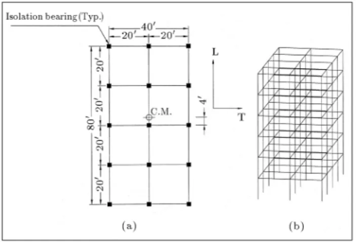
The superstructure models considered in this study consist of 6 and 8-story moment resisting frames. In plan, the 6-story structures are congured to be rectangular, two bays by four bays, each bay measuring 20 feet. The height of each story is equal to 12 feet. All the structural elements have the same stiness in transversal and longitudinal directions. In the design process, the same column sections were used for every two stories. The weight of each oor and the base is 320 kips, leading to a total weight of 2240 kips for the superstructure. In order to create an eccentricity of 5% of the longest dimension of each oor, the mass of each oor was selected to be asymmetric. A schematic 3-D and plan view of the superstructure is shown in Figure 1.
The 8-story superstructure models were also mo-ment resisting frames and, in plan, they consisted of four bays by eight bays, with each bay measuring 20 feet. The height of each story is the same as the 6-story models. Similar to the previous case, the column sections are changed every two stories. The weight of each oor and the base is considered to be 1280 kips, with a total weight equal to 11520 kips for the superstructure. Like the previous case, the oor mass centers were appropriately dislocated to create an eccentricity of 5% of the longest dimension. Figure 2 shows the plan view of the 8-story superstructure and the location of its isolators. All non-linear analyses have been performed by ANSYS5.4 [14]. The super-structure elements have been modeled using BEAM24, a 3-D thin-walled plastic beam element, and isolators have been modeled using COMBIN39, a non-linear spring element with tension-compression, 3-D torsion and large deformation capabilities.
Figure 1.
a) Plan view of the 6-story isolated structural model with the location of the isolation bearings and the mass center; b) A schematic 3-D view of the structural model.Figure 2.
Plan view of the 8-story building models and location of the base-isolation bearings.ISOLATION SYSTEMS
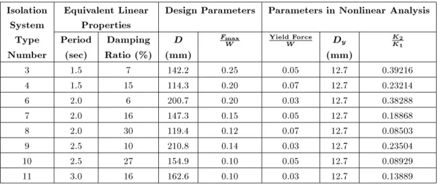
The isolation systems used in this study are identical to those used by Kircher and Lashkari (1989) and are applicable to rock and sti soil sites [9]. Since the UBC97 regulations do not allow the application of iso-lation systems with eective damping ratios exceeding 30%, those isolations systems were excluded from this study. The force-displacement characteristics of the isolation systems were modeled by bi-linear behavior, as shown in Figures 3 and 4. Table 1 summarizes the properties of the isolation systems analyzed on sti soil sites. The behavior of superstructure elements has also been considered as bi-linear. The slope of the rst portion on the stress-strain diagram is taken as that of normal ASTM A36 rolled steel up to the point of F
y = 2400 kg/cm
2. The strain hardening portion has
been assumed to have a slope equal to 10% of that of the rst portion. Using the aforementioned isolators,
Figure 3.
Idealized properties of the base-isolation system.Figure 4.
Force-displacement properties of isolation systems analyzed on sti soil sites.a set of eight 6-story isolated structures, marked by numbers 3, 4 and 6 to 11, are designed, as shown in Table 2. Also, the 8-story base-isolated models, with highly damped isolation systems (isolators type 8 and 10 with 27% and 30% eective dampings shown in Table 1), are marked by the letters 8E and 10E.
These base-isolated structural models were ana-lyzed using equivalent linear properties for the isolation systems. Also, the UBC97 design spectrum was prop-erly modied to account for the dierence between the actual modal damping ratios of an isolated structure and the 5%-damped design spectra recommended by UBC regulations. The modication procedure applied is the same as the one used by Winter and Constanti-nou [12]. In their approach, the isolation system was rst reduced to a simplied two degrees of freedom system to determine the modal damping ratios in the rst two translational modes of vibration. The modal damping ratio of the torsional mode is then determined by assuming that the structure is rigid. The response spectra is modied using the eective
Table 1.
Properties of isolation systems analyzed on sti soil sites [9].Isolation Equivalent Linear Design Parameters Parameters in Nonlinear Analysis
System
Properties
Type
Period Damping
DFmax W
YieldForce W
D y
K2 K1
Number (sec) Ratio (%) (mm)
(mm)
3 1.5 7 142.2 0.25 0.05 12.7 0.39216 4 1.5 15 114.3 0.20 0.07 12.7 0.23214 6 2.0 6 200.7 0.20 0.03 12.7 0.38288 7 2.0 16 147.3 0.15 0.05 12.7 0.18868 8 2.0 30 119.4 0.12 0.07 12.7 0.08503 9 2.5 10 210.8 0.14 0.03 12.7 0.23504 10 2.5 27 154.9 0.10 0.05 12.7 0.08929 11 3.0 16 162.6 0.10 0.03 12.7 0.13889
Table 2.
Superstructure box-shape element dimensions and isolation systems.Description Isolator
Type
1st & 2nd
Story
Columns
3rd & 4th
Story
Columns
5th & 6th
Story
Columns
7th & 8th
Story
Columns
BEAMS
3 PL 28020 mm PL 26016 mm PL 20014 mm - PL 24012 mm
4 PL 28018 mm PL 26014 mm PL 20012 mm - PL 24012 mm
6 PL 26018 mm PL 24016 mm PL 20010 mm - PL 24010 mm
6-Story
7 PL 24020 mm PL 22016 mm PL 18012 mm - PL 22012 mmIsolated
8 PL 22022 mm PL 20018 mm PL 18010 mm - PL 22012 mmStructure
9 PL 24020 mm PL 22018 mm PL 2008:8 mm - PL 2208:0 mm10 PL 24018 mm PL 22016 mm PL 18010 mm - PL 2008:8 mm
11 PL 24018 mm PL 22016 mm PL 18010 mm - PL 2008:8 mm
8-Story
Isolated
8E PL 32024 mm PL 32018 mm PL 28014 mm PL 22010 mm PL 22010 mmStructure
10E PL 34016 mm PL 32016 mm PL 26014 mm PL 20010 mm PL 22010 mmFixed
Base
F PL 24022 mm PL 22022 mm PL 20014 mm PL 22012 mm damping coecient, BD (UBC97, Table 16-A-C), for the period range greater than 0:8T
D, in which T
D is the eective period of the isolation system at the design displacement.
The analyses performed included the simultane-ous excitation of the model by 100 percent of the most critical direction of the ground motion and 30 percent of the ground motion in an orthogonal direction, as described by UBC97. The base-isolated structures are designed using an LRFD procedure for the forces ob-tained from the prescribed response spectrum analyses. The inter-story drifts were also limited to 0:015=R
I, where theR
I factor for steel ordinary resisting moment is 2.0, as prescribed by UBC97. Finally, a 6-story xed-base structural model that is used to evaluate the performance of the base-isolation systems, is designed using UBC97 equivalent static lateral loading. This
model has the same dimensions and total weight as the 6-story base-isolated models. The specications of the xed-based model that is marked by the letterF, together with the other base-isolated structural models, are listed in Table 2.
NONLINEAR DYNAMICANALYSIS
Nonlinear dynamic analyses were performed on the isolated structures using bilinear models for the ele-ments of the isolation system and the superstructure (10% strain hardening) and simultaneous application of each pair of earthquake time histories to the structural models. Seven ground motion pairs, recorded on sti soil sites, are used for the time history analyses. Based on the UBC code, in the case of using at least 7 earthquake records, the average values obtained from
Table 3.
Horizontal earthquake components recorded on sti soil.Unscaled
Base Isolated
Scaled for
Fixed-Base
Scaled for
No. Earthquake
Station
Comp. PGA PGV PGA PGV PGA PGV
(g) (cm/sec) (g) (cm/sec) (g) (cm/sec)
1 Taft 1952 Lincoln SchoolKern Country TL 0.15570.1793 17.4518.00 0.40160.4625 46.4144.99 0.36210.4170 41.8640.58 2 San Fernando 1971 Ridge RouteCastaic Old TL 0.31540.2706 26.5419.98 0.62000.5319 39.2752.17 0.49430.4241 31.3141.60 3 El Centro 1979 Imperial ValleyBonds Corner TL 0.77770.5952 58.3950.75 0.65160.4987 42.5248.92 0.44590.3413 29.1033.48 4 El Centro 1940 ImperialValley TL 0.34830.1821 48.7238.03 0.36710.1919 40.0951.35 0.48140.2517 52.5667.34 5 Santa Cruz Mins1989 (Loma Prieta) Gilory # 6San Ysidro TL 0.17020.1144 13.0913.92 0.57620.3873 47.1344.32 0.40780.2741 33.3541.36 6 Parkeld 1966 CholameShandon TL 0.23710.2748 11.7610.84 0.95931.1118 43.8747.58 0.56210.6514 25.7027.88 7 Whittier 1987 Mt. Wilson CaltechSeismic Station TL 0.12370.1746 4.054.19 1.37141.9357 46.4544.90 0.74351.0494 25.1824.34
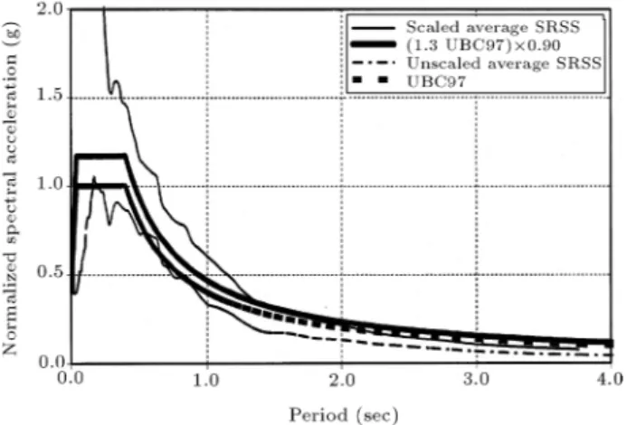
the analyses for dierent response parameters can be used for design purposes. The earthquake records are scaled, such that the average PGV of the two components equals 18 in/sec for sti soil sites [9,12]. The unscaled and the scaled lateral and transversal earthquake records used in this study are listed in Table 3. The average SRSS spectrum of the scaled records and the UBC97 design spectrum for sti soil sites are shown in Figure 5, indicating a close match, especially at longer periods, which are of main interest for base-isolated structures.
UBC97 requires that the average SRSS spectra do not fall below 1.3 times the 5 percent damped spectrum by more than 10 percent within the periods 0:5T
D to 1:25T
M. Assuming an average period of 2.0 seconds for
Figure 5.
Comparison of the unscaled and scaled average SRSS of the response spectrum of the records used for the dynamic analysis of base-isolated structural models.the eective periods of dierent base-isolation systems considered in this study (T
D
T
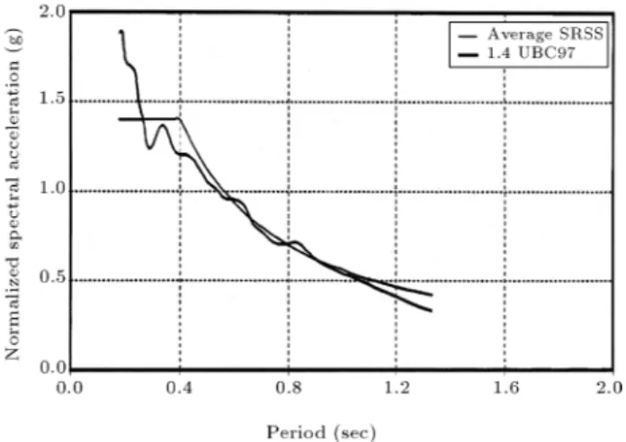
M), the scaled average SRSS spectrum of the earthquake records is also shown in Figure 5. Comparison of the results for 0.9* (1.3UBC97) and the scaled average SRSS spectrums indicates that there is a close match between the Kircher and Lashkari's scaling procedure [9] and the UBC97 design spectrum requirements. The 0.9* (1.3UBC97) spectrum represents the lower bound for the spectral values of acceleration for design purposes. The nonlinear time-history analyses on the 6-story xed base structure were also performed consid-ering bilinear behavior for dierent structural elements (10% strain hardening) of the model and simultaneous application of the aforementioned pair of earthquake records to the structural models. Again, the ground motions were scaled such that the average of the SRSS spectra (for each pair) did not fall below 1.4 times the 5 percent-damped spectrum of the UBC97 design-basis earthquake, for a period range of 0.2 T seconds to 1.5 T seconds. The ground motions scaled using this procedure are designated as \SCALED FOR FIXED BASE" in Table 3. The average response spectrum of these scaled ground motions and 1.4 times of the 5 percent-damped UBC97 design spectrum for sti soil sites, are also shown in Figure 6.
RESULTS ANDCONCLUSIONS
Extensive nonlinear time history dynamic analyses are performed using ANSYS 5.4 software [14]. For each time history analysis, the peak displacement of the base oor at the center and corner points are
deter-Figure 6.
Comparison of the scaled average SRSS response spectrum of the records used in the analyses of the xed-based structural model.mined. Also, the ratio of the maximum base-center displacement to the peak base-corner displacement, the peak base and story shear forces, the inter-story drifts and the number of columns entered into the nonlinear state per story were calculated. The mean and the mean plus one standard deviation (mean + ) values of each peak response were also determined for each isolated structure model to evaluate their variations, as well as the average value of the response. The results are presented for three sets of eective damping intervals. They are dened as the lightly-damped systems with an eective damping ratio of 6%-10%, moderately-damped with an eective damping ratio of 15%-16% and highly-damped systems that have an eective damping ratio of 26% to 30%. For the 6-story
xed base structure, the maximum base and story shear forces, inter-story drifts and number of nonlinearly behaved columns per story were also derived. Again, the mean and the mean-plus-one-standard-deviation values of the peak responses were determined for each model for comparison purposes.
In order to evaluate the UBC97 provisions for seismic isolated structures, the base and story shear forces are found using the equivalent static and dy-namic response spectrum analysis method of UBC97. The results were compared with the mean and mean-plus-one-standard-deviation of the larger peak values of the response parameter in the orthogonal directions, obtained from the nonlinear dynamic analysis. The results of the nonlinear dynamic analyses performed for dierent isolation systems are shown in Table 4. The inter-story drifts calculated from the response spectrum method were also compared with the results of nonlinear time-history analyses. Maximum base center and maximum corner displacement results of the dynamic response spectrum and time history analyses for dierent pre-dened eective damping levels were also compared. The average percentages of the nonlin-ear columns per story in the time history analyses were also determined for each of three eective damping levels.
As Figures 7 to 14 show, the static and response spectrum analysis methods of UBC97 provide a con-servative estimate of the demand oor and base shear forces for the lightly damped isolation systems (types 3, 6, and 9 with less than 10% damping). However, for the moderately and highly damped isolators, UBC97 gives a poor estimate of the base and oor shear
Table 4.
Comparison of the nonlinear time-history analysis results for the 6-story isolated and xed base structures.Isolation System Type
3
4
6
7
8
9
10
11
Fixed
Base
Base shear
force/ weight 0.198 0.180 0.130 0.119 0.104 0.098 0.086 0.077 0.301
# of nonlinear columns
in the 1st story(%)** 4 2 0 0 0 0 0 0 71 # of nonlinear columns
in the 3rd story(%) 0 10 0 0 35 0 0 0 73 # of nonlinear columns
in the 5th story(%) 74 87 50 84 100 43 94 43 99 Inter-story drift
in the 1st story(in)*** 0.361 0.345 0.321 0.350 0.390 0.276 0.276 0.224 1.785 Inter-story drift
in the 3rd story(in) 0.461 0.481 0.334 0.448 0.626 0.335 0.448 0.299 1.585 Inter-story drift
in the 5th story(in) 1.216 1.652 1.034 1.619 2.156 0.802 1.330 0.919 2.819
* and ***: The results are the mean plus one standard deviation of the results obtained from the time-history analyses. **: The results are the mean of the magnitudes obtained from the time-history analyses.
Figure 7.
Distribution of the story shear forces for base-isolation Type 3.Figure 8.
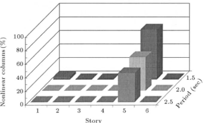
Distribution of the story shear forces for base-isolation Type 4.forces distribution (types 4, 7 and 11 with 15%-16% damping). In the case of highly damped isolators (types 8 and 10), some of the oor shear forces become larger than the base shear of the structure. The number of the columns that have performed nonlinearly during the time history analyses are shown in Figures 15 to 17. The results are another indication of inadequate estimation of UBC97 for the design shear forces of the top oors for almost all types of isolators.
As previously mentioned, the UBC97 proposed vertical distribution of the base shear were found to be severely underestimated for the highly-damped
Figure 9.
Distribution of the story shear forces for base-isolation Type 6.Figure 10.
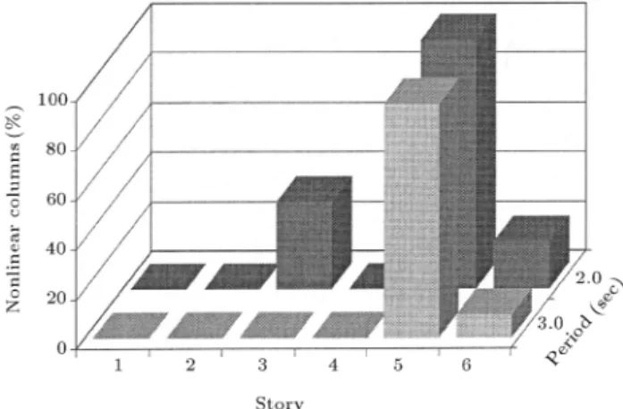
Distribution of the story shear forces for base-isolation Type 7.isolation systems. To further examine the case, a couple of 8-story superstructures with highly-damped isolation systems are considered. Extension of similar parametric studies for other base-isolation systems is left for future work, due to the large computational time needed for the dynamic nonlinear time history analyses. All the structural details for these 2 models are given in Tables 3 and 4. As Figures 18 and 19 show, the demand shear forces induced in the superstructure are much larger than their estimated values by UBC97. The number of nonlinear columns for the upper oors has also increased, as Figure 20 indicates. The eect
Figure 11.
Distribution of the story shear forces for base-isolation Type 8.Figure 12.
Distribution of story shear forces for base-isolation Type 9.of higher modes can be one of the main reasons for this observation. In a previous study, considering a concentrated force,F
t= 0 :5TV
S, on the top oor led to acceptable results for the story shear forces [15].
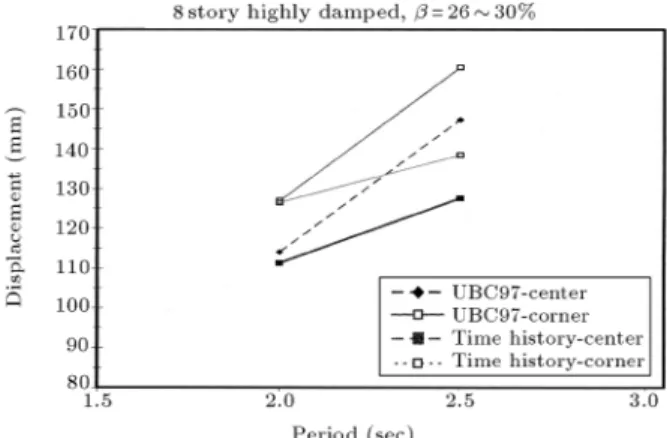
For the maximum center and corner displace-ments of the base oor in 6 and 8 story base-isolated structures, with any level of damping, UBC97 provides an appropriate estimate, as Figures 21 to 24 show. In all of the above cases, the UBC97 equivalent static method gives a better estimate for the shear force distribution over the height of the superstructure, even though the UBC97 does not allow the application of the equivalent static method for designing the base-isolated structures with more than 4 stories. Also, the
Figure 13.
Distribution of story shear forces for base-isolation Type 10.Figure 14.
Distribution of story shear forces for base-isolation Type 11.Figure 15.
Percentage of nonlinear columns for lightly-damped isolation systems.Figure 16.
Percentage of nonlinear columns for moderately-damped isolation systems.Figure 17.
Percentage of nonlinear columns for highly-damped isolation systems.Figure 18.
Distribution of story shear forces for base-isolation Type 8E in 8-story structural models.Figure 19.
Distribution of story shear forces for base-isolation Type 10E, in 8-story structural models.Figure 20.
Percentage of nonlinear columns for highly-damped isolation systems in 8-story models.Figure 21.
Results of base center and corner displacements for lightly-damped systems in 6-story models.Figure 22.
Results of base center and cornerdisplacements for moderately-damped systems in 6-story models.
Figure 23.
Results of base center and corner displacements for highly-damped systems in 6-story models.Figure 24.
Results of base center and corner displacements for highly-damped systems in 8-story models.results of the time-history analyses performed on the 6-story xed base structure were used to compare the seismic behavior of two systems. Table 3 summarizes the results of the time-history analysis on the 6-story isolated and xed base structure.
CONCLUSIONS
In order to evaluate the UBC97 provisions for seismic isolated structures, dierent 6 and 8-story, 3-D base-isolated structural models with LRB isolators are considered. Extensive nonlinear dynamic analyses are performed for 8 types of LRB isolator, using appro-priately normalized earthquake accelerograms recorded on S
A and S
B soil proles. Both the superstructure and the isolators are allowed to behave nonlinearly, in order to evaluate the seismic induced demand shear forces in dierent oors. The results are presented for three sets of lightly-damped, moderately-damped and highly-damped systems, with eective damping ratio intervals of 6%-10%, 15%-16% and 26% to 30%, respectively. The base and story shear forces obtained from the equivalent static analyses (just for comparison purposes) and the dynamic response spectrum anal-yses were compared with the mean and mean-plus-one-standard-deviation of peak results obtained from nonlinear time-history analyses. The comparison of results indicates that the base shear force recommended by UBC97 is reasonably accurate for all the isolation systems under investigation. The vertical distribution of the base shear force estimated by response spectrum analysis is not appropriate for higher stories. In the case of highly damped isolation systems, this problem was found to be of more severity. In fact, the design lateral shear force for the higher stories of the structural models was underestimated by UBC guidelines. This led to large inter-story drifts for these stories and a large amount of nonlinear behavior for a considerable percentage of columns in these stories. Taking into account that the same results were previously drawn for 4-story isolated structures, it can be concluded that neither the static (for up to 4 stories) nor the response spectrum analysis procedures prescribed by UBC97 are capable of proposing an appropriate distribution of elastic forces for dierent oors in highly-damped base-isolated structures. The base displacement estimated by UBC97 is suciently accurate for moderately and highly damped isolation systems, but seems to be rather conservative for lightly damped systems. REFERENCES
1. Su, L. and Ahmadi, G.A. \Comparative study of performance of various base isolation systems, Part 1: Shear beam structures", Earthquake Eng. and Struc-tural Dynamics,
18
, pp 11-32 (1989).2. Fan, F., Ahmadi, G., Mostaghel, N. and Tadjbakhsh, I.G. \Performance analysis of seismic base isolation systems for a multi-story building",Soil Dynamics and Earthquake Eng.,
10
(3) (1991).3. Seismology Committee of the Structural Engineers As-sociation of North California, \Recommended lateral
force requirements and commentary", Sacramento, CA, USA (1990).
4. \Structural Engineers Association of North California (SEAONC)",Tentative Seismic Isolation Design Re-quirements, San Francisco, CA, USA (1986).
5. International Conference of Building Ocials, \Uni-form building code", Whittier, California, USA (1991). 6. International Conference of Building Ocials, \Uni-form building code", Whittier, California, USA (1994). 7. International Conference of Building Ocials, \Uni-form building code", Whittier, California, USA (1997). 8. American Association of State Highway Transporta-tion Ocials (AASHTO), \Guide specications for seismic isolation design", Washington D.C., USA (1991).
9. Kircher, C.A. and Lashkary, B. \Statistical evaluation of nonlinear response of seismic isolation systems", Re-port No. JBA 109-070, J.R. Benjamin and Associates Inc., Mountain View, CA, USA (1989).
10. Mokha, A., Constantinou, M.C. and Reinhorn, A.M. \Verication of friction model of Teon bearing un-der triaxial load",Journal of Structural Engineering, ASCE, pp 240 (1993).
11. Constantinou, M.C, Winter, C.W. and Theodossiou, D. \Evaluation of SEAOC/UBC analysis procedures, Part 2: Flexible superstructure",ATC-17-1, pp 161-172 (1993).
12. Winters, C.W. and Constantinou, M.C. \Evaluation of response spectrum procedure of SEAOC/UBC for seismic isolated structures", Report No. NCEER-93-XXXX, National Center for Earthquake Engineering Research, State University of New York, Bualo, NY, USA (1993).
13. Lin, A.N. and Shenton, H.W. \Seismic performance of xed base and base-isolated steel frames",Journal of Engineering Mechanics, ASCE,
118
(55), pp 921-941 (1992).14. ANSYS, A Numerical Analysis Software Prepared by Swanson Analysis Systems Inc., Hauston, PA, USA. 15. Rofooei, F.R. and Saadatnia, H. \Evaluation of the
SEAOC/UBC97 provisions for the tall base-isolated structures",Esteghlal Journal of Engineering, Isfahan University of Technology,