Integrated Management Module I
User's Guide
Integrated Management Module I
User's Guide
Contents
Tables
. . . v
Chapter 1. Introduction . . . 1
IMM features . . . 3
Upgrading from IMM Standard to IMM Premium 5 Comparing the IMM to other systems-management hardware in System x servers . . . 5
Using IMM with a BladeCenter advanced management module . . . 8
Web browser and operating-system requirements . . 8
Notices used in this book . . . 9
Chapter 2. Opening and using the IMM
web interface . . . 11
Accessing the IMM web interface . . . 11
Setting up the IMM network connection through the IBM System x Server Firmware Setup utility . 11 Logging in to the IMM . . . 14
IMM action descriptions . . . 15
Chapter 3. Configuring the IMM . . . . 19
Setting system information . . . 20
Setting server timeouts . . . 21
Setting the IMM date and time . . . 22
Synchronizing clocks in a network. . . 23
Disabling the USB in-band interface . . . 23
Creating a login profile . . . 25
Deleting a login profile . . . 29
Configuring the global login settings . . . 29
Configuring remote alert settings . . . 30
Configuring remote alert recipients . . . 30
Configuring global remote alert settings . . . . 32
Configuring SNMP alert settings . . . 33
Configuring serial port settings . . . 33
Configuring serial-to-Telnet or SSH redirection . . 34
Configuring port assignments . . . 35
Configuring network interfaces . . . 36
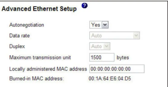
Configuring the Ethernet settings . . . 37
Configuring the IPv4 settings . . . 39
Configuring the IPv6 settings . . . 41
Configuring network protocols . . . 41
Configuring SNMP . . . 42
Configuring DNS . . . 43
Configuring Telnet . . . 44
Configuring SMTP . . . 44
Configuring LDAP . . . 45
User schema example . . . 45
Novell eDirectory schema view . . . 46
Browsing the LDAP server . . . 53
Microsoft Windows Server 2003 Active Directory schema view . . . 55
Configuring the LDAP client . . . 60
Configuring security . . . 76
Enabling data encryption . . . 77
Securing the web server, IBM Systems Director, and secure LDAP . . . 77
SSL certificate . . . 78
SSL server certificate management . . . 78
Enabling SSL for the secure web server or IBM Systems Director over HTTPS . . . 82
SSL client certificate management . . . 83
SSL client trusted certificate management . . . 83
Enabling SSL for the LDAP client . . . 83
Cryptography management . . . 84
Configuring the Secure Shell server . . . 84
Generating a Secure Shell server key . . . 84
Enabling the Secure Shell server . . . 85
Using the Secure Shell server . . . 85
Restoring and modifying your IMM configuration 85 Using the configuration file . . . 86
Backing up your current configuration . . . . 86
Restoring and modifying your IMM configuration . . . 87
Restoring defaults . . . 88
Restarting IMM . . . 88
Scalable partitioning . . . 88
Service Advisor feature . . . 88
Configuring Service Advisor. . . 89
Using Service Advisor . . . 91
Logging off . . . 93
Chapter 4. Monitoring server status . . 95
Viewing system status . . . 95
Viewing the Virtual Light Path . . . 99
Viewing the event logs . . . 99
Viewing the system-event log from the web interface . . . 100
Viewing event logs from the Setup utility . . . 101
Viewing event logs without restarting the server 102 Viewing vital product data . . . 103
Chapter 5. Performing IMM tasks . . . 105
Viewing server power and restart activity . . . . 105
Controlling the power status of a server . . . . 106
Remote presence . . . 107
Updating your IMM firmware and Java or ActiveX applet . . . 107
Enabling the remote presence function . . . . 108
Remote control . . . 108
Remote control screen capture . . . 110
Remote control Video Viewer view modes . . . 110
Remote control video color mode . . . 111
Remote control keyboard support. . . 111
Remote control mouse support . . . 113
Remote power control . . . 114
Viewing performance statistics. . . 114
Starting Remote Desktop Protocol . . . 115
Remote disk . . . 115
Updating firmware . . . 117
Resetting the IMM with the Setup utility . . . . 118
Managing tools and utilities with IMM and IBM System x Server Firmware . . . 119
Using IPMItool . . . 120
Using OSA System Management Bridge . . . 120
Using IBM Advanced Settings Utility . . . . 120
Using IBM Flash utilities . . . 120
Other methods for managing the IMM . . . . 121
Chapter 6. LAN over USB . . . 123
Potential conflicts with the LAN over USB interface 123 Resolving conflicts with the IMM LAN over USB interface . . . 123
Configuring the LAN over USB interface manually 124 Installing device drivers . . . 124
Installing the Windows IPMI device driver . . 124
Installing the LAN over USB Windows device driver . . . 124
Installing the LAN over USB Linux device driver . . . 125
Chapter 7. Command-line interface
127
Managing the IMM with IPMI. . . 127Accessing the command line . . . 127
Logging in to the command-line session . . . . 127
Command syntax . . . 128
Features and limitations . . . 128
Utility commands . . . 129
exit command . . . 129
help command . . . 129
history command . . . 129
Monitor commands . . . 130
clearlog command . . . 130
fans command . . . 130
readlog command . . . 130
syshealth command . . . 131
temps command . . . 131
volts command . . . 132
vpd command . . . 132
Server power and restart control commands . . . 132
power command . . . 132
reset command . . . 133
Serial redirect command . . . 133
console command . . . 133
Configuration commands . . . 133
dhcpinfo command . . . 134
dns command . . . 134
gprofile command . . . 135
ifconfig command . . . 136
ldap command . . . 138
ntp command . . . 139
passwordcfg command . . . 140
portcfg command . . . 141
timeouts command . . . 143
usbeth command . . . 144
users command . . . 144
IMM control commands . . . 145
clearcfg command . . . 145
clock command. . . 146
identify command . . . 146
resetsp command . . . 146
update command . . . 147
Service Advisor commands . . . 147
autoftp command . . . 148
chconfig command . . . 148
chlog command . . . 150
chmanual command . . . 150
events command . . . 150
sdemail command . . . 151
Appendix A. Getting help and
technical assistance . . . 153
Before you call . . . 153
Using the documentation . . . 154
Getting help and information from the World Wide Web . . . 154
How to send DSA data to IBM . . . 154
Creating a personalized support web page . . . 154
Software service and support . . . 155
Hardware service and support . . . 155
IBM Taiwan product service . . . 155
Appendix B. Notices . . . 157
Trademarks . . . 157
Important notes . . . 158
Particulate contamination . . . 159
Documentation format . . . 160
Telecommunication regulatory statement . . . . 160
Electronic emission notices . . . 160
Federal Communications Commission (FCC) statement. . . 160
Industry Canada Class A emission compliance statement. . . 161
Avis de conformité à la réglementation d'Industrie Canada . . . 161
Australia and New Zealand Class A statement 161 European Union EMC Directive conformance statement. . . 161
Germany Class A statement . . . 162
Japan VCCI Class A statement. . . 163
Korea Communications Commission (KCC) statement. . . 163
Russia Electromagnetic Interference (EMI) Class A statement . . . 163
People's Republic of China Class A electronic emission statement . . . 163
Tables
1. Comparison of the IMM features and combined BMC and Remote Supervisor Adapter II
features in System x servers . . . 5
2. IMM actions . . . 15
3. Reserved port numbers . . . 36
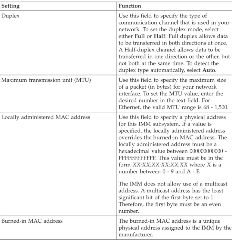
4. Settings on the Advanced Ethernet Setup page 38 5. User to Group mapping . . . 46
6. Permission bits . . . 50
7. Example UserLevelAuthority attributes and descriptions . . . 51
8. UserAuthorityLevel assignments to user groups . . . 52
9. Checking authority levels and group membership . . . 60
10. Miscellaneous parameters . . . 63
11. Group profiles information . . . 64
12. Miscellaneous parameters . . . 69
13. Permission bits . . . 74
14. IMM SSL connection support . . . 77
15. Contact Information. . . 89
16. Methods for viewing event logs . . . 103
17. Machine-level vital product data . . . 104
18. Component-level vital product data . . . . 104
19. Component activity log . . . 104
20. IMM, UEFI, and DSA firmware vital product data. . . 104
Chapter 1. Introduction
The integrated management module (IMM) consolidates the service processor functionality, Super I/O, video controller, and remote presence capabilities in a single chip on the server system board. The IMM replaces the baseboard
management controller (BMC) and Remote Supervisor Adapter II in IBM®System x servers.
Before the IMM was used in IBM servers, the baseboard management controller (BMC) and basic input/output system (BIOS) were the standard
systems-management hardware and firmware. System x servers used BMC service processors to manage the interface between systems-management software and platform hardware. The Remote Supervisor Adapter II and Remote Supervisor Adapter II Slimline were optional controllers for out-of-band server management.
Important:Although the IMM is standard in some IBM BladeCenter products and IBM blade servers, the BladeCenter advanced management module remains the primary management module for systems-management functions and
keyboard/video/mouse (KVM) multiplexing for BladeCenter and blade servers. The contents that are related to IMM Web Interface and the Command-line Interface do not apply to IBM BladeCenter and blade servers. Users who wish to configure the IMM settings on blade servers should use the Advanced Settings Utility (ASU) on the blade server to perform those actions.
The IMM offers several improvements over the combined functionality of the BMC and the Remote Supervisor Adapter II:
v Choice of dedicated or shared Ethernet connection. The dedicated Ethernet connection is not available on blade servers or some System x servers.
Note: A dedicated systems-management network port might not be available on your server. If your hardware does not have a dedicated network port, theshared setting is the only IMM setting available.
v One IP address for both the Intelligent Platform Management Interface (IPMI) and the service processor interface. The feature does not apply to blade servers. v Embedded Dynamic System Analysis (DSA).
v Ability to locally or remotely update other entities without requiring a server restart to initiate the update process.
v Remote configuration with Advanced Settings Utility (ASU). The feature does not apply to blade servers.
v Capability for applications and tools to access the IMM either in-band or out-of-band. Only the in-band IMM connection is supported on blade servers. v Enhanced remote-presence capabilities. The feature does not apply to blade
servers.
IBM System x® Server Firmware is IBM's implementation of Unified Extensible Firmware Interface (UEFI). It replaces BIOS in System x servers and IBM blade servers. The BIOS was the standard firmware code that controlled basic hardware operations, such as interactions with diskette drives, hard disk drives, and the keyboard. IBM System x Server Firmware offers several features that BIOS does not, including UEFI 2.1 compliance, iSCSI compatibility, Active Energy Manager
technology, and enhanced reliability and service capabilities. The Setup utility provides server information, server setup, customization compatibility, and establishes the boot device order.
Notes:
v IBM System x Server Firmware is often called server firmware, and occasionally called UEFI, in this document.
v IBM System x Server Firmware is fully compatible with non-UEFI operating systems.
v For more information about using IBM System x Server Firmware, see the documentation that came with your server.
This document explains how to use the functions of the IMM in an IBM server. The IMM works with IBM System x Server Firmware to provide
systems-management capability for System x and BladeCenter servers.
This document does not contain explanations of errors or messages. IMM errors and messages are described in theProblem Determination and Service Guide that came with your server. To find the latest version of this document or the IBM white paper Transitioning to UEFI and IMMon the IBM®Support Portal, complete the following steps.
Note: The first time you access the IBM Support Portal, you must choose the product category, product family, and model numbers for your server. The next time you access the IBM Support Portal, the products you selected initially are preloaded by the website, and only the links for your products are displayed. To change or add to your product list, click theManage my product listslink. Changes are made periodically to the IBM website. Procedures for locating firmware and documentation might vary slightly from what is described in this document.
1. Go to http://www.ibm.com/support/entry/portal.
2. UnderChoose your products, selectBrowse for a productand expand
Hardware.
3. Depending on your type of server, clickSystems>System xorSystems>
BladeCenter, and check the box for your server or servers. 4. UnderChoose your task, clickDocumentation.
5. UnderSee your results, clickView your page. 6. In the Documentation box, clickMore results.
7. In the Category box, select theIntegrated Management Module (IMM)check box. Links to the IMM and UEFI documentation appear.
If firmware updates are available, you can download them from the IBM website. The IMM might have features that are not described in the documentation, and the documentation might be updated occasionally to include information about those features, or technical updates might be available to provide additional information that is not included in the IMM documentation.
preloaded by the website, and only the links for your products are displayed. To change or add to your product list, click theManage my product listslink. Changes are made periodically to the IBM website. Procedures for locating firmware and documentation might vary slightly from what is described in this document.
1. Go to http://www.ibm.com/support/entry/portal.
2. UnderChoose your products, selectBrowse for a productand expand
Hardware.
3. Depending on your type of server, clickSystems> System xorSystems>
BladeCenter, and check the box for your server or servers. 4. UnderChoose your task, clickDownloads.
5. UnderSee your results, clickView your page.
6. In the Flashes & alerts box, click the link for the applicable download or click
More resultsto see additional links.
IMM features
The IMM provides the following functions:
v Around-the-clock remote access and management of your server v Remote management independent of the status of the managed server v Remote control of hardware and operating systems
v Web-based management with standard web browsers
IMM provides two types of IMM functionality: IMM Standard features and IMM Premium features. For information about the type of IMM hardware in your server, see the documentation that came with the server.
IMM Standard features
Note: Some the following features do not apply to blade servers. v Access to critical server settings
v Access to server vital product data (VPD)
v Advanced Predictive Failure Analysis (PFA) support v Automatic notification and alerts
v Continuous health monitoring and control
v Choice of a dedicated or shared Ethernet connection (if applicable).
Note: A dedicated systems-management network port might not be available on your server.
v Domain Name System (DNS) server support
v Dynamic Host Configuration Protocol (DHCP) support v E-mail alerts
v Embedded Dynamic System Analysis (DSA) v Enhanced user authority levels
v LAN over USB for in-band communications to the IMM
v Event logs that are time stamped, saved on the IMM, and can be attached to e-mail alerts
v Industry-standard interfaces and protocols v OS watchdogs
v Remote configuration through Advanced Settings Utility (ASU) v Remote firmware updating
v Remote power control
v Seamless remote accelerated graphics v Secure web server user interface v Serial over LAN
v Server console redirection
v Simple Network Management Protocol (SNMP) support
v User authentication using a secure connection to a Lightweight Directory Access Protocol (LDAP) server
IMM Premium features
Note: Some the following features do not apply to blade servers. v Access to critical server settings
v Access to server vital product data (VPD)
v Advanced Predictive Failure Analysis (PFA) support v Automatic notification and alerts
v Continuous health monitoring and control
v Choice of a dedicated or shared Ethernet connection (if applicable).
Note: A dedicated systems-management network port might not be available on your server.
v Domain Name System (DNS) server support
v Dynamic Host Configuration Protocol (DHCP) support v E-mail alerts
v Embedded Dynamic System Analysis (DSA) v Enhanced user authority levels
v LAN over USB for in-band communications to the IMM
v Event logs that are time stamped, saved on the IMM, and can be attached to e-mail alerts
v Industry-standard interfaces and protocols v OS watchdogs
v Remote configuration through Advanced Settings Utility (ASU) v Remote firmware updating
v Remote power control
v Seamless remote accelerated graphics v Secure web server user interface v Serial over LAN
v Server console redirection
v Simple Network Management Protocol (SNMP) support
Note: The following features of the Remote Supervisor Adapter II are not in the IMM:
v Display of server MAC addresses v Multiple NTP server entries
Upgrading from IMM Standard to IMM Premium
If your server has IMM Standard functionality, you can upgrade to IMM Premium by purchasing and installing a virtual media key on your server system board. No new firmware is required.
To order a virtual media key, go to http://www.ibm.com/systems/x/ newgeneration.
Note: For information about installing the virtual media key, see the documentation that came with your server.
If you need help with your order, call the toll-free number that is listed on the retail parts page, or contact your local IBM representative for assistance.
Comparing the IMM to other systems-management hardware
in System x servers
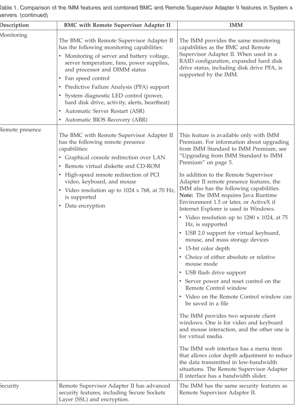
The following table compares IMM features with BMC and Remote Supervisor Adapter II features in System x servers.
Note: Like the BMC, the IMM uses the standard IPMI specification.
Table 1. Comparison of the IMM features and combined BMC and Remote Supervisor Adapter II features in System x servers
Description BMC with Remote Supervisor Adapter II IMM Network connections BMC uses a network connection that is
shared with a server and an IP address that is different from the Remote Supervisor Adapter II IP address.
Remote Supervisor Adapter II uses a dedicated systems-management network connection and an IP address that is different from the BMC IP address.
The IMM provides both BMC and Remote Supervisor Adapter II functionality through the same network connection. One IP address is used for both. If your server has a dedicated systems-management network port, you can choose either a dedicated or a shared network connection.
Note: A dedicated systems-management network port might not be available on your server. If your hardware does not have a dedicated network port, thesharedsetting is the only IMM setting available.
Update capabilities Each server requires a unique update for BMC and Remote Supervisor Adapter II. BIOS and diagnostic tools can be updated in-band.
One IMM firmware image can be used for all of the applicable servers.
The IMM firmware, System x server firmware, and Dynamic System Analysis (DSA) firmware can be updated both in-band and out-of-band.
The IMM can update itself, the server firmware, and the DSA firmware either locally or remotely without requiring the server to be restarted to initiate the update process.
Table 1. Comparison of the IMM features and combined BMC and Remote Supervisor Adapter II features in System x servers (continued)
Description BMC with Remote Supervisor Adapter II IMM Configuration
capabilities
Configuration changes with the ASU are available only in-band. The system requires separate configurations for BMC, Remote Supervisor Adapter II, and BIOS.
The ASU can run either in-band or
out-of-band and can configure both the IMM and the server firmware. With the ASU, you can also modify the boot order, iSCSI, and VPD (machine type, serial number, UUID, and asset ID).
The server firmware configuration settings are kept by the IMM. Therefore, you can make server firmware configuration changes while the server is turned off or while the operating system is running, and those changes are effective the next time the server is started.
The IMM configuration settings can be configured in-band or out-of-band through the following IMM user interfaces:
v Web interface
v Command-line interface v IBM Systems Director interface v SNMP
Operating-system screen capture
Screen captures are performed by the Remote Supervisor Adapter II when operating-system failures occur. The display of screen captures requires a Java applet.
This feature is available only with IMM Premium. For information about upgrading from IMM Standard to IMM Premium, see “Upgrading from IMM Standard to IMM Premium” on page 5.
Screen captures are displayed directly by the web browser without the need for a Java applet.
Error logging The BMC provides a BMC system-event log (IPMI event log).
The Remote Supervisor Adapter II provides a text-based log that includes descriptions of events that are reported by the BMC. This log also contains any information or events detected by the Remote Supervisor Adapter II itself.
The IMM has two event logs:
1. The system-event log is available through the IPMI interface.
2. The chassis-event log is available through the other IMM interfaces. The chassis-event log displays text messages that are generated using the Distributed Management Task Force specifications DSP0244 and DSP8007.
Note: For an explanation of a specific event or message, see theProblem Determination and Service Guidethat came with your server.
Table 1. Comparison of the IMM features and combined BMC and Remote Supervisor Adapter II features in System x servers (continued)
Description BMC with Remote Supervisor Adapter II IMM Monitoring
The BMC with Remote Supervisor Adapter II has the following monitoring capabilities: v Monitoring of server and battery voltage,
server temperature, fans, power supplies, and processor and DIMM status
v Fan speed control
v Predictive Failure Analysis (PFA) support v System diagnostic LED control (power,
hard disk drive, activity, alerts, heartbeat) v Automatic Server Restart (ASR)
v Automatic BIOS Recovery (ABR)
The IMM provides the same monitoring capabilities as the BMC and Remote Supervisor Adapter II. When used in a RAID configuration, expanded hard disk drive status, including disk drive PFA, is supported by the IMM.
Remote presence
The BMC with Remote Supervisor Adapter II has the following remote presence
capabilities:
v Graphical console redirection over LAN v Remote virtual diskette and CD-ROM v High-speed remote redirection of PCI
video, keyboard, and mouse
v Video resolution up to 1024 x 768, at 70 Hz, is supported
v Data encryption
This feature is available only with IMM Premium. For information about upgrading from IMM Standard to IMM Premium, see “Upgrading from IMM Standard to IMM Premium” on page 5.
In addition to the Remote Supervisor Adapter II remote presence features, the IMM also has the following capabilities. Note: The IMM requires Java Runtime Environment 1.5 or later, or ActiveX if Internet Explorer is used in Windows. v Video resolution up to 1280 x 1024, at 75
Hz, is supported
v USB 2.0 support for virtual keyboard, mouse, and mass storage devices v 15-bit color depth
v Choice of either absolute or relative mouse mode
v USB flash drive support
v Server power and reset control on the Remote Control window
v Video on the Remote Control window can be saved in a file
The IMM provides two separate client windows. One is for video and keyboard and mouse interaction, and the other one is for virtual media.
The IMM web interface has a menu item that allows color depth adjustment to reduce the data transmitted in low-bandwidth situations. The Remote Supervisor Adapter II interface has a bandwidth slider. Security Remote Supervisor Adapter II has advanced
security features, including Secure Sockets Layer (SSL) and encryption.
The IMM has the same security features as Remote Supervisor Adapter II.
Table 1. Comparison of the IMM features and combined BMC and Remote Supervisor Adapter II features in System x servers (continued)
Description BMC with Remote Supervisor Adapter II IMM Serial redirection
The IPMI Serial over LAN (SOL) function is a standard capability of the BMC.
The Remote Supervisor Adapter II provides the ability to redirect server serial data to a Telnet or SSH session.
Note: This feature is not available on some servers.
The COM1 port is used for SOL on System x servers. COM1 is configurable only through the IPMI interface.
The COM2 port is used for serial redirection through Telnet or SSH. COM2 is
configurable through all of the IMM interfaces except for the IPMI interface. The COM2 port is used for SOL on blade servers.
Both COM port configurations are limited to 8 data bits, null parity, 1 stop bit, and a baud rate choice of 9600, 19200, 38400, 57600, 115200, or 230400.
On blade servers, the COM2 port is an internal COM port with no external access. IPMI serial-port sharing is not possible on blade servers.
On rack-mounted and tower servers, the IMM COM2 port is an internal COM port with no external access.
SNMP SNMP support is limited to SNMPv1. The IMM supports SNMPv1 and SNMPv3.
Using IMM with a BladeCenter advanced management module
The BladeCenter advanced management module is the standardsystems-management interface in IBM BladeCenter and IBM blade servers. Although the IMM is now included in some IBM BladeCenter and IBM blade servers, the advanced management module remains the management module for systems-management functions and keyboard, video, and mouse (KVM)
multiplexing for BladeCenter and blade servers. The external network interfaces to the IMM are not available in BladeCenter.
There is no external network access to the IMM on blade servers. The advanced management module must be used for remote management of blade servers. The IMM replaces the functionality of the BMC and the Concurrent Keyboard, Video and Mouse (cKVM) option card in past blade server products.
Web browser and operating-system requirements
The IMM web interface requires the Java™Plug-in 1.5 or later (for the remote presence feature) and one of the following web browsers:
v Microsoft Internet Explorer version 6.0, 7.0, or 8.0 with the latest Service Pack. Versions later than 8.0 are not supported.
v Microsoft Windows Server 2008 v Microsoft Windows Server 2003
v Red Hat Enterprise Linux versions 4.0 and 5.0 v SUSE Linux version 10.0
v Novell NetWare 6.5
Note: The IMM web interface does not support the double-byte character set (DBCS) languages.
Notices used in this book
The following notices are used in the documentation:
v Note:These notices provide important tips, guidance, or advice.
v Important:These notices provide information or advice that might help you avoid inconvenient or problem situations.
v Attention:These notices indicate potential damage to programs, devices, or data. An attention notice is placed just before the instruction or situation in which damage might occur.
Chapter 2. Opening and using the IMM web interface
The IMM combines service processor functions, a video controller, and remote presence function (when an optional virtual media key is installed) in a single chip. To access the IMM remotely by using the IMM web interface, you must first log in. This chapter describes the login procedures and the actions that you can perform from the IMM web interface.
Accessing the IMM web interface
The IMM supports static and Dynamic Host Configuration Protocol (DHCP) IPv4 addressing. The default static IPv4 address assigned to the IMM is 192.168.70.125. The IMM is initially configured to attempt to obtain an address from a DHCP server, and if it cannot, it uses the static IPv4 address.
IMM also supports IPv6, but the IMM does not have a fixed static IPv6 IP address by default. For initial access to the IMM in an IPv6 environment, you can either use the IPv4 IP address or the IPv6 link-local address. The IMM generates a unique link-local IPv6 address, which is shown in the IMM web interface on the Network Interfaces page. The link-local IPv6 address has the same format as the following example.
fe80::21a:64ff:fee6:4d5
When you access the IMM, the following IPv6 conditions are set as default: v Automatic IPv6 address configuration is enabled.
v IPv6 static IP address configuration is disabled. v DHCPv6 is enabled.
v Stateless Auto-configuration is enabled.
The IMM provides the choice of using a dedicated systems-management network connection (if applicable) or one that is shared with the server. The default connection for rack-mounted and tower servers is to use the dedicated systems-management network connector.
Note: A dedicated systems-management network port might not be available on your server. If your hardware does not have a dedicated network port, the shared setting is the only IMM setting available.
Setting up the IMM network connection through the IBM
System x Server Firmware Setup utility
After you start the server, you can use the Setup utility to select an IMM network connection. The server with the IMM hardware must be connected to a Dynamic Host Configuration Protocol (DHCP) server, or the server network must be configured to use the IMM static IP address. To set up the IMM network connection through the Setup utility, complete the following steps:
1. Turn on the server. The IBM System x Server Firmware welcome screen is displayed.
Note: Approximately 2 minutes after the server is connected to ac power, the power-control button becomes active.
2. When the prompt<F1> Setupis displayed, press F1. If you have set both a power-on password and an administrator password, you must type the administrator password to access the full Setup utility menu.
3. From the Setup utility main menu, select System Settings. 4. On the next screen, selectIntegrated Management Module. 5. On the next screen, selectNetwork Configuration.
6. Highlight DHCP Control. There are three IMM network connection choices in theDHCP Controlfield:
v Static IP v DHCP Enabled
7. Select one of the network connection choices.
8. If you choose to use a static IP address, you must specify the IP address, the subnet mask, and the default gateway.
9. You can also use the Setup utility to select a dedicated network connection (if your server has a dedicated network port) or a shared IMM network
connection.
Notes:
v A dedicated systems-management network port might not be available on your server. If your hardware does not have a dedicated network port, the sharedsetting is the only IMM setting available. On theNetwork
Configurationscreen, selectDedicated(if applicable) orSharedin the
Network Interface Portfield.
v To find the locations of the Ethernet connectors on your server that are used by the IMM, see the documentation that came with your server.
10. Select Save Network Settings. 11. Exit from the Setup utility.
Notes:
v You must wait approximately 1 minute for changes to take effect before the server firmware is functional again.
v You can also configure the IMM network connection through the IMM web interface. For more information, see “Configuring network interfaces” on page 36.
Logging in to the IMM
Important: The IMM is set initially with a user name ofUSERIDand password of
PASSW0RD(with a zero, not the letter O). This default user setting has Supervisor access. Change this default password during your initial configuration for enhanced security.
To access the IMM through the IMM web interface, complete the following steps: 1. Open a web browser. In the address or URL field, type the IP address or host
name of the IMM server to which you want to connect.
2. Type your user name and password in the IMM Login window. If you are using the IMM for the first time, you can obtain your user name and password from your system administrator. All login attempts are documented in the event log. Depending on how your system administrator configured the user ID, you might need to enter a new password.
3. On the Welcome webpage, select a timeout value from the drop-down list in the field that is provided. If your browser is inactive for that number of minutes, the IMM logs you off the web interface.
Note: Depending on how your system administrator configured the global login settings, the timeout value might be a fixed value.
4. ClickContinueto start the session. The browser opens the System Status page, which gives you a quick view of the server status and the server health
For descriptions of the actions that you can perform from the links in the left navigation pane of the IMM web interface, see “IMM action descriptions.” Then, go to Chapter 3, “Configuring the IMM,” on page 19.
IMM action descriptions
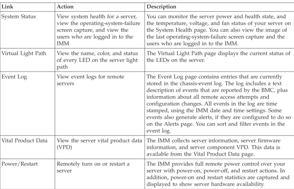
Table 2 lists the actions that are available when you are logged in to the IMM.
Table 2. IMM actions
Link Action Description
System Status View system health for a server, view the operating-system-failure screen capture, and view the users who are logged in to the IMM
You can monitor the server power and health state, and the temperature, voltage, and fan status of your server on the System Health page. You can also view the image of the last operating-system-failure screen capture and the users who are logged in to the IMM.
Virtual Light Path View the name, color, and status of every LED on the server light path
The Virtual Light Path page displays the current status of the LEDs on the server.
Event Log View event logs for remote servers
The Event Log page contains entries that are currently stored in the chassis-event log. The log includes a text description of events that are reported by the BMC, plus information about all remote access attempts and configuration changes. All events in the log are time stamped, using the IMM date and time settings. Some events also generate alerts, if they are configured to do so on the Alerts page. You can sort and filter events in the event log.
Vital Product Data View the server vital product data (VPD)
The IMM collects server information, server firmware information, and server component VPD. This data is available from the Vital Product Data page.
Power/Restart Remotely turn on or restart a server
The IMM provides full remote power control over your server with power-on, power-off, and restart actions. In addition, power-on and restart statistics are captured and displayed to show server hardware availability.
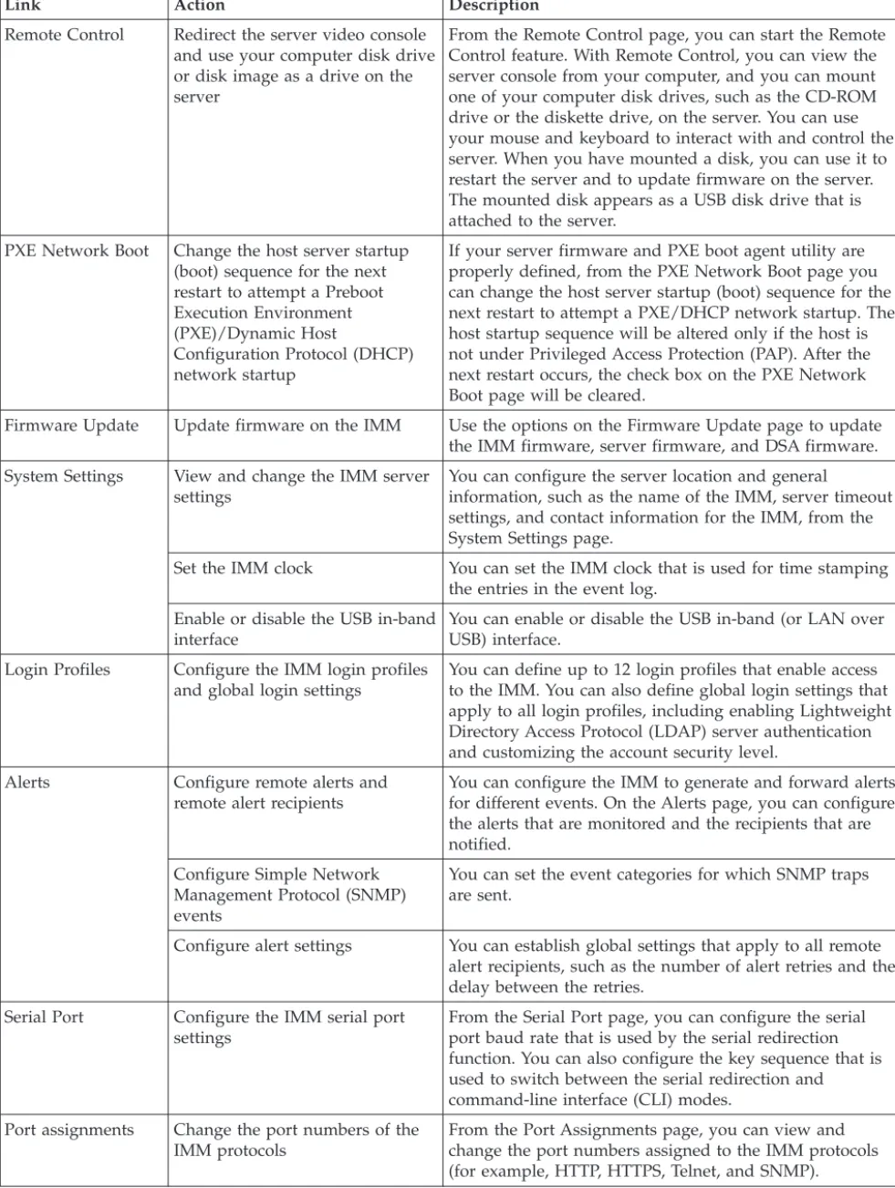
Table 2. IMM actions (continued)
Link Action Description
Remote Control Redirect the server video console and use your computer disk drive or disk image as a drive on the server
From the Remote Control page, you can start the Remote Control feature. With Remote Control, you can view the server console from your computer, and you can mount one of your computer disk drives, such as the CD-ROM drive or the diskette drive, on the server. You can use your mouse and keyboard to interact with and control the server. When you have mounted a disk, you can use it to restart the server and to update firmware on the server. The mounted disk appears as a USB disk drive that is attached to the server.
PXE Network Boot Change the host server startup (boot) sequence for the next restart to attempt a Preboot Execution Environment (PXE)/Dynamic Host
Configuration Protocol (DHCP) network startup
If your server firmware and PXE boot agent utility are properly defined, from the PXE Network Boot page you can change the host server startup (boot) sequence for the next restart to attempt a PXE/DHCP network startup. The host startup sequence will be altered only if the host is not under Privileged Access Protection (PAP). After the next restart occurs, the check box on the PXE Network Boot page will be cleared.
Firmware Update Update firmware on the IMM Use the options on the Firmware Update page to update the IMM firmware, server firmware, and DSA firmware. System Settings View and change the IMM server
settings
You can configure the server location and general
information, such as the name of the IMM, server timeout settings, and contact information for the IMM, from the System Settings page.
Set the IMM clock You can set the IMM clock that is used for time stamping the entries in the event log.
Enable or disable the USB in-band interface
You can enable or disable the USB in-band (or LAN over USB) interface.
Login Profiles Configure the IMM login profiles and global login settings
You can define up to 12 login profiles that enable access to the IMM. You can also define global login settings that apply to all login profiles, including enabling Lightweight Directory Access Protocol (LDAP) server authentication and customizing the account security level.
Alerts Configure remote alerts and remote alert recipients
You can configure the IMM to generate and forward alerts for different events. On the Alerts page, you can configure the alerts that are monitored and the recipients that are notified.
Configure Simple Network Management Protocol (SNMP) events
You can set the event categories for which SNMP traps are sent.
Configure alert settings You can establish global settings that apply to all remote alert recipients, such as the number of alert retries and the delay between the retries.
Serial Port Configure the IMM serial port settings
From the Serial Port page, you can configure the serial port baud rate that is used by the serial redirection function. You can also configure the key sequence that is used to switch between the serial redirection and
Table 2. IMM actions (continued)
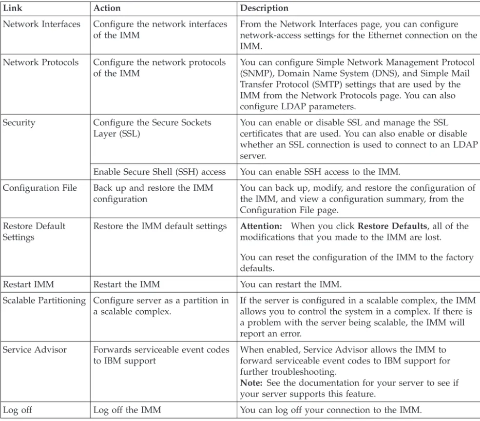
Link Action Description
Network Interfaces Configure the network interfaces of the IMM
From the Network Interfaces page, you can configure network-access settings for the Ethernet connection on the IMM.
Network Protocols Configure the network protocols of the IMM
You can configure Simple Network Management Protocol (SNMP), Domain Name System (DNS), and Simple Mail Transfer Protocol (SMTP) settings that are used by the IMM from the Network Protocols page. You can also configure LDAP parameters.
Security Configure the Secure Sockets Layer (SSL)
You can enable or disable SSL and manage the SSL certificates that are used. You can also enable or disable whether an SSL connection is used to connect to an LDAP server.
Enable Secure Shell (SSH) access You can enable SSH access to the IMM. Configuration File Back up and restore the IMM
configuration
You can back up, modify, and restore the configuration of the IMM, and view a configuration summary, from the Configuration File page.
Restore Default Settings
Restore the IMM default settings Attention: When you clickRestore Defaults, all of the modifications that you made to the IMM are lost. You can reset the configuration of the IMM to the factory defaults.
Restart IMM Restart the IMM You can restart the IMM. Scalable Partitioning Configure server as a partition in
a scalable complex.
If the server is configured in a scalable complex, the IMM allows you to control the system in a complex. If there is a problem with the server being scalable, the IMM will report an error.
Service Advisor Forwards serviceable event codes to IBM support
When enabled, Service Advisor allows the IMM to forward serviceable event codes to IBM support for further troubleshooting.
Note: See the documentation for your server to see if your server supports this feature.
Log off Log off the IMM You can log off your connection to the IMM.
You can click theView Configuration Summarylink, which is in the top-right corner on most pages, to quickly view the configuration of the IMM.
Chapter 3. Configuring the IMM
Use the links underIMM Controlin the navigation pane to configure the IMM. From the System Settings page, you can:
v Set server information v Set server timeouts v Set IMM date and time
v Enable or disable commands on the USB interface From the Login Profiles page, you can:
v Set login profiles to control access to the IMM
v Configure global login settings, such as the lockout period after unsuccessful login attempts
v Configure the account security level From the Alerts page, you can:
v Configure remote alert recipients v Set the number of remote alert attempts v Select the delay between alerts
v Select which alerts are sent and how they are forwarded From the Serial Port page, you can:
v Configure the baud rate of serial port 2 (COM2) for serial redirection v Specify the keystroke sequence that is used to switch between the serial
redirection and the command-line interface (CLI)
From the Port Assignments page, you can change the port numbers of IMM services.
From the Network Interfaces page, you can set up the Ethernet connection for the IMM.
From the Network Protocols page, you can configure: v SNMP setup
v DNS setup v Telnet protocol v SMTP setup v LDAP setup
v Service location protocol
From the Security page, you can install and configure the Secure Sockets Layer (SSL) settings.
From the Configuration File page, you can back up, modify, and restore the configuration of the IMM.
From the Restore Defaults page, you can reset the IMM configuration to the factory defaults.
From the Restart IMM page, you can restart the IMM.
Setting system information
To set the IMM system information, complete the following steps:
1. Log in to the IMM where you want to set the system information. For more information, see Chapter 2, “Opening and using the IMM web interface,” on page 11.
2. In the navigation pane, clickSystem Settings. A page similar to the one in the following illustration is displayed.
Note: The available fields in the System Settings page are determined by the accessed remote server.
3. In the Namefield in theIMM Informationarea, type the name of the IMM. Use theNamefield to specify a name for the IMM in this server. The name is included with e-mail and SNMP alert notifications to identify the source of the alert.
Note: Your IMM name (in theNamefield) and the IP host name of the IMM (in theHostnamefield on the Network Interfaces page) do not automatically share the same name because theNamefield is limited to 16 characters. The
Hostnamefield can contain up to 63 characters. To minimize confusion, set the
Namefield to the nonqualified portion of the IP host name. The nonqualified IP host name consists of up to the first period of a fully qualified IP host name. For example, for the fully qualified IP host name imm1.us.company.com, the nonqualified IP host name is imm1. For information about your host name, see “Configuring network interfaces” on page 36.
4. In the Contactfield, type the contact information. For example, you can specify the name and phone number of the person to contact if there is a problem with
Setting server timeouts
Note: Server timeouts require that the in-band USB interface (or LAN over USB) be enabled to allow commands. For more information about the enabling and disabling commands for the USB interface, see “Disabling the USB in-band interface” on page 23. For information regarding the installation of the required device drivers, see “Installing device drivers” on page 124.
To set the server timeout values, complete the following steps:
1. Log in to the IMM where you want to set the server timeouts. For more information, see Chapter 2, “Opening and using the IMM web interface,” on page 11.
2. In the navigation pane, clickSystem Settingsand scroll down to the Server Timeoutsarea.
You can set the IMM to respond automatically to the following events: v Halted operating system
v Failure to load operating system
3. Enable the server timeouts that correspond to the events that you want the IMM to respond to automatically.
OS watchdog
Use theOS watchdogfield to specify the number of minutes between checks of the operating system by the IMM. If the operating system fails to respond to one of these checks, the IMM generates an OS timeout alert and restarts the server. After the server is restarted, the OS watchdog is disabled until the operating system is shut down and the server is power cycled.
To set the OS watchdog value, select a time interval from the menu. To turn off this watchdog, select0.0from the menu. To capture
operating-system-failure screens, you must enable the watchdog in the
OS watchdogfield.
Loader watchdog
Use theLoader watchdogfield to specify the number of minutes that the IMM waits between the completion of POST and the starting of the operating system. If this interval is exceeded, the IMM generates a loader timeout alert and automatically restarts the server. After the server is restarted, the loader timeout is automatically disabled until the operating system is shut down and the server is power cycled (or until the operating system starts and the software is successfully loaded).
To set the loader timeout value, select the time limit that the IMM waits for the operating-system startup to be completed. To turn off this watchdog, select0.0from the menu.
Power off delay
Use thePower off delayfield to specify the number of minutes that the IMM waits for the operating system to shut down before it turns off the server power (if the power was not turned off by the operating system itself). If you set the power off delay, you can make sure that the operating system has enough time for an orderly shutdown before the server power is turned off. To determine the power off delay for your server, shut down your server and observe the amount of time it takes to shut down. Add a time buffer to that value and use the resulting number as your power off delay setting.
To set the power off delay value, select the desired time value from the menu. A value of X'0' means that the operating system, not the IMM, turns off the server power.
4. Scroll to the bottom of the page and clickSave.
Setting the IMM date and time
The IMM uses its own real-time clock to time stamp all events that are logged in the event log.
Note: The IMM date and time setting affects only the IMM clock, not the server clock. The IMM real-time clock and the server clock are separate, independent clocks and can be set to different times. To synchronize the IMM clock with the server clock, go to the Network Time Protocolarea of the page and set the NTP server host name or IP address to the same server host name or IP address that is used to set the server clock. See “Synchronizing clocks in a network” on page 23 for more information.
Alerts that are sent by e-mail and SNMP use the real-time clock setting to time stamp the alerts. The clock settings support Greenwich mean time (GMT) offsets and daylight saving time (DST) for added ease-of-use for administrators who are managing systems remotely over different time zones. You can remotely access the event log even if the server is turned off or disabled.
To verify the date and time settings of the IMM, complete the following steps: 1. Log in to the IMM where you want to set the IMM date and time values. For
more information, see Chapter 2, “Opening and using the IMM web interface,” on page 11.
2. In the navigation pane, clickSystem Settingsand scroll down to theIMM Date and Timearea, which shows the date and time when the webpage was generated.
3. To override the date and time settings and to enable daylight saving time (DST) and Greenwich mean time (GMT) offsets, clickSet IMM Date and Time. A page similar to the one in the following illustration is displayed.
4. In the Datefield, type the numbers of the current month, day, and year. 5. In the Timefield, type the numbers that correspond to the current hour,
minutes, and seconds in the applicable entry fields. The hour (hh) must be a number from 00 - 23 as represented on a 24-hour clock. The minutes (mm) and seconds (ss) must be numbers from 00 - 59.
6. In the GMT offsetfield, select the number that specifies the offset, in hours, from Greenwich mean time (GMT), corresponding to the time zone where the
Synchronizing clocks in a network
The Network Time Protocol (NTP) provides a way to synchronize clocks
throughout a computer network, enabling any NTP client to obtain the correct time from an NTP server.
The IMM NTP feature provides a way to synchronize the IMM real-time clock with the time that is provided by an NTP server. You can specify the NTP server that is to be used, specify the frequency with which the IMM is synchronized, enable or disable the NTP feature, and request immediate time synchronization.
The NTP feature does not provide the extended security and authentication that are provided through encryption algorithms in NTP Version 3 and NTP Version 4. The IMM NTP feature supports only the Simple Network Time Protocol (SNTP) without authentication.
To set up the IMM NTP feature settings, complete the following steps: 1. Log in to the IMM on which you want to synchronize the clocks in the
network. For more information, see Chapter 2, “Opening and using the IMM web interface,” on page 11.
2. In the navigation pane, clickSystem Settingsand scroll down to the IMM Date and Timearea.
3. ClickSet IMM Date and Time. A page similar to the one in the following illustration is displayed.
4. UnderNetwork Time Protocol (NTP), you can select from the following settings:
NTP auto-synchronization service
Use this selection to enable or disable automatic synchronization of the IMM clock with an NTP server.
NTP server host name or IP address
Use this field to specify the name of the NTP server to be used for clock synchronization.
NTP update frequency
Use this field to specify the approximate interval (in minutes) between synchronization requests. Enter a value between 3 - 1440 minutes.
Synchronize Clock Now
Click this button to request an immediate synchronization instead of waiting for the interval time to lapse.
5. ClickSave.
Disabling the USB in-band interface
Important: If you disable the USB in-band interface, you cannot perform an in-band update of the IMM firmware, server firmware, and DSA firmware by using the Linux or Windows flash utilities. If the USB in-band interface is disabled,
use the Firmware Update option on the IMM web interface to update the firmware. For more information, see “Updating firmware” on page 117.
If you disable the USB in-band interface, also disable the watchdog timeouts to prevent the server from restarting unexpectedly. For more information, see “Setting server timeouts” on page 21.
The USB in-band interface, or LAN over USB, is used for in-band communications to the IMM. To prevent any application that is running on the server from
requesting the IMM to perform tasks, you must disable the USB in-band interface. For more information about LAN over USB, see Chapter 6, “LAN over USB,” on page 123.
To disable the USB in-band interface, complete the following steps:
1. Log in to the IMM on which you want to disable the USB device driver interface. For more information, see Chapter 2, “Opening and using the IMM web interface,” on page 11.
2. In the navigation pane, clickSystem Settingsand scroll down to the
Miscellaneousarea. A page similar to the one in the following illustration is displayed.
3. To disable the USB in-band interface, selectDisabledfrom theAllow
commands on the USB interfacelist. Selecting this option does not affect the USB remote presence functions (for example, keyboard, mouse, and mass storage). When you disable the USB in-band interface, the in-band
systems-management applications such as the Advanced Settings Utility (ASU) and firmware update package utilities might not work.
Note: The ASU works with a disabled USB in-band interface if an IPMI device driver is installed.
If you try to use systems-management applications while the in-band interface is disabled, they might not work.
4. ClickSave.
To enable the USB device driver interface after it has been disabled, clear the Do not allow commands on USB interfacecheck box and clickSave.
Note:
1. The USB in-band interface is also called "LAN over USB" and is described in more detail in Chapter 6, “LAN over USB,” on page 123.
2. When you attempt a network installation of some Linux distributions, the installation might fail if the IMM USB in-band interface is enabled. For more
4. For information about the configuration of the LAN over USB interface, see “Configuring the LAN over USB interface manually” on page 124.
Creating a login profile
Use the Login Profiles table to view, configure, or change individual login profiles. Use the links in the Login ID column to configure individual login profiles. You can define up to 12 unique profiles. Each link in the Login ID column is labeled with the configured login ID of the associated profile.
Certain login profiles are shared with the IPMI user IDs, providing a single set of local user accounts (username/password) that work with all of the IMM user interfaces, including IPMI. Rules that pertain to these shared login profiles are described in the following list:
v IPMI user ID 1 is always the null user.
v IPMI user ID 2 maps to login ID 1, IPMI user ID 3 maps to login ID 2, and so on.
v The IMM default user is set toUSERIDand PASSW0RD(with a zero, not the letter O) for IPMI user ID 2 and login ID 1.
For example, if a user is added through IPMI commands, that user information is also available for authentication through the web, Telnet, SSH, and other interfaces. Conversely, if a user is added on the web or other interfaces, that user information is available for starting an IPMI session.
Because the user accounts are shared with IPMI, certain restrictions are imposed to provide a common ground between the interfaces that use these accounts. The following list describes IMM and IPMI login profile restrictions:
v IPMI allows a maximum of 64 user IDs. The IMM IPMI implementation allows only 12 user accounts.
v IPMI allows anonymous logins (null user name and null password), but the IMM does not.
v IPMI allows multiple user IDs with the same user names, but the IMM does not. v IPMI requests to change the user name from the current name to the same
current name return aninvalid parametercompletion code because the requested user name is already in use.
v The maximum IPMI password length for the IMM is 16 bytes.
v The following words are restricted and are not available for use as local IMM user names:
– immroot – nobody – ldap – lighttpd – sshd – daemon – immftp
To configure a login profile, complete the following steps:
1. Log in to the IMM where you want to create a login profile. For more information, see Chapter 2, “Opening and using the IMM web interface,” on page 11.
2. In the navigation pane, clickLogin Profiles.
Note: If you have not configured a profile, it does not appear in the Login Profiles table.
The Login Profiles page displays each login ID, the login access level, and the password expiration information, as shown in the following illustration.
Important: By default, the IMM is configured with one login profile that enables remote access using a login user ID ofUSERIDand a password of
PASSW0RD(the 0 is a zero, not the letter O). To avoid a potential security exposure, change this default login profile during the initial setup of the IMM. 3. ClickAdd User. An individual profile page similar to the one in the following
illustration is displayed.
4. In the Login IDfield, type the name of the profile. You can type a maximum of 16 characters in theLogin IDfield. Valid characters are uppercase and
Note: This password is used with the login ID to grant remote access to the IMM.
6. In the Confirm passwordfield, type the password again.
7. In the Authority Levelarea, select one of the following options to set the access rights for this login ID:
Supervisor
The user has no restrictions.
Read Only
The user has read-only access only and cannot perform actions such as file transfers, power and restart actions, or remote presence functions.
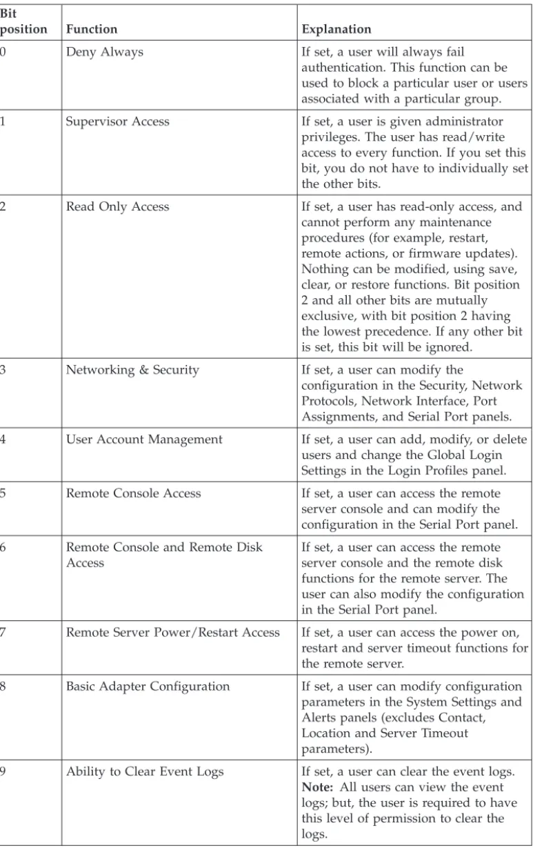
Custom
If you select the Custom option, you must select one or more of the following custom authority levels:
v User Account Management:A user can add, modify, or delete users and change the global login settings in the Login Profiles page. v Remote Console Access:A user can access the remote console. v Remote Console and Virtual Media Access:A user can access both
the remote console and the virtual media feature.
v Remote Server Power/Restart Access:A user can access the
power-on and restart functions for the remote server. These functions are available in the Power/Restart page.
v Ability to Clear Event Logs:A user can clear the event logs.
Everyone can look at the event logs, but this particular permission is required to clear the logs.
v Adapter Configuration - Basic: A user can modify configuration parameters in the System Settings and Alerts pages.
v Adapter Configuration - Networking & Security:A user can modify configuration parameters in the Security, Network Protocols,
Network Interface, Port Assignments, and Serial Port pages.
v Adapter Configuration - Advanced:A user has no restrictions when configuring the IMM. In addition, the user is said to have
administrative access to the IMM, meaning that the user can also perform the following advanced functions: firmware updates, PXE network boot, restore IMM factory defaults, modify and restore IMM configuration from a configuration file, and restart and reset the IMM.
When a user sets the authority level of an IMM login ID, the resulting IPMI privilege level of the corresponding IPMI User ID is set according to these priorities:
v If the user sets the IMM login ID authority level to Supervisor, the IPMI privilege level is set to Administrator.
v If the user sets the IMM login ID authority level to Read Only, the IPMI privilege level is set to User
v If the user sets the IMM login ID authority level to have any of the following types of access, the IPMI privilege level is set to
Administrator:
– User Account Management Access – Remote Console Access
– Remote Console and Remote Disk Access – Adapter Configuration - Networking & Security
– Adapter Configuration - Advanced
v If the user sets the IMM login ID authority level to have Remote Server Power/Restart Access or Ability to Clear Event Logs, the IPMI privilege level is set to Operator.
v If the user sets the IMM login ID authority level to have Adapter Configuration (Basic), the IPMI privilege level is set to User.
Note: To return the login profiles to the factory defaults, clickClear Login Profiles.
8. In the Configure SNMPv3 Userarea, select the check box if the user should have access to the IMM by using the SNMPv3 protocol. After you click the check box, an area of the page similar to the one in the following illustration appears.
Use following fields to configure the SNMPv3 settings for the user profile:
Authentication Protocol
Use this field to specify eitherHMAC-MD5orHMAC-SHAas the authentication protocol. These are hash algorithms used by the SNMPv3 security model for the authentication. The password for the Linux account will be used for authentication. If you chooseNone, authentication protocol is not used.
Privacy Protocol
Data transfer between the SNMP client and the agent can be protected using encryption. The supported methods areDESandAES. Privacy protocol is valid only if the authentication protocol is set to either HMAC-MD5 or HMAC-SHA.
Privacy Password
Use this field to specify the encryption password.
Confirm Privacy Password
Use this field to confirm the encryption password.
Access Type
Use this field to specify eitherGetorSetas the access type. SNMPv3 users with the access type Get can perform only query operations. With the access type Set, SNMPv3 users can both perform query operations and modify settings (for example, setting the password for an user).
Deleting a login profile
To delete a login profile, complete the following steps:
1. Log in to the IMM for which you want to create a login profile. For more information, see Chapter 2, “Opening and using the IMM web interface,” on page 11.
2. In the navigation pane, clickLogin Profiles. The Login Profiles page displays each login ID, the login access level, and the password expiration information. 3. Click the login profile that you want to delete. The Login Profile page for that
user is displayed
4. ClickClear Login Profile.
Configuring the global login settings
Complete the following steps to set conditions that apply to all login profiles for the IMM:
1. Log in to the IMM for which you want to set the global login settings. For more information, see Chapter 2, “Opening and using the IMM web interface,” on page 11.
2. In the navigation pane, clickLogin Profiles.
3. Scroll down to theGlobal Login Settingsarea. A page similar to the one in the following illustration is displayed.
4. In the User authentication methodfield, specify how users who are attempting to log in are authenticated. Select one of the following authentication methods: v Local only:Users are authenticated by a search of a table that is local to the
IMM. If there is no match on the user ID and password, access is denied. Users who are successfully authenticated are assigned the authority level that is configured in “Creating a login profile” on page 25.
v LDAP only:The IMM attempts to authenticate the user by using the LDAP server. Local user tables on the IMM are never searched with this
authentication method.
v Local first, then LDAP: Local authentication is attempted first. If local authentication fails, LDAP authentication is attempted.
v LDAP first, then Local: LDAP authentication is attempted first. If LDAP authentication fails, local authentication is attempted.
a. Only locally administered accounts are shared with the IPMI interface because IPMI does not support LDAP authentication.
b. Even if theUser authentication methodfield is set to LDAP only, users can log in to the IPMI interface by using the locally administered accounts.
5. In the Lockout period after 5 login failuresfield, specify how long, in minutes, the IMM prohibits remote login attempts if more than five sequential failures to log in remotely are detected. The lockout of one user does not prevent other users from logging in.
6. In the Web inactivity session timeoutfield, specify how long, in minutes, the IMM waits before it disconnects an inactive web session. SelectNo timeoutto disable this feature. SelectUser picks timeoutif the user will select the timeout period during the login process.
7. (Optional) In theAccount security levelarea, select a password security level. TheLegacy security settingsandHigh security settingsset the default values as indicated in the requirement list.
8. To customize the security setting, selectCustom security settingsto view and change the account security management configuration.
User login password required
Use this field to indicate whether a login ID with no password is allowed.
Number of previous passwords that cannot be used
Use this field to indicate the number of previous passwords that cannot be reused. Up to five previous passwords can be compared. Select0to allow the reuse of all previous passwords.
Maximum Password Age
Use this field to indicate the maximum password age that is allowed before the password must be changed. Values of 0 - 365 days are supported. Select0 to disable the password expiration checking. 9. ClickSave.
Configuring remote alert settings
You can configure remote alert recipients, the number of alert attempts, incidents that trigger remote alerts, and local alerts from the Alertslink on the navigation pane.
After you configure a remote alert recipient, the IMM sends an alert to that recipient through a network connection when any event selected from the
Monitored Alerts group occurs. The alert contains information about the nature of the event, the time and date of the event, and the name of the system that
generated the alert.
Note: If theSNMP AgentorSNMP Trapsfields are not set toEnabled, no SNMP traps are sent. For information about these fields, see “Configuring SNMP” on page 42.
Note: If you have not configured an alert recipient profile, the profile does not appear in the remote alert recipients list.
To configure a remote alert recipient, complete the following steps:
1. Log in to the IMM for which you want to configure remote alert settings. For more information, see Chapter 2, “Opening and using the IMM web interface,” on page 11.
2. In the navigation pane, clickAlerts. The Remote Alert Recipients page is displayed. You can see the notification method and alert status for each recipient, if they are set.
3. Click one of the remote alert recipient links or clickAdd Recipient. An individual recipient window similar to the one in the following illustration opens.
4. In the Statusfield, clickEnabledto activate the remote alert recipient.
5. In the Namefield, type the name of the recipient or other identifier. The name that you type appears as the link for the recipient on the Alerts page.
6. In the E-mail addressfield, enter the alert recipient's e-mail address. 7. Use the check box to include event logs with e-mail alerts.
8. In the Monitored Alertsfield, select the type of alerts that are sent to the alert recipient. The remote alerts are categorized by the following levels of severity:
Critical alerts
Critical alerts are generated for events that signal that a server component is no longer functioning.
Warning alerts
Warning alerts are generated for events that might progress to a critical level.