Microsoft
System
Center
David Ziembicki
Mitch Tulloch, Series Editor
Integrated Cloud
Platform
PUBLISHED BY Microsoft Press
A Division of Microsoft Corporation One Microsoft Way
Redmond, Washington 98052-6399
Copyright © 2014 Microsoft Corporation (All)
All rights reserved. No part of the contents of this book may be reproduced or transmitted in any form or by any means without the written permission of the publisher.
Library of Congress Control Number: 2014935076 ISBN: 978-0-7356-8314-3
Microsoft Press books are available through booksellers and distributors worldwide. If you need support related to this book, email Microsoft Press Book Support at [email protected]. Please tell us what you think of this book at http://www.microsoft.com/learning/booksurvey.
Microsoft and the trademarks listed at http://www.microsoft.com/about/legal/en/us/IntellectualProperty/ Trademarks/EN-US.aspx are trademarks of the Microsoft group of companies. All other marks are property of their respective owners.
The example companies, organizations, products, domain names, email addresses, logos, people, places, and events depicted herein are fictitious. No association with any real company, organization, product, domain name, email address, logo, person, place, or event is intended or should be inferred.
This book expresses the author’s views and opinions. The information contained in this book is provided without any express, statutory, or implied warranties. Neither the authors, Microsoft Corporation, nor its resellers, or distributors will be held liable for any damages caused or alleged to be caused either directly or indirectly by this book.
Acquisitions Editor: Anne Hamilton Developmental Editor: Karen Szall Project Editor: Karen Szall
Editorial Production: Diane Kohnen, S4Carlisle Publishing Services Copyeditor: Andrew Jones
Cover Illustration: Twist Creative • Seattle
iii
What do you think of this book? We want to hear from you!
Microsoft is interested in hearing your feedback so we can continually improve our books and learning resources for you. To participate in a brief online survey, please visit:
microsoft.com/learning/booksurvey
Contents
Introduction vii
Chapter 1 Hybrid cloud computing and the Microsoft Cloud OS 1
The Microsoft Cloud OS vision . . . .1
Hybrid cloud architectures . . . .2
Chapter 2 Private cloud
5
Software-defined storage . . . .5
Software-defined storage platform 7
Software-defined storage management 11
Additional storage capabilities 13
Cloud-integrated storage 14
Software-defined networking . . . .15
Software-defined network platform 15
Network architecture 19
Software-defined network management 20
Cloud-integrated networking 21
Software-defined compute . . . .22
Software-defined compute platform 22
Software-defined compute management 25
Software-defined management . . . .26
SQL Server 2012 26
System Center 2012 R2 Virtual Machine Manager 27
System Center 2012 R2 Operations Manager 28
System Center 2012 R2 Service Manager 29
System Center 2012 R2 Data Protection Manager 29
System Center 2012 R2 Orchestrator 29
System Center 2012 R2 App Controller 30
System Center 2012 R2 Windows Azure Pack 30
System Center 2012 R2 Configuration Manager 31
System Center 2012 R2 fabric management architecture 31
Chapter 3 Public cloud
35
Windows Azure overview . . . .35
Windows Azure compute services 36
Windows Azure storage and data services 37
Windows Azure network services 39
Windows Azure application services 39
Extending the datacenter fabric to Windows Azure . . . .41
Extending the datacenter network to Windows Azure 41
Extending datacenter storage to Windows Azure 44
Extending datacenter compute to Windows Azure 45
Extending datacenter fabric management to Windows Azure . . . .46
Self-Service 46
Updating and update management 47
Monitoring and alerting 48
Orchestration and automation 50
v Contents
Chapter 4 Service provider cloud
53
Cloud OS Network . . . .53
Extending the datacenter fabric to a service provider . . . .54
Extending the datacenter network to service providers 54
Extending datacenter storage to service providers 54
Extending datacenter compute to service providers 55
Extending datacenter fabric management to a service provider . . . .56
Service Provider Foundation 56
Windows Azure Pack 59
System Center 2012 R2 63
Hyper-V Replica 63
Conclusion . . . .65
What do you think of this book? We want to hear from you!
Microsoft is interested in hearing your feedback so we can continually improve our books and learning resources for you. To participate in a brief online survey, please visit:
vii
Introduction
M
icrosoft System Center: Integrated Cloud Platform is targeted toward IT executives and architects interested in the big picture of how Microsoft’s cloud strategy is delivered using Windows and Microsoft System Center. We provide an all-encompassing approach to understanding and architecting Windows Server 2012 R2, System Center 2012 R2, and Windows Azure based solutions for infrastructure as a service. The combination of Windows, System Center, and Windows Azure is a cloud-integrated platform, delivering what Microsoft calls the “Cloud OS,” which is a common platform spanning private cloud, public cloud (Windows Azure), and service provider clouds. This platform enables a single virtualization, identity, data, management, and development platform across all three cloud types.This book is organized by cloud type and we begin with a short overview of the Cloud OS strategy from Microsoft and a high-level hybrid cloud architecture that will be detailed throughout the book. Next we cover the design and deployment of private cloud solutions using Windows and System Center to deliver the software-defined datacenter where storage, network, compute, and management are all virtualized and delivered by the Microsoft platform. We cover some of the substantial cost savings that can be achieved using the Microsoft storage platform, the multi-tenancy enabled by our network virtualization platform, and the consolidation ratios that can be provided by Hyper-V’s scalability and high performance.
With a private cloud foundation in place, we next move to the public cloud and detail how to extend the private cloud datacenter (network, storage, compute, management) to Windows Azure while treating it as a seamless extension to your datacenter. Finally, the third cloud type, service provider clouds, are covered using the same approach—extending your datacenter to service providers. The end result is a robust hybrid cloud architecture where consumers of IT within an organization can choose the optimal location to host their virtual machines and services on any of the three cloud types based on which cloud makes the most sense for their workload.
Acknowledgments
This book summarizes the detailed architecture and design work captured in the Infrastructure as a Service (IaaS) reference architecture guides from Microsoft Services. The architectures represent years of lessons learned from our largest and
most complex customer implementations. Contributors to this body of knowledge include: Joel Yoker, Adam Fazio, Artem Pronichkin, Jeff Baker, Michael Lubanski, Robert Larson, Steve Chadly, Alex Lee, Yuri Diogenes, Carlos Mayol Berral, Ricardo Machado, Sacha Narinx, Thomas Ellermann, Aaron Lightle, Ray Maker, TJ Onishile, Ian Nelson, Shai Ofek, Anders Ravnholt, Ryan Sokolowski, Avery Spates, Andrew Weiss, Yuri Diogenes, Michel Luescher, Robert Heringa, Tiberiu Radu, Elena Kozylkova, and Jim Dial.
Errata, updates, & book support
We’ve made every effort to ensure the accuracy of this book and its companion content. You can access updates to this book—in the form of a list of submitted errata and their related corrections—at:
http://aka.ms/SCcloudplat/
If you discover an error that is not already listed, please submit it to us at the same page.
If you need additional support, email Microsoft Press Book Support at [email protected].
Please note that product support for Microsoft software and hardware is not offered through the previous addresses. For help with Microsoft software or hardware, go to http://support.microsoft.com.
We want to hear from you
At Microsoft Press, your satisfaction is our top priority, and your feedback our most valuable asset. Please tell us what you think of this book at:
http://aka.ms/tellpress
The survey is short, and we read every one of your comments and ideas. Thanks in advance for your input!
Stay in touch
Let’s keep the conversation going! We’re on Twitter: http://twitter.com/MicrosoftPress.
1
C H A P T E R 1
Hybrid cloud computing and
the Microsoft Cloud OS
A
number of key trends are driving the evolution of information technology (IT) today. New applications requiring global scale, social integration, and mobile capability are critical in many industries. The proliferation of devices such as smart phones and tablets is driving the need for applications and services delivery to nearly everywhere on the globe. The explosion of data and the insight that can be gained from the exponential growth in data is generating demand for enormous storage and analysis capability. These trends have triggered significant changes to how IT must be delivered, resulting in the evolution of cloud computing.Cloud computing is delivered in many forms such as private cloud in an organization’s datacenter, public cloud in a provider such as Microsoft’s datacenter, or a multitude of service provider clouds from a range of different organizations. Each provides a different set of features, capabilities, cost points, and service level agreements (SLA).
Within this environment, organizations have a wide range of options for their cloud computing needs and an increasing challenge of how to manage a distributed, cloud-based infrastructure as well as their various applications and services. As a leading provider of on-premises software solutions and one of the largest global cloud providers, Microsoft has created a single integrated cloud platform to meet customer’s needs: the Cloud OS.
The Microsoft Cloud OS vision
The Microsoft Cloud OS strategy can be summarized by the following quote from the white paper “Unified Management for the Cloud OS: System Center 2012 R2” published in October 2013:
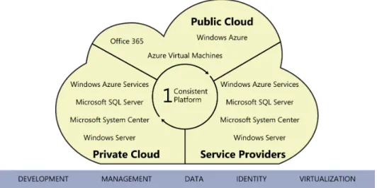
“The Microsoft vision for a new era of IT provides one consistent platform for infrastructure, applications, and data: the Cloud OS. The Cloud OS spans your datacenter environments, service provider datacenters, and Windows Azure, enabling you to easily and cost-effectively cloud optimize your business.”
This strategy is unique in the industry as Microsoft is the only global provider of leading on-premises software for private cloud, large scale public cloud with Windows Azure, and a global service provider ecosystem.
The Cloud OS strategy provides a common identity, virtualization, management, development, and data platform across private cloud, public cloud, and service-provider cloud as illustrated in Figure 1-1.
FIGURE 1-1 The Microsoft Cloud OS vision.
The various combinations of private, public, and service provider clouds are commonly referred to as hybrid cloud architectures. The ability to both provide the various types of cloud infrastructure as well as the ability to manage resources across all of them requires an integrated cloud platform such as Microsoft’s Cloud OS comprised of Windows Server, Windows Azure, and System Center.
Hybrid cloud architectures
The key attribute of the Cloud OS vision is hybrid cloud architecture, in which customers have the option of leveraging on-premises infrastructure, Windows Azure, or Microsoft hosting-partner infrastructure. The customer IT organization will be both a consumer and provider of services, enabling workload and application development teams to make sourcing selections for services from all three of the possible infrastructures or create solutions that span them.
Starting from the bottom, the diagram in Figure 1-2 illustrates the cloud infrastructure level (public, private, and hosted clouds), the cloud service catalog space, and examples of application scenarios and service-sourcing selections (for example, a workload team determining if it will use virtual machines that are provisioned on-premises, in
Hybrid cloud architectures CHAPTER 1 3 Windows Azure, or in a Microsoft hosting partner.) The Cloud OS strategy provides a common
identity, virtualization, management, development, and data platform across private cloud, public cloud, and service provider cloud.
FIGURE 1-2 Hybrid cloud architecture details.
The benefits of this approach are that virtual machines, applications, and services can be hosted on the cloud that makes the most sense for each workload in terms of cost, capability, or SLA. Additionally, the Cloud OS enables “VM Mobility” as all three components (private, public/Azure, service provider) utilize the same underlying Windows Server 2012 R2 and Hyper-V infrastructure meaning that virtual machines can be moved to any of the cloud types without having to convert or modify them. The Cloud OS is an integrated cloud platform where System Center 2012 R2 is able to manage the private cloud as well as virtual machines, applications, and services hosted in Windows Azure or service provider clouds.
In the next several chapters we will outline how to use the Cloud OS to build a
software-defined datacenter and private cloud with Windows Server, Hyper-V, and System Center as well as consume Windows Azure and service provider clouds by extending your datacenter and System Center management platform to those clouds. The end result will be a hybrid cloud architecture that enables applications, workloads, and services to be hosted on the cloud that makes the most sense for them while providing an integrated management capability across the hybrid cloud.
5
C H A P T E R 2
Private cloud
I
n this chapter we’ll begin the design of the private cloud portion of the hybrid cloud architecture. The sample design we’ll build over the next several chapters is an overview of the detailed architecture provided in the following guides on Microsoft TechNet:■
■ “Infrastructure as a Service Product Line Architecture - Fabric Architecture Guide” found at http://aka.ms/iaasfabricarchitecture
■
■ “Infrastructure as a Service Product Line Architecture - Fabric Management Guide” found at http://aka.ms/iaasfabricmanagement
■
■ “Infrastructure as a Service Product Line Architecture - Deployment Guide” found at http://aka.ms/iaasdeployment
Software-defined storage
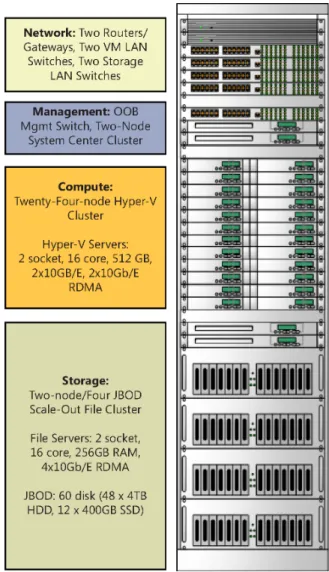
For the purposes of this book, we will build a private cloud architecture consisting of a storage scale-unit, a compute scale-unit, and a network scale-unit which establish a single-rack configuration supporting over 1,000 virtual machines, over half a petabyte of storage, over one million IOPS capacity, and over 40 Gb/s to/from the external LAN. The scale-unit architecture can be expanded with additional racks. The sample architecture is illustrated in Figure 2-1 and in Table 2-1. While this book describes how to build such an architecture, several of the Microsoft OEM partners deliver turn-key solutions using this design approach.
FIGURE 2-1 The sample private cloud architecture used for this book.
TABLE 2-1 Details of Sample Private Cloud Architecture Used for this Book Functionality Details
Network Two Routers/Gateways, Two VM LAN Switches, Two Storage LAN Switches Management OOB Mgmt Switch, Two-Node System Center Cluster
Compute Twenty-Four-node Hyper-V Cluster
Hyper-V Servers: 2 socket, 16 core, 512 GB, 2x10GB/E, 2x10Gb/E RDMA Storage Two-node / Four JBOD Scale-Out File Server custer
File Servers: 2 socket, 16 core, 256GB RAM, 4x10Gb/E RDMA JBOD: 60 disk (48 x 4TB HDD, 12 x 400Gb SSD)
Software-defined storage CHAPTER 2 7 We’ll start with a new approach to enterprise storage called software-defined storage or
virtual SAN. In most enterprise datacenters today, storage infrastructure and management is one of the highest cost areas of IT. This is in stark contrast to large cloud providers such as Microsoft which have enormous storage infrastructures which dwarf most enterprises but are far more cost efficient. How is this possible? Through the use of commodity hardware and advanced software where all of the storage “intelligence” is provided not by custom hardware but by software.
Software-defined storage platform
With Windows Server 2012 R2, Microsoft has added substantial software-defined storage capabilities to the platform, enabling customers to establish advanced storage infrastructures at substantially lower costs than traditional hardware-based SAN solutions. Figure 2-2 illustrates the architecture of a software-defined storage solution using Windows Server 2012 R2.
FIGURE 2-2 A sample architecture for a software-defined storage solution based on Windows Server 2012 R2.
While this architecture provides many of the same capabilities as a SAN, it is comprised of the following commodity hardware components:
■
■ SAS disks SAS disks provide high performance in throughput and, more importantly, low latency. SAS drives typically have a rotational speed of 10,000 or 15,000 RPM with an average latency of 2 ms to 3 ms and 6 Gbps interfaces. There are also SAS SSDs supporting substantially higher IOPS than spinning disks. SAS disks can support dual interface ports which is required for using clustered storage spaces. The SCSI Trade Association has a range of information about SAS. SAS disks are very common and are available from a wide range of vendors and price points.
■
■ SAS JBOD SAS JBOD (“just a bunch of disks”) refers to the disk trays or enclosures where SAS disks are housed. The difference between JBOD and an array or SAN is that a JBOD tray does not have any RAID, storage management, or other intelligence built-in, it is simply a physical component providing SAS connectivity between servers and multiple disks. SAS JBOD typically support 24 or 60 SAS disks in a single enclosure with two to four SAS ports for server connectivity.
■
■ Windows Server 2012 Scale-out File Servers In a traditional SAN architecture, most of the functionality and intelligence is provided by the SAN controllers. These are proprietary hardware and software solutions from SAN vendors. In the Microsoft software-defined storage architecture, this functionality is provided by standard server hardware running Windows Server 2012 R2. Just as a SAN controller provides disk resiliency through RAID and advanced features such as tiering and quality of service, the Windows Server 2012 R2 file server infrastructure provides the same capabilities through software combined with commodity server hardware.
With the physical infrastructure in place, the software-defined capabilities of Windows Server 2012 R2 can then be utilized. The Windows Server 2012 R2 platform enables a range of storage virtualization capabilities called Storage Spaces. Storage Spaces enables cost-efficient, highly available, scalable, and flexible storage solutions. Storage Spaces delivers advanced storage virtualization capabilities for single server and scalable multinode cluster deployments.
With Storage Spaces. the Windows storage stack has been enhanced to incorporate two new abstractions:
■
■ Storage pools A collection of physical disks that enable you to aggregate disks,
expand capacity in a flexible manner, and delegate administration.
■
■ Storage spaces Virtual disks created from free space in a storage pool. Storage
spaces have such attributes as resiliency level, storage tiers, fixed provisioning, and precise administrative control.
Storage Spaces is manageable through the Windows Storage Management API in Windows Management Instrumentation (WMI), Windows PowerShell, and through the File and Storage Services role in Server Manager. Storage Spaces is completely integrated with failover clustering for high availability, and it is integrated with CSV for scale-out deployments. In addition, System Center 2012 R2 enables full deployment and management of the software-defined storage architecture using Virtual Machine Manager which will be covered in detail later in this chapter.
While the focus of this chapter is the Microsoft software-defined storage architecture using commodity components to achieve extremely cost efficient and high performance virtual machine storage, it is very important to understand that the new Microsoft storage platform is multiprotocol and able to support and enhance heterogeneous storage
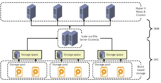
environments. Windows File server clusters can front-end both Fibre Channel and iSCSI-based SAN environments for customers with existing investments. Additionally, file server clusters based on Windows Server 2012 R2 can present three types of storage: SMB 3.0 file shares, iSCSI targets, and NFS shares as illustrated in Figure 2-3.
Software-defined storage CHAPTER 2 9 FIGURE 2-3 Supported storage for file server clusters based on Windows Server 2012 R2.
This flexibility allows for a wide range of storage hardware to be utilized and adds significant performance and availability features to each of the supported storage features included in Windows Server 2012 R2, such as:
■
■ Chkdsk enhancements ■
■ CSV v2 ■
■ Data deduplication ■
■ Improved NTFS availability ■
■ iSCSI target improvements ■
■ Live storage migration ■
■ NFS improvements ■
■ ODX ■ ■ QoS
■ ■ ReFS
■
■ SMB application support ■
■ SMB Direct ■
■ SMB multichannel ■
■ SMB scale-out ■
■
■ SMB VSS for remote file shares ■
■ Storage spaces ■
■ Storage Tiering ■
■ Thin and trim provisioning ■
■ Virtual fibre channel ■
■ Write Back Cache
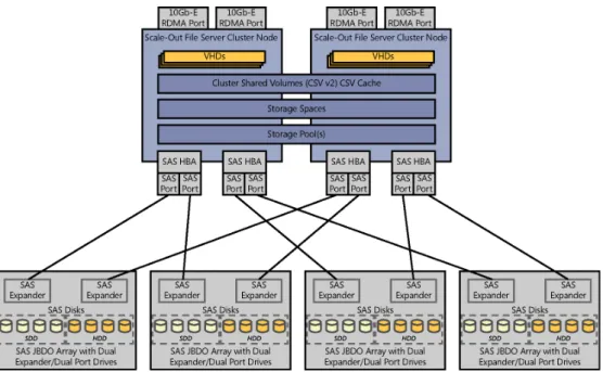
An example of the design of the software-defined storage architecture is illustrated in Figure 2-4. Note the SAS disk, JBOD, and Windows file server components. This design details a highlight available architecture using a Scale-out File Server cluster and clustered storage spaces.
FIGURE 2-4 A design for a software-defined storage architecture.
The above design can support a significant number of virtual machines and IOPS using only two file servers and four JBODs. The architecture is a scale-out design meaning additional servers and JBODs can be added in order to support a larger number of virtual machines or applications.
Key factors in sizing and designing the software-defined storage architecture include the number of virtual machines to be hosted, storage capacity, IOPS required, resiliency required, etc. Those requirements then impact the number and types of disk, the ratios of HDD to SSD, how many SAS and Ethernet/RDMA connections per file server, and so on.
Software-defined storage CHAPTER 2 11 The above design approach provides a continuously available infrastructure meaning if
you have two or more file servers, three or more JBODs, and redundant network and storage connectivity, any component in the architecture can fail with no downtime of the storage or virtual machines.
While a detailed design is beyond the scope of this book, significant detail is provided in the “Infrastructure as a Service Product Line Architecture” document referred to at the beginning of this chapter. In that document we provide a detailed reference architecture for the software-defined storage approach (as well as designs for non-converged and converged storage architectures).
Software-defined storage management
With a general understanding of the software-defined storage architecture, it becomes clear that there is a significant amount of configuration possibilities as each layer of the architecture such as hardware, operating system, failover clustering, storage spaces, and file server role have a multitude of settings and options available. While all of these are configurable via Windows PowerShell to enable automation, System Center 2012 R2 Virtual Machine Manager (VMM) is able to automate the deployment and management of the software-defined storage architecture.
Using VMM to deploy the software-defined storage architecture begins with ensuring the VMM fabric (library, host groups, network, and storage discovery) is configured. This ensures basic prerequisites such as operating system images and other environment configuration settings are specified. The process for using VMM to deploy Scale-out File Server cluster is documented in detail on Microsoft TechNet (see http://technet.microsoft.com/en-us/library/ gg610634.aspx) and the following steps are summarized from that article:
1. Perform initial configuration of the physical computers. This includes configuring the basic input/output system (BIOS) to support virtualization, setting the BIOS boot order to boot from a Pre-Boot Execution Environment (PXE)-enabled network adapter as the first device, and configuring the logon credentials and IP address settings for the baseboard management controller on each computer.
2. Create Domain Name System (DNS) entries and Active Directory computer accounts for the computer names that will be provisioned, and allow time for DNS replication to occur. This step is not required, but it is strongly recommended in an environment where you have multiple DNS servers, where DNS replication may take some time. 3. Prepare the PXE server environment, and add the PXE server to VMM management. 4. Add the required resources to the VMM library. These resources include a generalized
virtual hard disk with an appropriate operating system that will be used as the base image, and optional driver files to add to the operating system during installation.
5. In the library, create one or more host profiles, or as of Virtual Machine Manager 2012 R2 (VMM), physical computer profile. These profiles include configuration settings, such as the location of the operating system image, and hardware and operating system configuration settings.
6. To create a Hyper-V host, run the Add Resources Wizard to discover the physical computers, to configure settings such as the host group and the host or physical computer profile to use, to configure custom deployment settings, and to start the operating system and Hyper-V deployment.
7. To create a Scale-out File Server cluster (as of System Center 2012 R2 Virtual Machine Manager only), run the Create Clustered File Server Wizard to discover the physical computers, to configure settings such as the cluster name, provisioning type, and discovery scope, and to start the Scale-out File Server cluster deployment.
8. During deployment, the VMM management server restarts the physical computers by issuing “Power Off” and “Power On” commands to the BMC through out-of-band management. When the physical computers restart, the PXE server responds to the boot requests from the physical computers.
9. The physical computers boot from a customized Windows Preinstallation Environment (Windows PE) image on the PXE server. The Windows PE agent prepares the computer, configures the hardware when it is necessary, downloads the operating system image (.vhd or .vhdx file) together with any specified driver files from the library, and applies the drivers to the operating system image.
10. Roles are then enabled as follows: ■
■ For Hyper-V hosts, the Hyper-V role is enabled. ■
■ For Scale-out File Servers (as of VMM 2012 R2 only) the Failover Cluster feature and File Server role are enabled. Then, after the cluster is created, the Scale-out File Server role is enabled in the cluster.
11. The computer is then restarted.
To deploy the basic software-defined storage scale unit (the two-node scale-out file cluster illustrated previously), the above procedure would be utilized to configure two bare-metal servers with Windows Server 2012 R2. Those two servers would then be configured by VMM to form a Scale-out File Server cluster using the following steps:
1. Enable the file server role on the computers. 2. Enable the Scale-out File Server role on the cluster.
3. Add the provisioned computers as a Scale-out File Server cluster under VMM management.
The above procedures can also be performed in one process using the Create Clustered File Server Wizard in VMM.
With the above process completed, a new two-node Scale-out File Server cluster is now part of the fabric defined and managed by VMM. VMM will discover all of the physical
Software-defined storage CHAPTER 2 13 storage (SAS JBOD, disks, and so on) attached to the cluster and be able to manage and
configure that as well. The process consists of creating a storage pool using some or all of the physical disks available to the cluster. While simple, this part of the setup is critical as your choices of which disks (HDD, SSD, or combination of both) determine the capacity and performance characteristics of the pool you are about to configure.
After the storage pool(s) have been configured, the next step is to create storage spaces, cluster shared volumes, and file shares to present the storage. This also is accomplished in VMM using simple wizards. The Create File Share Wizard will ask you which storage pool you would like to create the share on then it will ask for a critical piece of information, the resilience and redundancy options for the storage space that will be created on the storage pool. The options are:
■
■ Parity Allows you to select Single or Dual. ■
■ Mirror Allows you to select Two-way or Three-way.
These settings determine the resiliency to disk failure that the storage space can provide. Parity provides better capacity utilization but is not as high performance as mirroring. Dual parity or Three-way mirroring provide higher resiliency as more disks can fail without losing data than Single parity or Two-way mirroring.
With the deployment of SMB 3.0 file shares on the scale-out file cluster, the architecture is now able to present high speed and high availability storage. From bare-metal servers and JBOD in the rack, VMM is able to deploy and configure the complete storage architecture. Advanced features such as tiering, QoS, RDMA, and many others are available. At a cost point far lower than most SANs, this architecture provides an excellent starting point for a virtualized private cloud architecture.
Additional storage capabilities
While we have discussed in some detail software-defined storage and management, System Center also provides robust support for managing SAN and converged storage infrastructures. Many organizations have significant investments in storage that they want to continue to leverage and VMM provides the same management capabilities for physical storage infrastructures as for virtual or software-defined storage infrastructures.
VMM has been enhanced to support managing disparate storage architectures including Fibre Channel and iSCSI SAN. VMM can add and discover external storage arrays that are managed by Storage Management Initiative—Specification (SMI-S) or Store Management Provider (SMP) providers. VMM can also manage virtual Fibre Channel so that an existing Fibre Channel SAN can be utilized by guest virtual machines. Similarly to the SMB 3.0 software-defined storage approach, a significant amount of storage integration and management can be performed in software with VMM in concert with physical storage infrastructure.
Cloud-integrated storage
In addition to on-premises, Windows Server 2012 R2 storage solutions, the Microsoft storage platform also includes cloud-integrated storage using StorSimple.
StorSimple cloud-integrated storage (CiS) provides primary storage, backup, archive, and disaster recovery. Combined with Windows Azure, this hybrid cloud storage solution optimizes total storage costs and data protection for enterprises.
Cloud-integrated storage enables a seamless continuum of storage, comprised of multiple tiers such as local SSD, local HDD, and remote Windows Azure storage with the ability to place data in the most optimal location based on usage and cost. Figure 2-5 illustrates extending the previously described storage architecture comprised of Windows Server 2012 R2 and SAS JBOD storage to include the StorSimple appliance and connectivity to Windows Azure storage for a complete cloud-integrated storage solution with multiple storage tiers.
FIGURE 2-5 A storage architecture that includes the StorSimple appliance and connectivity to Windows Azure storage.
Software-defined networking CHAPTER 2 15 A full discussion of hybrid storage is beyond the scope of this book but is the focus
of another Microsoft Press e-book titled Rethinking Enterprise Storage: A Hybrid Cloud Model (ISBN 9780735679603), by Marc Farley http://blogs.msdn.com/b/microsoft_press/ archive/2013/07/26/free-ebook-rethinking-enterprise-storage-a-hybrid-cloud-model.aspx.
Software-defined networking
The concepts of software-defined networking are similar to those of software-defined storage in that the software provides the majority of the intelligence and functionality of the network infrastructure. This can also be described as separating the control plane (how network traffic is routed/processed) from the data plane (the packets and data that flow and traverse the network) and implementing the control plane in software as opposed to hardware (for example, virtual routers instead of physical routers). The benefits are the same as with storage such as increased flexibility and agility in being able to re-configure the network architecture as needs change without having to replace hardware.
Software-defined network platform
As with storage, Windows Server 2012 R2 and System Center 2012 R2 contain large investments in software-defined networking capability. Many of the design requirements were driven by the needs of large enterprises and service providers architecting large scale, multitenant infrastructure as a service (IaaS) solutions. A number of different platform and management capabilities are required to truly deliver a software-defined networking solution.
Hyper-V NIC teaming
From Windows Server 2012 onward, network interface card (NIC) teaming is a built-in feature of the operating system with a simple and easy to use interface for rapidly configuring teaming for highly available network connectivity to hosts and virtual machines. NIC teaming includes several modes and options which can be configured for different design scenarios. Windows Server NIC teaming is the foundation of a software-defined network infrastructure as it ensures that all higher-level networking capabilities are built on a highly available foundation with hosts using two or more network adapters. NIC teaming enables both network high availability as well as bandwidth aggregation.
Hyper-V Virtual Switch
As described on Microsoft TechNet, the Hyper-V Virtual Switch is a software-based layer-2 network switch that is available in Hyper-V Manager when you install the Hyper-V server role. The Hyper-V Virtual Switch includes programmatically managed and extensible capabilities to connect virtual machines to both virtual networks and the physical network. In addition, Hyper-V Virtual Switch provides policy enforcement for security, isolation, and service levels.
With built-in support for Network Device Interface Specification (NDIS) filter drivers and Windows Filtering Platform (WFP) callout drivers, the Hyper-V Virtual Switch enables independent software vendors (ISVs) to create extensible plug-ins (known as Virtual Switch Extensions) that can provide enhanced networking and security capabilities. Virtual Switch Extensions that you add to the Hyper-V Virtual Switch are listed in the Virtual Switch Manager feature of Hyper-V Manager.
Virtual Switch extension types include capturing, filtering, and forwarding extensions which correspond to the types of actions the extensions can take. For example, a capture extension can capture and examine traffic but cannot change it. A filtering extension can make policy decisions such as evaluating firewall rules and determine whether to allow the traffic to pass through the switch or not. Finally, forwarding extensions can forward traffic flow information to an external system such as a virtual appliance for network policy enforcement. An example of a full featured forwarding extension is the Cisco Nexus 1000v solution for Hyper-V.
A diagram of the Hyper-V Virtual Switch architecture, derived from a diagram on Microsoft MSDN (http://msdn.microsoft.com/en-us/library/windows/hardware/hh582268(v=vs.85).aspx), is illustrated in Figure 2-6.
The Hyper-V Virtual Switch is the key enabling feature for software-defined networking as it exists between the Hyper-V host’s physical network connectivity and all of the host’s virtual machines. Having a software layer at that point enables the features listed above as well as many others. The extensible design of the switch allows enhancements by Microsoft or partners to add new capabilities.
The features of the Hyper-V Virtual Switch include: ■
■ ARP/ND Poisoning (spoofing) protection Provides protection against a malicious
VM using Address Resolution Protocol (ARP) spoofing to steal IP addresses from other VMs. Provides protection against attacks that can be launched for IPv6 using Neighbor Discovery (ND) spoofing.
■
■ DHCP Guard protection Protects against a malicious VM representing itself as a
Dynamic Host Configuration Protocol (DHCP) server for man-in-the-middle attacks.
■
■ Port ACLs Provides traffic filtering based on Media Access Control (MAC) or Internet Protocol (IP) addresses/ranges, which enables you to set up virtual network isolation. ■
■ Trunk mode to a VM Enables administrators to set up a specific VM as a virtual
appliance, and then direct traffic from various VLANs to that VM.
■
■ Network traffic monitoring Enables administrators to review traffic that is traversing the network switch.
■
■ Isolated (private) VLAN Enables administrators to segregate traffic on multiple VLANs, to more easily establish isolated tenant communities.
■
■ Bandwidth limit and burst support Bandwidth minimum guarantees amount of bandwidth reserved. Bandwidth maximum caps the amount of bandwidth a VM can consume.
Software-defined networking CHAPTER 2 17
■
■ ECN marking support Explicit Congestion Notification (ECN) marking—also known as Data Center TCP (DCTCP)—enables the physical switch and operating system to regulate traffic flow such that the buffer resources of the switch are not flooded, which results in increased traffic throughput.
■
■ Diagnostics Diagnostics allow easy tracing and monitoring of events and packets through the virtual switch.
FIGURE 2-6 An example of the Hyper-V Virtual Switch architecture.
The above features can be combined with NIC teaming to enable highly available network access to virtual machines. The security features can be used to ensure that virtual machines that may become compromised are not able to impact other virtual machines through ARP spoofing or DHCP man-in-the-middle attacks. Port ACLs open a wide range of scenarios for protecting virtual machines through access control lists on the virtual switch.
Several of the Hyper-V Virtual Switch features establish the foundation for secure, multitenant environments. Network quality of service (QoS) is enabled through bandwidth limiting and burst support to prevent virtual machines from becoming “noisy neighbors” or
consuming too much host capacity. Private Virtual LANs (PVLANs) enable isolation of virtual machine network traffic.
Hyper-V Network Virtualization
Hyper-V Network Virtualization provides the concept of a virtual network that is independent of the underlying physical network. With this concept of virtual networks, which are
composed of one or more virtual subnets, the exact physical location of an IP subnet is decoupled from the virtual network topology. As a result, customers can easily move their subnets to the cloud while preserving their existing IP addresses and topology in the cloud, so that existing services continue to work unaware of the physical location of the subnets. A high-level diagram of a virtualized network environment is illustrated in Figure 2-7.
FIGURE 2-7 An example of Hyper-V Network Virtualization.
Hyper-V Network Virtualization in Windows Server 2012 R2 provides policy-based, software-controlled network virtualization that reduces the management overhead. In addition, it provides cloud hosting providers with better flexibility and scalability for managing virtual machines to achieve higher resource utilization.
The details of Hyper-V Network Virtualization are fairly complex and beyond the scope of this book. Several key points for consideration are the separation and isolation of the virtual networks created per tenant, the ability for tenants to “bring their own IP address and subnets,” and the separation of all of the tenant/customer virtual networks from the provider or datacenter physical network infrastructure. The primary value is that changes to the virtual networks, such as creation/modification/deletion, do not require changes to the underlying physical network infrastructure. This capability is in contrast to VLAN-based approaches which often do require changes to physical network infrastructure configuration of switch ports.
Software-defined networking CHAPTER 2 19 Another key consideration with network virtualization is that traffic encapsulation using
Network Virtualization for Generic Routing Encapsulation (NVGRE) is the mechanism utilized for virtualizing IP addresses and subnets. The customer or tenant network traffic (from the virtual networks) is encapsulated inside the provider address space packets. This virtualization is what enables the separation between the tenants and the provider. All of the network virtualization functionality works between all Hyper-V hosts in the provider environment, however a key question is how this network virtualization works between Hyper-V hosts and non-virtualized servers or networks outside of the provider datacenter. In those scenarios, the functionality of a network virtualization gateway. The gateway, either a physical or virtual appliance, sits at the edge of the Hyper-V Network Virtualization infrastructure and outside networks, to de-capsulate outbound virtual network traffic and encapsulate inbound traffic to virtual networks.
Hyper-V Network Virtualization builds on and works with the NIC Teaming and Virtual Switch capabilities described previously to enable the complete software-defined network infrastructure required for today’s large scale, multitenant datacenters. These foundational technologies exist in Windows Server 2012 R2, but to enable true software-defined
networking, a centralized management capability spanning all participating Hyper-V servers is required.
Network architecture
In the design example illustrated in Figure 2-1 and detailed in Table 2-1, several different physical networks were described. The first is a physical management network for accessing the baseboard management controllers on all of the physical servers as well as management ports on any of the network and/or storage devices. This connectivity is provided by a dedicated physical network switch in the single rack design.
The next two networks are the storage and LAN networks. These can share the same physical infrastructure but in the sample design we illustrate a dedicated pair of switches for the storage network which would host all of the SMB storage traffic between the Hyper-V hosts and the Scale-out File Server clusters.
The second pair of dedicate switches host the LAN traffic between all of the physical servers and virtual machines. These switches can be connected to any other datacenter networks that will be utilizing Hyper-V Network Virtualization.
For connectivity to datacenter networks or external networks not utilizing network virtualization, the Hyper-V Network Virtualization Gateways are utilized. These are illustrated as physical servers or appliances however they can also be deployed as virtual machines by System Center VMM so the two single-rack unit appliances could be dedicated Hyper-V hosts running one or more network virtualization gateways.
You should plan carefully to ensure that there is balance between the storage, LAN, and external network infrastructures. You want to avoid bottlenecks between the external to LAN and the hosted virtual machines and between the virtual machines and the file server-based storage infrastructure. An additional consideration arises in large scale scenarios where
more than one rack scale-unit will be deployed to ensure that there is adequate bandwidth between the physical networks spanning racks.
Software-defined network management
All of the technologies discussed so far in Windows Server 2012 R2 are the basis for a software-defined network and delivered through the Hyper-V hosts in the overall IaaS architecture. System Center 2012 R2 VMM provides the centralized management solution for the IaaS fabric. Similar to software-defined storage where VMM provides deployment and management of storage infrastructure, VMM also provides the management capability for software-defined networking. VMM is used to manage and configure the provider network and establish the tenant virtual networks.
VMM utilizes a relatively complex but very flexible set of abstractions to represent all of the software-defined network elements and constructs. The primary construct is a “logical network” which consists of child objects such as “network sites,” “IP subnet/VLANs,” and “IP Address Pools.” These constructs enable modeling of complex network infrastructures. Logical networks can be assigned to Hyper-V hosts or host groups by VMM so that those hosts and virtual machines are configured to utilize those logical networks. These constructs are utilized to configure the fabric or provider network infrastructure in a VMM fabric.
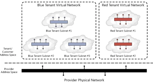
When utilizing Hyper-V Network Virtualization, VMM is also utilized to configure all of the available virtual networks for each tenant as well as their component subnets and IP address pools. Figure 2-8, adapted from Microsoft TechNet (http://technet.microsoft.com/en-us/ library/jj983727.aspx), illustrates the relationships between these objects.
FIGURE 2-8 An example of the VMM networking object model.
The diagram shows the provider address space (the physical infrastructure managed by VMM) and one VM network, which is a tenant or customer address space defined via Hyper-V Network Virtualization. For simplicity only one VM network is shown, in reality there may be
Software-defined networking CHAPTER 2 21 hundreds or more VM networks in scenarios such as a service provider with multiple, isolated
VM networks for each of their customers.
In addition to the capabilities discussed so far, VMM is also able to integrate with and manage physical network infrastructure components such as Top of Rack (ToR) switches. VMM can integrate with network equipment that supports Open Management Infrastructure (OMI). In this case, VMM can configure things such as switch port types, trunking, and so on.
A final software-defined networking capability provided by VMM is the automatic deployment and configuration of Hyper-V Network Virtualization gateways. VMM can deploy both stand-alone and highly available pairs of virtual machines acting as network virtualization gateways. This functionality is provided using VMM service templates.
When utilized together, all of the VMM network management capabilities deliver a complete software-defined networking infrastructure, such as the physical fabric network (provider), virtual networks (tenant/customer), and network virtualization gateways that can all be provisioned and managed by VMM.
Cloud-integrated networking
As discussed in Chapter 1, “Hybrid cloud computing and the Microsoft Cloud OS,” the Cloud OS strategy encompasses more than just the private cloud on-premises datacenter by addressing both the public cloud (Windows Azure) and service provider cloud. Cloud-integrated networking refers to extending the on-premises datacenter network to both the public cloud and service providers.
Utilizing a combination of Hyper-V Network Virtualization, network virtualization gateways, and site-to-site VPN between both the private cloud datacenter and the service provider datacenter, an organization can establish a software-defined network that spans both infrastructures. The service provider must enable such functionality using Hyper-V and related components, which is one of the reasons for choosing service providers such as those in the Microsoft Cloud OS Network who utilize the Microsoft platform as the basis of their hosting infrastructure.
In addition to service providers, the private cloud datacenter network can also be
extended to Windows Azure utilizing Windows Azure Virtual Network. Using VPN technology, the datacenter network can be extended to Windows Azure using several different methods. The first uses the public Internet as the underlying transport by using VPN gateway devices in the private cloud datacenter configured to connect using VPN to Windows Azure virtual networks. The second method entails working with a Microsoft partner (such as AT&T or Equinix) who enable VPN connectivity to Windows Azure over their private networks (that is, not traversing the public Internet).
Using the above capabilities, a software-defined network spanning private, public, and service provider cloud can be configured using the combination of Windows Server 2012 R2, Windows Azure, and System Center 2012 R2. A high-level view of such an architecture is illustrated in Figure 2-9.
FIGURE 2-9 An example of a Cloud OS software-defined network infrastructure.
The software-defined network infrastructure provides flexibility in where virtual machines and workloads are hosted while enabling connectivity between all workloads regardless of which cloud they are hosted on.
Software-defined compute
Software-defined compute is simply another name for operating system virtualization. As with software-defined networking and storage, the virtualization platform defines the features and capability of the virtualized compute infrastructure in the form of virtual machines. In addition to the consolidation benefits of running multiple virtual machines on a physical server, there are also significant benefits in terms of standardization of host hardware, the ability to live migrate running virtual machines, add resources to running virtual machines, and a number of other capabilities that increase the flexibility and agility of the datacenter.
Software-defined compute platform
Windows Server 2012 R2 and Hyper-V are the software-defined compute platform from Microsoft. From the 2012 wave onward, Hyper-V includes hundreds of new features and capabilities. Hyper-V is the key foundational element of the Microsoft Cloud OS. The Cloud
Software-defined compute CHAPTER 2 23 OS is comprised of private cloud, Windows Azure, and service provider clouds, all of which
utilize Hyper-V as the underlying virtualization platform. This enables the concept of software-defined compute to span all three clouds and for virtual machines to be moved from one cloud to another or created on the cloud that is most optimal for the workload. Several of the largest investments in Hyper-V improvements relate to scalability and availability. Table 2-2 outlines the host, virtual machine, and cluster scalability improvements between Windows Server 2008 R2 and Windows Server 2012 R2.
TABLE 2-2 Hyper-V Scalability
System Resource Maximum Number Improvement Factor
Windows Server 2008 R2
Windows Server 2012 R2
Host Logical processors on
hardware 64 320 5× Physical memory 1 TB 4 TB 4× Virtual processors per host 512 2048 4× Virtual
machine Virtual processors per virtual machine 4 64 16× Memory per virtual machine 64 GB 1 TB 16× Virtual disk capacity 2 TB 64 TB 32× Active virtual machines 384 1024 4× Cluster Nodes 16 64 4× Virtual machines 1000 8000 8×
NOTE System Center 2012 R2 Virtual Machine Manager can manage up to 1000 hosts and 25,000 virtual machines.
Those improvement have massive implications for datacenter design and the levels of consolidation now possible. Most organizations that are virtualized still typically run between 15 and 30 virtual machines per physical server. This table shows that should your hardware be capable, Hyper-V will support up to 1,024 virtual machines on a physical host. Effectively, Hyper-V has leapt ahead of the capability of mainstream server hardware. That means that currently the physical server and its cost are the limiting factor, but these improvement open up the distinct possibility of running hundreds of virtual machines per host, offering another round of significant server consolidation potential.
As it relates to the software-defined datacenter, the ability to use larger hosts and larger clusters enables large deployment scale units and resource pools. This provides efficiency of management and capacity as fewer spare nodes or space capacity is required as compared to smaller clusters.
Recalling the reference design illustrated in Figure 2-10, note the Hyper-V cluster in addition to the Scale-out File Server cluster detailed in the section titled “Software-defined storage.”
FIGURE 2-10 The software-defined datacenter reference architecture.
In this particular example, a 24-node Hyper-V cluster is illustrated. In reality, the sizing of the Hyper-V cluster depends on a number of different, critical variables such as the desired number and type of virtual machines being hosted, the physical attributes of the host servers (two servers per one rack unit in this example), and the ratio of Hyper-V hosts/ virtual machines to scale-out file cluster IO capacity. In this example, we use a 24-node Hyper-V cluster paired with a 4-node scale-out file cluster with four SAS JBOD trays. This is a typical design pattern for a high scale and low cost software-defined datacenter scale unit.
Software-defined compute CHAPTER 2 25 This design pattern should be able to run well in excess of 1,000 virtual machines in a single
rack footprint with the ability to scale out as many racks as needed. Further, if you price out such a solution using commodity components as compared to many of the “converged” architectures on the market, this approach can yield substantial cost savings.
A more detailed diagram of the integration between the Hyper-V and file server clusters is illustrated in Figure 2-11.
FIGURE 2-11 An example of Scale-out File Server and Hyper-V cluster design.
In this design, the Scale-out File Server cluster and associated SAS JBOD are the
software-defined storage infrastructure. The Hyper-V cluster accesses this storage using the SMB3 protocol and a number of associated hardware (RDMA) and software (SMB3 Direct, Multichannel, and Transparent Failover) for very high speed and low latency connectivity to storage. Note on the Hyper-V clusters, the reference architecture utilizes four network adapters, two supporting RDMA for accessing the file cluster and two without RDMA which are teamed for host, cluster, and virtual machine LAN traffic. As mentioned previously, this is an overview of the detailed architecture provided in the “Infrastructure as a Service Product Line Architecture” document referred to at the beginning of this chapter.
Software-defined compute management
System Center 2012 R2, in particular VMM, is the software-defined datacenter management tool from Microsoft. It is complemented by the other components of System Center, all of which are discussed in subsequent sections. A single VMM server is capable of managing up to 1,000 Hyper-V hosts and 25,000 virtual machines.
VMM is able to discover, inventory, and deploy the Windows Server 2012 R2 operating system to physical servers and then create Hyper-V clusters out of them. The process is similar to that outlined previously for the Scale-out File clusters so it will not be repeated here. The end result is that by using VMM the entire software-defined datacenter from storage, to network, to compute can be provisioned and configured using WMM which enables rapid deployment of new physical infrastructure and scale-out capability. The single rack reference architecture illustrated above can all be deployed using VMM.
A key improvement with the 2012 wave of Windows and System Center is that both products are now developed on the same schedule, eliminating the previous months of lag time between a release of Windows and Hyper-V and the corresponding release of System Center to can manage it. In addition, a key design goal of VMM was the ability to manage all of the features delivered in Hyper-V using VMM.
Cloud-integrated compute
Cloud-integrated compute refers to the ability to choose the most appropriate cloud for a unit of compute such as a virtual machine. Any given virtual machine in the Cloud OS concept can be hosted in Hyper-V on-premises using a design, such as the one presented in this book, in your organization’s datacenter or it could be hosted in a Cloud OS network service provider’s datacenter on Hyper-V or it could be hosted in Windows Azure IaaS, which is also built on Hyper-V. Using System Center 2012 R2 – App Controller, authorized users can provision virtual machines to any connected cloud. In later chapters we’ll discuss additional cloud integration capabilities such as extending the datacenter network to Windows Azure using VPN and extending the datacenter network to service providers using network virtualization. These capabilities enable the datacenter to span all three clouds and enable compute, storage, and networking to be consumed from any cloud.
Software-defined management
To this point we have covered the concept of the Cloud OS and detailed software-defined storage, networking, and compute. We briefly discussed the management of those capabilities using System Center, however, in this section we will deal with the topic of managing the private cloud infrastructure in more depth. System Center 2012 R2 is comprised of a suite of components, each focused on part of the infrastructure management lifecycle such as provisioning, monitoring, backup, and disaster recovery.
The Microsoft Press book Introducing Microsoft System Center 2012 R2 provides a deeper dive on all of the System Center components, so we will primarily cover the software-defined management and cloud integration features of each component, then present an architecture for deploying System Center.
SQL Server 2012
When discussing System Center, we begin with the required Microsoft SQL Server infrastructure underpinning it. Delivering a highly available and well performing System Center is heavily dependent on an associated highly available and high performance SQL infrastructure. Later in this section we’ll detail what a best practices implementation looks like, for now realize that SQL server is a key component of the management infrastructure.
Software-defined management CHAPTER 2 27
System Center 2012 R2 Virtual Machine Manager
System Center VMM is the solution for software-defined and cloud-integrated datacenter management from Microsoft. VMM can establish the datacenter foundation from bare-metal deployment of Scale-out File Server and Hyper-V clusters to applying software updates to those clusters. VMM can integrate with and manage a variety of storage and network infrastructure components. For heterogeneous environments, VMM can manage both VMware and Citrix XenServer environments in addition to Hyper-V.
Virtual Machine Manager can be used to deploy and manage the software-defined datacenter from the datacenter fabric (physical storage, network, and host resource) to the virtual machines and clouds, to the deployment and management of applications and services running in the virtual machines.
Software-defined storage deployment
VMM can be utilized to deploy bare-metal physical servers including pre-boot settings, operating system deployment, and post-deployment configuration. This includes configuration of the File server role which is the pre-cursor to establishing the software-defined storage infrastructure. Once the file servers are provisioned, VMM can create a Scale-out File Server cluster from them and begin the process of configuring storage pools from the attached SAS JBOD storage, then storage spaces, cluster shared volumes, and associated settings to deploy the complete software-defined storage infrastructure.
Software-defined compute deployment
With the storage infrastructure in place, VMM can be utilized to deploy bare-metal servers and configure them to be Hyper-V hosts, then form Hyper-V host failover clusters from the deployed servers. During this process, the Hyper-V clusters are configured to utilized the VMM deployed and managed storage infrastructure as the highly available storage for the Hyper-V clusters leveraging the full set of SMB3 capabilities discussed in the :
Software-defined storage” section. Using VMM for deploying both the Scale-out File Server and Hyper-V clusters significantly reduces the time required and increases the consistency of the deployment when compared to the long list of configuration steps that would have to be performed identically on all the nodes if done manually. VMM also enables rapid scale-out by adding additional clusters or nodes using the same automation when needed.
Software-defined network deployment
With the software-defined storage and compute foundation in place, the final part of fabric deployment can be performed which is establishing the software-defined network infrastructure. This entails creating the appropriate port profiles, logical switches, and virtual networks as described in the “Software-defined networking” section. This step might also include adding third-party extensions to the Hyper-V virtual switches in the host
infrastructure or configuring any number of capabilities such as NIC teaming, QoS, port ACLs, and other settings.
Another critical deployment step for the software-defined network is the deployment of network virtualization gateways, also fully automated by VMM, to enable connectivity to and from the isolated virtual networks created in the infrastructure. VMM includes service templates which assist in automatically deploying virtual machines to perform the network virtualization gateway functionality.
VMM also can manage IP addressing, both static and dynamic, or it can integrate with the IP Address Management (IPAM) capability of Windows Server 2012 R2.
Software-defined management
With the storage, network, and compute fabric deployed, VMM provides a number of additional capabilities. From a fabric perspective, VMM supports on-demand compliance scanning and updating of the fabric. VMM can monitor the update status of the fabric servers, scan for compliance, and apply updates for selected servers.
VMM supports automated updates of Hyper-V host clusters. When VMM performs update remediation on a host cluster, VMM places one cluster node at a time in maintenance mode and then installs updates. If the cluster supports live migration, intelligent placement is used to migrate virtual machines off of the cluster node.
One of the primary benefits of a software-defined datacenter is the ability to optimize the usage of infrastructure from a capacity and power perspective dynamically. An example of this is the Dynamic Optimization and Power Optimization features in VMM. With Dynamic Optimization, VMM live migrates virtual machines within a host cluster to improve load balancing among hosts and to correct any placement constraints for virtual machines to optimize the cluster based on policies configured by the administrator. With Power Optimization, VMM helps manage energy efficiency by turning off hosts in a cluster that are not needed to meet resource requirements and turns the hosts back on when they are needed again.
Beyond managing the fabric, VMM is also the foundation of application and service deployment, including complex multi-tier services consisting of many virtual machines. VMM can deploy individual virtual machines, VM roles which as single tier, scale-out constructs of one or more identical VMs, such as a web farm, and service templates which are n-tier models of complex applications or services.
System Center 2012 R2 Operations Manager
System Center Operations Manager is the monitoring and alerting component of System Center covering physical, virtual, and applications/service resources. Operations Manager is a key component of software-defined datacenter management as it provides a view of the entire physical and virtual infrastructure. In recent versions, Operations Manager has expanded to support monitoring Linux systems as well as network and storage devices.
Software-defined management CHAPTER 2 29 Operations Manager continues to be extended by a wide range of partners through
management packs. From an IT process automation perspective, Operations Manager is frequently the source of alerts and events which are the triggers for process automation or Orchestrator runbooks. Examples include a performance alert triggering a runbook to scale out a web farm, or a hardware fault triggering a runbook to place a Hyper-V host into maintenance mode.
Operations Manager also delivers cloud-integrated management capability as it includes robust support for monitoring resources deployed in the public cloud including both Windows Azure and Amazon Web Services. The heterogeneous monitoring capability spanning both private and public clouds is a key differentiator and pre-requisite for the software-defined datacenter.
System Center 2012 R2 Service Manager
System Center Service Manager deals with the ITIL-based service management and human workflow side of process automation. Until Service Manager was released, System Center had long been missing a centralized configuration management database (CMDB) consolidating all of the discovered inventory and configuration information from the entire System Center suite—from devices inventoried by Configuration Manager to users from Active Directory to virtual resources from VMM. Service Manager implements ITIL-based service management processes, such as Incident and Change Management, by enabling a human workflow engine for topics such as help desk ticketing, approvals, and routing. Service Manager includes a customizable self-service portal and extensible service catalog.
System Center 2012 R2 Data Protection Manager
System Center Data Protection Manager (DPM) provides backup and disaster recovery functionality for Microsoft applications and services. From backing up data or Microsoft applications such as SharePoint or SQL Server to recovery services in an alternate site, DPM is designed to provide a cost-efficient solution for backup and disaster recovery. DPM is also evolving to be a cloud-integrated backup solution through the ability to utilize Windows Azure storage as the target for backups.
System Center 2012 R2 Orchestrator
System Center Orchestrator adds a workflow engine, authoring experience, and execution infrastructure for runbooks, which are instances of IT process automation. While each System Center component discussed in this chapter includes automation of certain processes, they typically deal with only part of the management lifecycle. For processes which need to span the lifecycle, or which need to integrate with multiple System Center or third-party systems, Orchestrator is an excellent solution.
System Center 2012 R2 App Controller
App Controller provides a common self-service experience to configure, deploy, and manage virtual machines and services across private and public clouds. App Controller has the ability to connect to VMM-based private clouds (consisting of Hyper-V, VMware, or Xen), Windows Azure, and service provider clouds through Service Provider Foundation (SPF) and VMM running at the service provider (which will be described in later in this book). App Controller provides valuable functionality for certain use cases but the clear direction of the System Center suite from a self-service point of view is the Windows Azure Pack.
System Center 2012 R2 Windows Azure Pack
The Windows Azure Pack integrates with System Center and Windows Server to help provide a self-service portal for managing services such as websites, virtual machines, and service bus. Windows Azure Pack also provides a portal for administrators to manage resource clouds, scalable web hosting, and more. The diagram in Figure 2-12 illustrates the high-level Windows Azure Pack conceptual architecture.
FIGURE 2-12 The Windows Azure Pack conceptual architecture.
Windows Azure Pack is a critical piece of the Cloud OS as it provides user interface and API consistency between Windows Azure (public cloud) and private cloud or service provider clouds. This provides a common user experience for consumers of the Cloud OS regardless of where their virtual machines, websites, and services are deployed.
The Windows Azure Pack can be utilized by either enterprises wishing to deploy a robust self-service capability for their private cloud infrastructure or by service providers looking to enable self-service for their commercially hosted services.