PPC4E
Pressure
Controller/Calibrator
Operation and Maintenance Manual
Warning
• High pressure liquids and gases are potentially hazardous. Energy stored in these liquids and gases can be released unexpectedly and with extreme force. High pressure systems should be assembled and operated only by personnel who have been instructed in proper safety practices.
• The PPC4E must be properly earthed. Only use a supply outlet that has a protective earth contact. If there is any doubt as to the effectiveness of the supply outlet earth, do not connect the PPC4E.
• This instrument is not to be operated in any other manner than that specified by the manufacturer.
© 2010 Fluke Calibration All rights reserved.
Information in this document is subject to change without notice. No part of this document may be reproduced or transmitted in any form or by any means, electronic or mechanical, for any purpose, without the express written permission of Fluke Calibration, 4765 East Beautiful Lane, Phoenix, Arizona 85044-5318 USA.
Fluke Calibration makes sincere efforts to ensure the accuracy and quality of its published materials; however, no warranty, expressed or implied, is provided. Fluke Calibration disclaims any responsibility or liability for any direct or indirect damages resulting from the use of the information in this manual or products described in it. Mention of any product or brand does not constitute an endorsement by Fluke Calibration of that product or brand. This manual was originally composed in English and was subsequently translated into other languages. The fidelity of the translation cannot be guaranteed. In case of conflict between the English version and other language versions, the English version predominates.
Products described in this manual are manufactured under international patents and one or more of the following U.S. patents: 5,142,483; 5,257,640; 5,331,838; 5,445,035. Other U.S. and international patents pending.
AutoRange, AutoZ, Fluke Calibration, FCAL, DH, DHI, COMPASS, PPC, PPC4E, RPT, RPM, RPM4, SDS and SPLT are trademarks, registered and otherwise, of Fluke Corporation.
Document No. 3890723 100901
Table Of Contents
T a b l e O f C o n t e n t s . . . I I I
T a b l e s . . . V I I
F i g u r e s . . . V I I I
A b o u t T h i s M a n u a l . . . I X
1 .
I n t r o d u c t i o n . . . 1
1.1 Product Overview ... 1 1.2 Specifications ... 1 1.2.1 General Specifications ... 11.2.2 Pressure Measurement Specifications ... 2
1.2.2.1 PPC4E Models and Ranges ... 2
1.2.2.2 On-Board Barometer ... 3
1.2.3 Pressure Control Specifications ... 4
2 .
I n s t a l l a t i o n . . . 5
2.1 Unpacking and Inspection ... 5
2.1.1 Removing from Packaging ... 5
2.1.2 Inspecting Contents ... 5
2.2 Site Requirements ... 6
2.3 Setup ... 6
2.3.1 Preparing for Operation ... 6
2.3.2 Front and Rear Panels ... 7
2.3.2.1 Front Panel ... 7
2.3.2.2 Rear Panel ... 7
2.3.3 Power Connection ... 8
2.3.4 Connecting to a Pressure Supply (Supply Port) ... 8
2.3.5 Connecting a Vacuum Pump (Exhaust Port) ... 8
2.3.6 Connecting to the Device Under Test (Test(+) and Test(-) Ports) ... 8
2.3.6.1 Installing a Self Purging Liquid Trap (SPLT) ... 10
2.3.6.2 Installing a Dual Volume Unit (DVU), PPC4E 15 K and PPC4EX 100K ... 10
2.3.7 The ATM Port ... 10
2.3.8 Check/Set Security Level ... 10
2.3.9 Turn Off Absolute and Negative Gauge Mode ... 10
2.4 Power-Up And Verification ... 11
2.4.1 Switch Power On ... 11
2.4.2 Check Pressure Measurement Operation ... 11
2.4.2.1 Checking Absolute Mode Pressure Measurement ... 11
2.4.2.2 Checking Gauge Mode Pressure Measurement ... 11
2.4.3 Leak Test ... 11
2.4.4 Purge... 12
2.4.5 Check Pressure Control Operation ... 12
2.5 Short Term Storage ... 12
3 .
O p e r a t i n g P r i n c i p l e s . . . 1 3
3.1 User Interface ... 133.2 General Operating Principles ... 13
3.2.1 Direct Pressure Control ... 13
3.2.2 Automated Pressure Control ... 13
3.2.2.1 Dynamic Control ... 14
3.2.2.2 Static Control ... 14
3.2.3 Pressure Ready/Not Ready ... 15
3.2.4 Gauge and Negative Gauge Modes with an Absolute Reference Pressure Transducer, Dynamic Compensation for Atmospheric Pressure ... 16
3.2.5 Multiple RPTs ... 17
3.2.6 Multiple Ranges (RPTs, AutoRange and Infinite Ranging) ... 18
3.2.7 AutoRange ... 18
3.2.8 Range ... 20
3.2.9 Unit ... 20
3.2.10 Measurement Mode ... 21
3.2.11 Set Pressure Automatically ... 21
3.2.12 Control ... 22 3.2.13 Vent ... 23 3.2.14 AutoTest ... 23 3.2.15 Head ... 24 3.2.16 Purge... 25 3.2.17 Leak Test ... 26 3.2.18 Resolution ... 26 3.2.19 Jog ... 27 3.2.20 Pressure Limits ... 27
3.2.20.1 Over Pressure Function ... 28
3.2.21 Drivers ... 28 3.2.22 Remote ... 29 3.2.23 Reset ... 29 3.2.23.1 Settings ... 29 3.2.23.2 Units... 30 3.2.23.3 AutoTest ... 30 3.2.23.4 Calibration ... 30 3.2.23.5 All ... 31 3.2.24 Preferences ... 32 3.2.24.1 Screen Saver ... 32 3.2.24.2 Sounds ... 32 3.2.24.3 Time ... 32 3.2.24.4 Language ... 33 3.2.24.5 Security ... 33 3.2.25 Internal Functions ... 34 3.2.25.1 Identification ... 34 3.2.25.2 Control Reference ... 35 3.2.25.3 Barometer ... 35 3.2.25.4 Purge ... 36 3.2.25.5 Log ... 36 3.2.25.6 TEST (-) Vent ... 36 3.2.26 Calibration ... 37 3.2.27 Measurement Uncertainty ... 37 3.2.27.1 Product Uncertainty ... 37 3.2.27.2 Span ... 38 3.2.27.3 Head ... 38
3.2.27.4 Zero Stability (Constant) ... 38
3.2.27.5 Control Uncertainty ... 38
3.2.27.6 Combining uncertainties ... 39
3.2.27.7 Delivered Pressure Uncertainty ... 39
3.2.27.8 Using Values Other Than Default ... 40
4 .
O p e r a t i o n . . . 4 1
4.1 Main Run Screen ... 414.2 Other Screens ... 42
4.3 Keypad Layout and Protocol ... 44
4.4 Conventions for the Graphical Interface ... 44
4.4.1 Navigation Controls and Keypad ... 44
4.4.2 Navigating Menus ... 44
4.5 Pressure Control ... 47
4.5.1 Set Pressure Automatically ... 47
4.5.1.1 Interrupting Automated Pressure Control... 47
4.5.1.2 Automated Pressure Commands for Zero Pressure ... 47
4.5.2 Manual Pressure Control ... 48
4.5.3 Vent ... 48
4.6 Graphical User Interface Menus ... 48
4.6.1 Shortcuts ... 48 4.6.2 Menu Structure ... 48 4.7 Menu operation ... 50 4.7.1 AutoRange ... 50 4.7.2 AutoTest ... 51 4.7.2.1 Exercise ... 52 4.7.2.2 Quick Test ... 53
4.7.2.3 Advanced Test ... 54 4.7.3 Pressure ... 58 4.7.3.1 Purge ... 58 4.7.3.2 Leak Test ... 59 4.7.4 Drivers ... 60 4.7.5 System ... 60 4.7.5.1 Control Configuration ... 60 4.7.5.2 Reset ... 60 4.7.6 Pressure ... 62 4.7.6.1 Pressure Unit ... 62 4.7.6.2 Measurement Mode ... 63 4.7.6.3 Head ... 64 4.7.6.4 Resolution ... 65 4.7.7 Preferences ... 65 4.7.7.1 Screen Saver ... 65 4.7.7.2 Sounds ... 66 4.7.7.3 Time ... 66 4.7.7.4 Language ... 66 4.7.7.5 Security ... 67
4.7.7.6 Edit Security Password ... 67
4.7.8 Control ... 68 4.7.8.1 Pressure Limits ... 68 4.7.8.2 Pressure Control ... 69 4.7.8.3 Jog Step ... 69 4.7.9 Remote ... 70 4.7.9.1 Command Format ... 70 4.7.9.2 IEEE-488... 71 4.7.10 Calibration ... 71 4.7.11 Uncertainty ... 71 4.7.12 Internal ... 71 4.7.12.1 ID ... 71 4.7.12.2 Control Reference ... 71 4.7.12.3 Purge ... 72 4.7.12.4 Event log ... 72 4.7.12.5 TEST (-) Vent ... 73
5 .
R e m o t e O p e r a t i o n . . . 7 5
5.1 Overview ... 75 5.2 Remote Interfacing ... 75 5.2.1 RS232 Interface ... 75 5.2.1.1 COM1 ... 75 5.2.1.2 COM2 ... 76 5.2.1.3 RS232 Command Testing ... 76 5.2.2 IEEE-488 ... 795.2.2.1 IEEE-488 Remote Command testing ... 79
5.3 Programming Formats ... 80
5.3.1 Classic Program Message Format ... 80
5.3.2 Enhanced Program Message Format ... 81
5.3.2.1 Using Command Type Commands ... 81
5.3.2.2 Using Query Type Commands ... 82
5.4 Commands ... 83
5.4.1 Programming Messages ... 83
5.4.2 Error Messages ... 85
5.4.3 Program Message Description Overview ... 86
5.4.4 Program Message Descriptions ... 87
5.5 Status Reporting System ... 116
5.5.1 Error Queue ...116
5.5.2 Status Byte Register ...116
5.5.3 Standard Event Register ...117
5.5.4 Ready Status Register ...118
5.6 IEEE STD. 488.2 Common and Status Program Messages... 118
6 .
M a i n t e n a n c e , A d j u s t m e n t s a n d C a l i b r a t i o n . . . 1 2 3
6.1 Overview ... 123
6.2 Calibration of Reference Pressure Transducers ... 123
6.2.1 Principle ...123
6.2.1.1 PA and PM Coefficients ...124
6.2.1.2 As Received and As Left Data ...124
6.2.2 Equipment Required ...125
6.2.3 Set-up and Preparation ...125
6.2.4 Recommended Calibration Point Sequence ...126
6.2.4.1 Recommended Calibration Point Sequences for PPC4E RPTs ...126
6.2.5 Turning Off Absolute and Negative Gauge Measurement Modes ...128
6.2.6 RPT Calibration using CalTool for RPTs Software ...128
6.2.7 Editing and Viewing RPT Calibration Information ...129
6.2.7.1 RPT Uncertainty ...129
6.2.8 RPT Calibration/Adjustment without CalTool for RPTs Software ...130
6.3 Adjustment of an On-board Barometer ... 131
6.4 Pneumatic Control Module Configuration ... 131
6.5 Reloading Embedded Software into Flash Memory ... 132
6.6 Removing the PPC4E Cover ... 133
6.7 Overhaul ... 133
6.8 Subassembly Description and Location ... 134
6.8.1 Power Supply Module ...135
6.8.2 PowerPC Board ...135 6.8.3 RPT MODULE ...135 6.8.3.1 Hi RPT ...135 6.8.3.2 Lo RPT ...135 6.8.4 On-board Barometer ...135 6.8.5 Vacuum Sensor ...135
6.8.6 Pressure Control Module ...136
6.8.7 Display ...136
6.8.8 Driver Board ...136
6.9 Pneumatic Schematics ... 136
6.9.1 PPC4E Pressure Control Module ...136
6.9.2 PPC4E Reference Pressure Transducer Module Configurations ...137
7 .
T r o u b l e s h o o t i n g . . . 1 3 9
8 .
A p p e n d i x . . . 1 4 3
8.1 Drivers ... 143 8.2 Unit Conversion ... 144 8.2.1 Pressure ...1449 .
L i m i t e d W a r r a n t y a n d L i m i t a t i o n o f L i a b i l i t y . . . 1 4 5
1 0 .
G l o s s a r y . . . 1 4 7
Tables
Table 1. PPC4E Model Designations and Ranges ... 2
Table 2. PPC4E Measurement Uncertainty (Includes Precision) ... 3
Table 3. PPC4E Packing List ... 5
Table 4. Position Designators of RPTs in a PPC4E System ... 17
Table 5. Settings and What They Are Specific To (Range, Measurement Mode, RPT, System) ... 18
Table 6. Settings Made by AutoRange ... 19
Table 7. Default Pressure Control Parameters!!! ... 23
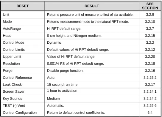
Table 8. Reset Settings ... 30
Table 9. Reset Calibration... 31
Table 10. Reset All ... 31
Table 11. Security Levels, Advanced Interface... 34
Table 12. Main Run Screen Fields and Buttons ... 42
Table 13. Lower Level Screen Displays and Selectable Fields ... 43
Table 14. Menu Structure... 49
Table 15. COM1 Pin Designations and Connections ... 75
Table 16. COM2 DB-9F Pin Designations ... 76
Table 17. Program Message List ... 83
Table 18. Error #s and Descriptions ... 85
Table 19. 8 Bit Status Byte Register ... 116
Table 20. 8 Bit Standard Event Register ... 117
Table 21. 8 Bit Ready Status Register ... 118
Table 22. Program Message List ... 118
Table 23. Calibration Point Sequence, A200K RPTs ... 127
Table 24. Calibration Point Sequence, A1.4M and A700K RPTs ... 127
Table 25. Calibration Point Sequence, A7M and A14M RPTs ... 127
Table 26. Calibration Point Sequence, BG15K RPTs ... 127
Table 27. PPC4E Troubleshooting Guide ... 139
Table 28. External Drivers Current Output ... 143
Table 29. External Drivers Pin Outs ... 143
Table 30. Pressure Unit of Measure Conversion Coefficients ... 144
Figures
Figure 1. PPC4E front panel ... 7
Figure 2. PPC4E rear panel ... 7
Figure 3. Dynamic Pressure Control Operation ... 14
Figure 4. Static Pressure Control Operation ... 15
Figure 5. Ready/Not Ready in Dynamic Pressure Control Mode ... 16
Figure 6. Ready/Not Ready in Static Control Mode ... 16
Figure 7. Main Run Screen Display and Selectable Fields (see Table 12) ... 41
Figure 8. Lower Level Screen Example (see Table 13) ... 43
Figure 9. Keypad layout ... 44
Figure 10. AutoRange Bar ... 51
Figure 11. Windows selection of Hyperterminal... 76
Figure 12. Hyperterminal Initial Display ... 76
Figure 13. Hyperterminal ASCII Setup ... 78
Figure 14. Status Register Schematic ... 116
Figure 15. Removing Back Cover ... 133
Figure 16. PPC4E Internal View ... 134
Figure 17. Pressure Control Module Schematic ... 136
Figure 18. PPC4E Reference Pressure Transducer Module Schematics ... 138
About This Manual
This manual is intended to provide the user with the basic information necessary to operate a PPC4E pressure controller/calibrator. It also includes a great deal of additional information provided to allow you to optimize PPC4E use and take full advantage of its many features and functions.
Before using the manual, take a moment to familiarize yourself with the Table of Contents structure: Sections 1, 2 and 3 should be read by all first time PPC4E users. Section 4 is important for those using the Advanced user interface. Section 5 is for remote operation from an external computer. Section 6 provides maintenance and calibration information. Section 7 is a quick troubleshooting guide. Use it to troubleshoot unexpected PPC4E behavior based on the symptom of that behavior. Certain words and expressions have specific meaning as they pertain to PPC4E. The Glossary, Section 10 is useful as a quick reference for exact definition of specific words and expressions as they are used in the manual.
Note
For those who “don’t read manuals”, go directly to Section 2.3 to set up your PPC4E and then go to Section 2.4 for power-up and verification. This will get you up and running quickly with a minimal risk of causing damage to yourself or your new PPC4E. THEN…when you have questions or start to wonder about all the great features you might be missing, get into the manual!
Manual Conventions
Note
• This manual is written for both PPC4E and PPC4EX. PPC4EX is a configuration of PPC4E with extended AutoRange turndown.
• When the term “PPC4E” is used alone, it typically refers to both PPC4E and PPC4EX collectively.
• Detailed description of menu structure, key press sequences and conventions are found in Section 4.
• For dedicated front panel keys, such as , , , and , any time a key is shown in the manual, it should be interpreted to mean “press this key”. For example: to return to the Main Run Screen means “Press the
button to return to the Main Run Screen”.
• The electronic version of this manual makes extensive use of hot links for the table of contents, figure references, table references and all section references found throughout. Simply click on a reference to follow the live link.
Caution
“Caution” is used throughout the manual to identify conditions or actions that could cause harm to the PPC4E or to the devices that are connected to the PPC4E.
Warning
“Warning” is used in throughout the manual to identify actions that could pose a hazard to the user of the PPC4E.
Note
“Note” is used throughout the manual to identify operating and applications advice and additional explanations.
1. Introduction
1.1 Product
Overview
PPC4E is a stand-alone pressure controller intended for precision setting and control of gas pressure into a closed volume as is commonly needed for the calibration and testing of pressure measuring instruments. It has been designed to provide very high performance combined with versatility and ease of use.
Model “PPC4E” is equipped one Reference Pressure Transducers (RPT) and model PPC4EX is equipped with two RPTs to allow it to set and measure pressure with low measurement uncertainty.
Pressure control is achieved by a patented pneumatic module based on digitally controlled solenoid valves and differential pressure regulators.
PPC4E is controlled locally by the operator using a front panel display, keypad and function keys or remotely by a computer using ASCII character command strings over RS232 or IEEE-488.2.
PPC4E models are available to support measure and control pressure in ranges from as low as - 1 to 1 kPa (-0.15 to 0.15 psi) to as high as 14 MPa (2 000 psi), and feature absolute, gauge and compound gauge pressure measurement modes.
1.2 Specifications
1.2.1 General
Specifications
Power Requirements 100 to 240 VAC (-15%, +10%), 50-60 Hz, 70 VA max consumption
Operating Temperature Range 10 to 40 °C
Storage Temperature Range -20 to 70 °C
Vibration Meets MIL-PRF-28800F Class 3
Weight 16.6 kg (36.5 lb)
Dimensions 19 cm H x 35 cm W x 45 cm D (7.5 in. x 13.8 in. x 17.7 in.)
Ventilation To prevent product overheating, provide proper ventilation. Allow 10 cm (4 in.)
clearance from rear panel cooling fan.
Microprocessors Motorola 68302, 16 MHz
Remote communication interfaces RS232 (COM1, COM2), IEEE-488.2, USB (front panel, firmware load only)
Fuses 1 A, 250 VAC fuse, 5 x 20 mm, time lag type fuse. Internal power supply fuse
not replaceable by operator: 2A, 250 V (UV 440-2 power supply), 3.15A, 250 V (NFS40-7612 power supply)
Pressure Ranges Vacuum to 14 MPa (2 000 psi) see Table 1.
Operating Medium Any clean, dry, non-corrosive gas
Warning
User is responsible for any and all safety precautions associated with hazardous, flammable or toxic gas ventilation and containment.
Pressure Connections TEST (+), TEST (-): 1/8 in. NPT F
SUPPLY: 1/8 in. NPT F EXHAUST: 3/8 in. NPT F
ATM: 10-32 UNF
Pressure Limits Maximum working:pressure: PPC4E range maximum
Maximum test pressure:w/out damage: 115 % of PPC4E range
1.2.2
Pressure Measurement Specifications
1.2.2.1 PPC4E Models and Ranges
PPC4E family of pressure controller/calibrator measurement and control ranges are achieved by using one internal reference pressure transducer (RPT) in PPC4E models and two RPTs in PPC4EX models. PPC4E and PPC4EX models with similar numeric model designations cover similar maximum pressure ranges, however the uncertainty of pressure measurements at the low end of the pressure range is a function of the AutoRanged Span (see Section 3.2.7). Uncertainties scale with AutoRanged spans as low as 10% of the controller span for PPC4E models and as low as 1% of the controller span for PPC4EX models.
All PPC4E and PPC4EX models have only one TEST(+) and TEST(-) port. PPC4E internal valves and logic handle switching between the two RPTs as needed.
Table 1. PPC4E Model Designations and Ranges
MODEL DESIGNATION Hi RPT Lo RPT PRESSURE RANGE1 Gauge [kPa]2 Gauge [psi]2 Absolute [kPa] Absolute [psi]
PPC4EX 14M A14M A1.4M -ATM to
14 000 -ATM to 2 000 0 to 14 000 0 to 2 000 PPC4E 14M A14M -
PPC4EX 7M A7M A700K -ATM to
7 000 -ATM to 1 000 0 to 7 000 0 to 1 000 PPC4E 7M A7M -
PPC4EX 1.4M A1.4M A200K -ATM to
1 400 -ATM to 200 0 to 1 400 0 to 200 PPC4E 1.4M A1.4M -
PPC4EX 100K A200K BG15K -ATM to
100 -ATM to 15 0 to 200 0 to 30 PPC4E 100K A200K - PPC4E 15K BG15K - ±15 ±2.2 - - 1
Pressure range is nominal measurement range. See pressure control specifications (Section 1.2.3) for lowest controllable pressure.
2 ATM represents the current atmospheric pressure. –ATM is the lowest pressure achievable in
negative gauge mode (vacuum).
Warm Up Time None required, 30 minute temperature stabilization recommended for best performance from cold power up
Resolution To 1 ppm, user adjustable Acceleration Effect ± 0.008 % /g maximum, worst axis
Allows operation at ± 20° from reference plane without significant effect
Predicted One Year Stability ± 0.005% of reading for gauge or negative mode or ± (0.005% + Constant uncertainty from Table 2) for absolute mode, k=2
Precision 0.019% of AutoRanged span or better for AutoRanged span equal to or greater than the Minimum AutoRanged span (see Table 2).
Table 2. PPC4E Measurement Uncertainty (Includes Precision)
Gauge Uncertainty1
Equal to % of AutoRanged span3
Absolute Uncertainty1
Equal to % of AutoRanged span + Constant4
Model % of AutoRanged span Minimum AutoRanged span [kPa]2 % of AutoRanged span Constant [kPa] Minimum AutoRanged span [kPa]2 PPC4EX 14M 0.02 140 0.02 0.1 140 PPC4E 14M 0.02 1 400 0.02 1 1 400 PPC4EX 7M 0.02 70 0.02 0.05 70 PPC4E 7M 0.02 700 0.02 0.5 700 PPC4EX 1.4M 0.02 14 0.02 0.014 70 PPC4E 1.4M 0.02 140 0.02 0.1 140 PPC4EX 100K 0.02 ± 1 0.02 0.014 70 PPC4E 100K 0.02 ± 10 0.02 0.014 70 PPC4E 15K 0.02 ± 1.5 - - -
1. Maximum deviation of the RPT indication from the true value of applied pressure including precision, predicted one year stability limit, temperature effect and calibration uncertainty, combined and expanded (k=2) following the ISO “Guide to the Expression of Uncertainty in Measurement.”
2. For AutoRange spans below the Minimum AutoRanged span uncertainty is equal to the value at the Minimum AutoRanged span.
3. Gauge uncertainty is a % of AutoRanged span. For example, an AutoRanged span of 3 500 kPa on model PPC4E 7M would have uncertainty of (0.02% * 3 500 kPa) = 0.70 kPa.
4. Absolute uncertainty is the sum of a % of AutoRanged span and a Constant that accounts for zero drift. For example, an AutoRanged span of 80 kPa on model PPC4EX 100K would have uncertainty of (0.02% * 80 kPa + 0.014 kPa) = 0.03 kPa.
1.2.2.2 On-Board
Barometer
The on-board barometer is used only to measure changes in atmospheric pressure to provide dynamic compensation of an absolute RPT’s atmospheric pressure offset in gauge measurement mode with PPC4E models other than PPC4E 15k.
Warm Up Time None required
Range 70 to 110 kPa (10 to 16 psi)
Resolution 0.001 % of span
1.2.3
Pressure Control Specifications
Control Precision
PPC4E:
±0.0006% of controller span PPC4EX:
±0.0006% of controller span (AutoRanged span >10% of controller span)
±0.00006% of controller span (AutoRanged span ≤10% of controller span)
Lowest controllable Pressure (gauge mode)
Zero set by automated venting. Lowest point above or below zero limited only by RPT resolution and control precision. Lowest controllable Pressure
(absolute, negative gauge modes)
1 kPa for all models except PPC4E 7M and PPC4E 14M 3.5 kPa for PPC4E 7M
7 kPa for PPC4E 14M Ultimate Pressure
(absolute, negative gauge) Depending on vacuum pump and connections
200 to 700 Pa (2 to 7 mbar, 0.03 to 0.1 psia) Typical Pressure Setting Ready Time
(0.005% hold limit, 50 cc test volume) 15 to 30 s Slew Time
(ATM to FS with 50 cc test volume) 30 s
Typical Test Volume 0 to 1000 cc for Controller Range of 1.4 MPa [300 psi] or less 0 to 500 cc for Controller Range greater than 1.4 MPa [300 psi] Default Dynamic Control Hold Limit ± 0.01 % of current range
2.
Installation
2.1
Unpacking and Inspection
2.1.1
Removing from Packaging
PPC4E is delivered in a corrugated container with suspension packaging; or in an optional molded shipping case with custom foam inserts.
Remove the PPC4E and its accessories from the shipping container and remove each element from its protective plastic bag.
2.1.2
Inspecting Contents
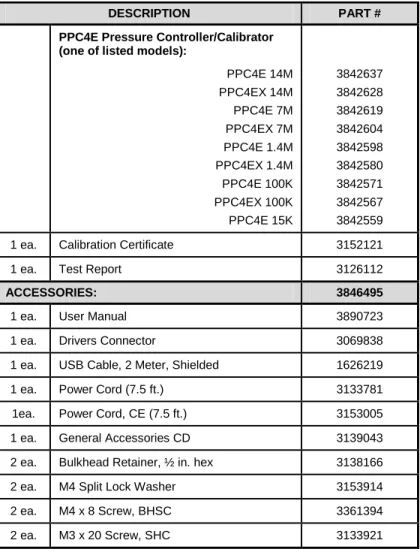
Check that all items are present and have no visible damage. A PPC4E includes all items indicated in Table 3.
Table 3. PPC4E Packing List
DESCRIPTION PART #
PPC4E Pressure Controller/Calibrator (one of listed models):
PPC4E 14M PPC4EX 14M PPC4E 7M PPC4EX 7M PPC4E 1.4M PPC4EX 1.4M PPC4E 100K PPC4EX 100K PPC4E 15K 3842637 3842628 3842619 3842604 3842598 3842580 3842571 3842567 3842559
1 ea. Calibration Certificate 3152121
1 ea. Test Report 3126112
ACCESSORIES: 3846495
1 ea. User Manual 3890723
1 ea. Drivers Connector 3069838
1 ea. USB Cable, 2 Meter, Shielded 1626219
1 ea. Power Cord (7.5 ft.) 3133781
1ea. Power Cord, CE (7.5 ft.) 3153005
1 ea. General Accessories CD 3139043
2 ea. Bulkhead Retainer, ½ in. hex 3138166
2 ea. M4 Split Lock Washer 3153914
2 ea. M4 x 8 Screw, BHSC 3361394
2.2
Site Requirements
The PPC4E can be installed on any flat, stable surface at a convenient height. The front feet can be extended so that the unit can be inclined for easier viewing. The PPC4E can also be mounted in a standard 19 in. rack using the optional rack mount kit.
Minimizing the distance between the PPC4E and the device or system under test will enhance control performance and reduce pressure setting times.
Ready access to the PPC4E rear panel should be considered to facilitate making and breaking pressure connections.
The Self Purging Liquid Trap (SPLT), if used, should be mounted vertically at the low point of the connection between the PPC4E TEST(+) port and the test (see Section 2.3.6.1).
PPC4E 15K and PPC4EX 100K must be set up with a Dual Volume Unit (DVU). Its location and connections should be considered (see Section 2.3.6.2).
Support facilities required include:
• An electrical power source of 100 to 240 VAC, 50 - 60 Hz.
• A continuous, regulated pressure supply of clean, dry, non-corrosive gas at PPC4E maximum control pressure + 10 % (70 kPa (10 psi) in the case of a PPC4E 15K) to be connected to the PPC4E
SUPPLY port. Lower gas pressure supply can be used but should exceed the maximum desired test output pressure by 10 to 20 %.
• A vacuum source of less than 1 psi absolute (7 kPa) and with displacement of at least 90 lpm (3 cfm) if control of pressures under 3 psi (20 kPa) gauge is desired.
2.3
Setup
2.3.1
Preparing for Operation
To prepare PPC4E for check out and operation:Remove the plastic caps from the PPC4E rear panel pressure connections. Remove the protective plastic sheet from the front panel display.
Familiarize yourself with the front and rear panel (see Section 2.3.2). Then proceed with Sections 2.3.3 to 2.3.9.
2.3.2
Front and Rear Panels
2.3.2.1 Front Panel
Ready/Not Ready indicator
Controlled pressure measurement
Display
Multi-function keypad
Vent Indicator
Direct pressure control keys
Cursor control keys
Select and Enter knob
Remote activity indicator
USB connection Figure 1. PPC4E front panel
2.3.2.2 Rear Panel
ATM port COM2 Connector IEEE-488 Connector COM1 Connector Power Switch Fuse Electrical Power Connector (IEC-320-C13)
Product Label
Drivers (12 V) Connector
Pressure Connection, TEST(+)
Pressure Connection, TEST(-)
Pressure Connection, SUPPLY
Pressure Connection, EXHAUST
2.3.3
Power Connection
Check that the PPC4E power switch is OFF.
Connect the supplied power cable to the rear panel power module.
Connect the other end of the power cable to an electrical supply of 100 to 240 VAC, 50-60 Hz.
2.3.4
Connecting to a Pressure Supply (Supply Port)
Using a pressure connecting hose or tube of appropriate pressure rating, connect the pressure supply to the SUPPLY port on the rear panel of PPC4E. The PPC4E SUPPLY port connection is 1/8 in. NPT female.
The supply pressure should be equal to the maximum PPC4E control pressure + 10 % (or 70 kPa (10 psi) for a PPC4E 15K). Lower gas pressure sources can be used but should exceed the maximum desired test output pressure by 10 to 20 %.
Caution
Never connect a pressure supply greater than 20 % over the maximum pressure of the PPC4E maximum pressure range (except with PPC4E 15K as specified). Be sure to connect the pressure supply to the SUPPLY port. Connecting to another port can damage the PPC4E.
2.3.5
Connecting a Vacuum Pump (Exhaust Port)
For PPC4E to set pressures under atmosphere and/or to reliably set pressure under 20 kPa (3 psi) gauge (other than zero gauge), a vacuum supply must be connected to the EXHAUST
port.
Caution
• Never connect a pressure supply to or plug the PPC4E EXHAUST port.
• To avoid building up pressure on the EXHAUST port or on a vacuum pump connected to the EXHAUST port, the vacuum source should either be continuously ON or the EXHAUST port should be bypassed to atmosphere when the vacuum source is OFF. This is because when a supply pressure is applied to the PPC4E SUPPLY port and the PPC4E is NOT in the vent ON condition, there is typically a constant gas exhaust through the PPC4E EXHAUST port.
Note
To ensure optimum pressure control when changing the pressure applied to the EXHAUST port from vacuum to atmosphere or vice-versa, be sure to change the control reference setting if the setting is NOT in AUTO mode (see Section 3.2.25.1).
2.3.6
Connecting to the Device Under Test (Test(+) and
Test(-) Ports)
If you are using a self purging liquid trap (SPLT), see Section 2.3.6.1 before proceeding to connect the device under test.
If the PPC4E is model PPC4E 15K or PPC4EX 100K, a dual volume unit (DVU) should be installed for very low pressure control. See Section 2.3.2.2 before proceeding to connect to the device under test.
Using a pressure connecting hose or tube of appropriate pressure rating, connect the device or system to be tested to the PPC4E TEST(+) port. The PPC4E TEST(+) connection is 1/8 in. NPT female.
PPC4E TEST(+) AND TEST(-) PORTS
All PPC4Es have a TEST(+) and a TEST(-) port. See Figure 18 for configuration of Reference Pressure Transducers (RPTs) and the internal barometer in the different PPC4E models.
• When operating in absolute mode: The TEST(-) port is left open to atmosphere.
• When operating in gauge or negative gauge mode with a range greater than 50 kPa (7.5 psi): The TEST(-) port is normally left open to atmosphere. A possible exception is when the device or system under test is in an ambient pressure that may differ significantly from the ambient pressure around the PPC4E. For example, if the PPC4E is controlling pressure into UUTs in an environmental chamber, the pressure in the environmental chamber may be different from ambient pressure around the PPC4E. In this case, connecting a tube from the TEST(-) port to the inside of the chamber may improve measurement results. This tube must be left open to the environment so that the pressure inside cannot deviate too far from ambient.
• When operating in gauge or negative gauge mode with a range less than 50 kPa (7.5 psi): As a general rule, it is preferable to connect the PPC4E TEST(-) port(s) directly to the low or reference side of the device under test to ensure that these are at the same pressure. In most cases, this tube must be left open to the environment so that the pressure inside cannot deviate too far from ambient. The exception is when using a PPC4E 15K or PPC4EX 100K AutoRanged to 10 kPa or less, for which more stable results may be obtained by closing this connectionoff from ambient pressure to reduce line pressure fluctuations.
Caution
• Do not apply pressure to the TEST(+) port without having a pressure supply equal to or greater than the applied pressure connected to the SUPPLY port. When controlling pressure to the TEST(+) port externally, do not cause the pressure to change at a rapid rate. For example, do not vent suddenly by opening an external valve. Internal damage to the PPC4E may result.
• Do not connect a pressure supply to the TEST(-) port. The pressure applied to this port should be maintained at atmospheric pressure, between 70 and 110 kPa (10 and 16 psia). Exceeding these limits may damage the PPC4E.
• Operating the PPC4E connected to a system with liquid contaminants without taking proper precautions to purge the system and test line may cause contamination of the PPC4E that will require non-warranty service.
Note
• Minimizing the length of the test connection tubing will enhance control performance and reduce pressure setting time. For normal operation, the total volume of the device or system under test including connecting tubing should be less than 1 000 cc (60 in3) up to 2 000 kPa (300 psi) and less than 500 cc (30 in3) above 2 000 kPa (300 psi).
• PPC4E pressure control will not operate properly if there are excessive leaks in the test system. In general, the maximum acceptable leak rate for optimal PPC4E automated pressure control operation and to ensure in tolerance measurements with default pressure control parameters is ± 0.5 % of set pressure/minute. In DYNAMIC CONTROL mode, to handle higher test system leak rates, increase the hold limit using CUSTOM CONTROL (see Section 3.2.12).
• PPC4E pressure control may be adversely affected if the test connection tubing is too restrictive. For optimum results, the inner diameter of the connecting hose should be at least 1.75 mm (0.07 in.).
2.3.6.1 Installing a Self Purging Liquid Trap (SPLT)
The SPLT (optional) is intended to collect and exhaust liquid or other contaminants that may be present in the device or system under test so that they do not return to contaminate the PPC4E.
The SPLT is installed in the TEST(+) connection line at a low point between PPC4E and the device or system under test.
See the SPLT Operation and Maintenance manual for more complete instructions on SPLT installation.
2.3.6.2 Installing a Dual Volume Unit (DVU), PPC4E 15 K
and PPC4EX 100K
To achieve in tolerance pressure control with the very low range of the PPC4E 15K and PPC4EX 100K, a PK-PPC-BG-DVU dual volume unit should be installed in-line on the TEST(+) and TEST(-) ports. The DVU includes two thermally isolated volumes installed in the test line to improve control stability.
See the PK-PPC-BG-DVU instruction sheet for additional information on its installation.
2.3.7
The ATM Port
The PPC4E ATM port is the system vent to atmosphere point used to set zero gauge pressure as well as to obtain reference pressure measurements of atmospheric pressure. Although a pressure hose can be connected to the ATM port to direct the vented gas flow, a completely unobstructed connection to atmosphere must be maintained for PPC4E reference pressure measurements to operate normally.
The PPC4E ATM port fitting is 10-32 UNF.
Caution
NEVER plug, obstruct or connect a supply pressure to the PPC4E ATM port. This may adversely affect GAUGE mode operation.
2.3.8
Check/Set Security Level
PPC4E has a security system based on user levels. By default, the security system is set to “low”, which includes certain access restrictions, and there is no password required to change the security level. See Section 3.2.24.4 for information on the security level system. As part of the PPC4E startup, determine the security level that is appropriate for the PPC4E and set a password if desired.
Caution
PPC4E is delivered with the security level set to “low” to avoid inadvertent altering of critical internal settings but with access to changing security levels unrestricted. It is recommended that the low security level be maintained at all times and password protection be implemented if control over setting of security levels is desired.
2.3.9
Turn Off Absolute and Negative Gauge Mode
Most PPC4E onfigurations are able to operate in gauge, negative gauge and absolute measurement modes (see Section 3.2.10). PPC4E 15K operates only in gauge or negative gauge mode. If the PPC4E will be used only in gauge mode, the other measurement modes can be turned off so they are no longer accessible. This can avoid confusion and/or accidental use of the wrong measurement mode. See Section 0 for complete information on turning off absolute and negative gauge measurement modes.
2.4
Power-Up And Verification
2.4.1
Switch Power On
Actuate the power switch on the PPC4E rear panel. Observe the front panel display as PPC4E initializes error checks and goes to the Main Run Screen (see Section 4.1).
PPC4E power-up condition is ranged to the PPC4E maximum pressure, VENT ON unless the pressure measured by the active reference pressure transducer is more than 20 kPa (3 psi) away from standard atmospheric pressure.
If the PPC4E fails to reach the Main Run Screen, service is required. Record the sequence of operations and displays observed.
2.4.2
Check Pressure Measurement Operation
2.4.2.1 Checking Absolute Mode Pressure Measurement
If the PPC4E is not vented (VENT LED OFF), to vent the PPC4E (VENT LED ON) (see Section 3.2.13) and wait for a Ready indication (see Section 3.2.3). Use the PPC4E AutoRange function to select or configure an absolute pressure range near the maximum pressure of the PPC4E (see Section 4.7.1). Verify the PPC4E is vented. Observe the current value of atmospheric pressure. Check that the value agrees with the local value of atmospheric pressure within PPC4E measurement tolerance as applicable (see Section 1.2.3). If they do not agree within tolerances, the PPC4E may require repair or calibration.If the PPC4E is model PPC4EX 1.4M, PPC4EX 7M or PPC4EX 14M, use the PPC4E AutoRange function to select or configure gauge pressure range near 8% of the maximum absolute pressure of the PPC4E (see Section 4.7.1). Verify the PPC4E is vented. Check that the value agrees with the local value of atmospheric pressure within PPC4E measurement tolerance as applicable.
2.4.2.2 Checking Gauge Mode Pressure Measurement
If the PPC4E is not vented, to vent it (see Section 3.2.13).
Note
It is normal for PPC4E to indicate a value other than zero when vented when gauge mode is first entered or ranges are changed. After about ten seconds, the vent LED should flash and zero should be indicated.
Use the PPC4E AutoRange function to select or configure gauge pressure range near the maximum pressure of the PPC4E (see Section 4.7.1). Verify the PPC4E is vented. Observe that, within ten seconds, zero pressure is indicated. It is normal for PPC4E to indicate a value other than zero for up to ten seconds when first entering gauge mode.
If a “PPC4EX” model, use the PPC4E AutoRange function to select or configure gauge pressure range near 5% of the maximum gauge pressure of the PPC4E (see Section 4.7.1). Verify the PPC4E is vented. Observe that, within ten seconds, zero pressure is indicated.
2.4.3
Leak Test
2.4.4
Purge
If an SPLT is included and installed in the test line (see Section 2.3.6.1) and the Device Under Test (UUT) may be contaminated with liquids, perform a purge of the UUT (see Section 3.2.25.4). The Purge function must first be enabled (see Section 4.7.12.3). This will help to expel contaminating liquids from the UUT.
Caution
Operating the PPC4E connected to a system with liquid contaminants without taking proper precautions to purge the system and test line may cause contamination of the PPC4E that will require non-warranty service.
2.4.5
Check Pressure Control Operation
Select a pressure range using [AutoRange], Range: (see Section 4.7.1).
Select dynamic control mode with the control mode shortcut (see 4.6.1 and Section 4.7.8.2). to return to the Main Run Screen.
, key in a target pressure within the active range and . (see Section 4.5.1).
Caution
Verify the maximum pressure rating of the system connected to the PPC4E TEST(+) port before entering a target pressure. Do not enter a target pressure greater than the pressure rating of the system connected to the PPC4E TEST(+) port.
PPC4E should set the target pressure and indicate Ready (see Section 3.2.3) continuously in 15 to 60 seconds. If it does not, see Section 7 to troubleshoot.
2.5
Short Term Storage
The following procedure is recommended for short term storage of PPC4E: Vent the PPC4E test pressure.
Turn the power OFF using the rear panel power switch. Shut OFF or disconnect the pressure supply.
Shut OFF or disconnect the vacuum supply. Be sure the pressure supply is disconnected or the vacuum pump is bypassed from the PPC4E EXHAUST port before turning OFF the vacuum pump.
3.
Operating Principles
3.1
User Interface
PPC4E features a graphical user interface for bench top operation, and remote communications for computer controlled applications such as automated calibration or testing. See Section 4 for operation information when using the graphical user interface.
Remote communication is by RS232 (COM1) or IEEE-488. See Section 5 for specific information on remote communication.
3.2
General Operating Principles
3.2.1
Direct Pressure Control
PURPOSEThe direct pressure control keys provide direct manual control to increase, decrease, and jog the PPC4E pressure.
OPERATION
or cause pressure to increase or decrease at the fast slew rate.
or when dynamic control is not active cause pressure to increase or decrease at the slow slew rate.
or during dynamic control causes the pressure to jog or step by a fixed amount. During active pressure control, they cause the target pressure to be changed by the fixed amount. One press causes one step. The approximate value of the step is set automatically depending on the current active PPC4E range. The value can be adjusted with the Jog function (see Section 3.2.18).
Caution
The fast direct pressure control keys, and , interrupt and override automated pressure control.
3.2.2
Automated Pressure Control
PPC4E automated pressure control provides automated adjustment and control of pressure to a user designated target value. from the Main Run Screen allows a pressure control target value to be entered and executed. or cause active pressure control to be interrupted. Sending a remote command when in local mode also interrupts pressure control. PPC4E supports two pressure control modes to meet different pressure setting and controlling requirements: dynamic and static. Pressure control parameters for each control mode are automatically set to optimal default values for the operating PPC4E range when the range is selected or AutoRange is used (see Section 3.2.7. Control parameters can be customized using screen selections (see Section 4.7.8.2.1).
Control parameters:
Target Pressure The pressure set point specified by the operator.
Hold Limit A symmetrical positive and negative limit around the target value within which the controlled pressure is maintained.
Stability Limit A rate of change of pressure limit in units of pressure/second used as a criterion for the Ready/Not Ready condition in static control or when PPC4E is idle (control not active).
Note
See Sections 3.2.2.1 and 3.2.2.2 (Dynamic Control and Static Control) for a detailed explanation of each control mode and its advantages, the default control parameters and the control customization options.
3.2.2.1 Dynamic Control
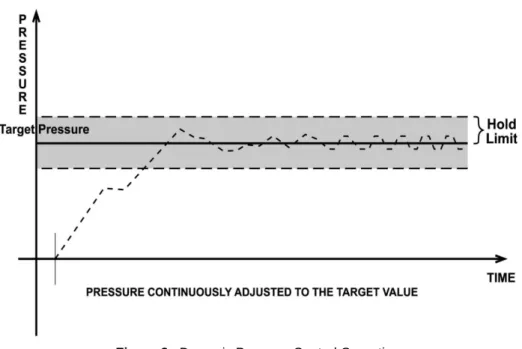
Dynamic control mode is designed to set the pressure to the target value and control continuously to keep pressure within the hold limit and as close to the target value as possible (see Figure 3) The advantage of this control mode is that the final pressure achieved is the same as the target value. The maximum value of the control error is equal to the hold limit. The average value of the control error is typically much smaller than the hold limit.
During dynamic pressure control, the hold limit is active. If the pressure goes outside of the hold limit, a Not Ready condition occurs. See Table 6 and Table 7 for default hold limit values. To customize the hold limit see Section 4.7.8.2.1.
Figure 3. Dynamic Pressure Control Operation
3.2.2.2 Static Control
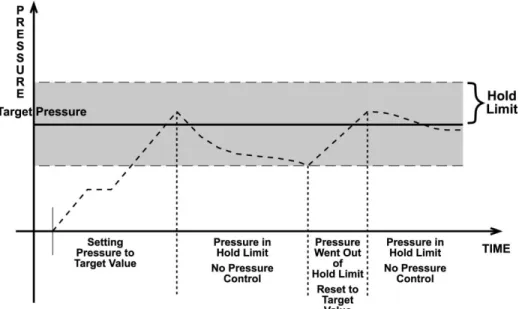
Static control mode is designed to set the pressure near the target value and then interrupt active control to allow pressure to stabilize naturally within the hold limit. The advantage of this control mode is that pressure can be set and/or measured within a defined limit of a target without interference from the pressure control system. In a system without excessive leaks, the pressure stability achieved may be greater than the stability with which the pressure control system can actively control pressure. Using static control to control pressure near the desired set point and then measuring back the stabilized pressure without interference of the control function can allow control errors to be completely eliminated. However, the final pressure achieved is not equal to the target value. During static pressure control, the hold limit is active. If the pressure goes outside of the hold limit, a Not Ready condition occurs (see Section 3.2.3) and pressure is readjusted to the target value (see Figure 4). For default values for hold and stability limits, see Table 6 and Table 7. To customize the hold and stability limits see Section 4.7.8.2.1.
Figure 4. Static Pressure Control Operation
3.2.3
Pressure Ready/Not Ready
A Ready/Not Ready indication on the PPC4E display is intended to provide the user with a clear and objective criterion for determining when a valid pressure measurement can be made.
The Ready/Not Ready indications are:
<Green> Pressure Ready. PPC4E is either actively controlling the pressure and the criteria for a Ready condition to occur have been met or PPC4E is NOT actively controlling the pressure and the rate of change of pressure is within the stability limit.
<Yellow> Pressure Near Ready. PPC4E is actively controlling the pressure using fine pressure control and is close to meeting the criteria for a
Ready condition.
<Red > Pressure Not Ready. Either PPC4E is idle and pressure does not meet the stability test or PPC4E is actively controlling the pressure and Ready conditions have not yet been met.
When pressure control is NOT active: A Ready condition occurs any time NO control valve is operating and the pressure rate of change is inside the stability limit. The stability limit is defined in terms of rate of change of pressure in current pressure units per second.
When pressure control is active: The criteria for determining the Ready/Not Ready condition depend on whether the current control mode is static or dynamic. Pressure Ready/Not Ready parameters are set by default when AutoRange is used, or a control mode is selected. The parameters can be customized if desired (see Section 4.7.8.2.1).
Dynamic Control Ready/Not Ready
With dynamic pressure control active, a Ready condition occurs whenever:
• The current measured pressure is inside the hold limit.
Note
In dynamic control mode, it is common to assume that when a Ready condition occurs (pressure inside the control hold limit), the measured pressure equals the target pressure. For this reason, when the pressure is Ready in dynamic control mode, the measured pressure display is equal to the target pressure.
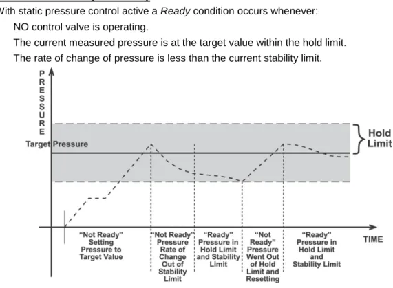
Figure 5. Ready/Not Ready in Dynamic Pressure Control Mode Static Control Ready/Not Ready
With static pressure control active a Ready condition occurs whenever:
• NO control valve is operating.
• The current measured pressure is at the target value within the hold limit.
• The rate of change of pressure is less than the current stability limit.
Figure 6. Ready/Not Ready in Static Control Mode Ready/Not Ready When Not Actively Controlling
When NO automated pressure control is active, Ready is indicated whenever the rate of change of pressure is less than the current stability limit (see Section 4.7.8.2.1).
3.2.4
Gauge and Negative Gauge Modes with an Absolute
Reference Pressure Transducer, Dynamic
Compensation for Atmospheric Pressure
All RPTs used in PPC4E, with the exceptions of the Hi RPT in PPC4E 15K and the Lo RPT in PPC4EX 100K, are intrinsically absolute but they are also used in gauge and negative gauge measurement modes (difference from atmosphere) (see Section 3.2.10). Gauge measurement mode is achieved by subtracting the value of atmospheric pressure, Poffset,G, from the RPT’s
absolute reading. In gauge or negative gauge measurement mode, the routine that measures Poffset,G, is run automatically whenever the PPC4E is in the vented condition. This
ensures the continuous automated updating of the Poffset,G value corresponding to atmospheric
pressure. Gauge pressure is the measured absolute pressure, Pu, minus the atmospheric
offset.
Pgauge = Pu - Poffset,G
However, atmospheric pressure can change between opportunities to update the value of
Poffset,G, for example when running an extended test without venting. PPC4E uses dynamic
compensation of atmospheric pressure to correct for these changes in atmospheric pressure. When Poffset,G is determined, the reading of PPC4E’s on board barometer, Patm,0, is
also recorded. Later, when no longer vented, the change in atmospheric pressure, ΔPatm
since Poffset,G was updated is the difference between the current barometer reading, Patm, and
the barometer reading at Vent, Patm,0:
ΔPatm = Patm - Patm,0
Dynamic compensation for atmospheric pressure uses ΔPatm to correct the value of Poffset,G,
thus always compensating real time for changes in atmospheric pressure:
Pgauge = Pu - Poffset,G - ΔPatm
Any additional uncertainty in gauge pressure mode due to the dynamic compensation for atmospheric pressure technique is a function of the resolution and short term stability of the on-board barometer rather than its absolute measurement uncertainty. This additional uncertainty is ± 1 Pa (0.00015 psi), and is included in the PPC4E total uncertainty specification.
3.2.5
Multiple RPTs
To obtain low uncertainty, traceable pressure measurement, PPC4E uses Quartz Reference Pressure Transducers (RPT). One or two RPTs can be built into the PPC4E. The use of multiple RPTs (in the case of PPC4EX) is managed by PPC4E transparently to the operator. The use of multiple RPTs, combined with PPC4E’s infinite ranging capability and AutoRange feature (see Section 3.2.7), make it possible for a single PPC4E pressure controller/calibrator system to cover an extremely wide range of test ranges and measurement modes with low uncertainty in each range.
The PPC4E RPT function (see Section 4.7.1, RPT Search) is used to identify RPTs in the PPC4. The PPC4E manages the RPTs transparently to the operator, selecting the appropriate RPT for the range of operation and operating valves to connect and disconnect as needed.
Each RPT has a default range, which is its maximum range. It can also be downranged using PPC4E’s AutoRange function.
The PPC4E internal pneumatic layout for handling RPTs depends on the PPC4E model. Figure 18 provides pneumatic schematics of the different PPC4E internal RPT configurations with a chart of valve status for various operating conditions.
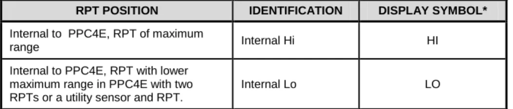
Position Identification of RPTs In a PPC4E System
Position identification of the currently active RPT or utility sensor is displayed by selecting
[AutoRange] and viewing the RPT: field. See Table 4 for position designation protocol for the RPTs available in a PPC4E system.
Table 4. Position Designators of RPTs in a PPC4E System
RPT POSITION IDENTIFICATION DISPLAY SYMBOL*
Internal to PPC4E, RPT of maximum
range Internal Hi HI
Internal to PPC4E, RPT with lower maximum range in PPC4E with two RPTs or a utility sensor and RPT.
Internal Lo LO
3.2.6
Multiple Ranges (RPTs, AutoRange and Infinite
Ranging)
A PPC4E range is defined as a pressure span and associated settings.
A PPC4E may have multiple ranges. Each RPT available to the PPC4E system has a default range which is its maximum span. Additional ranges, lower than the RPT’s maximum span, may be created using AutoRange (see Section 3.2.7). Ranges created using AutoRange may be saved with all their settings for reactivation later (see Section 4.7.1).
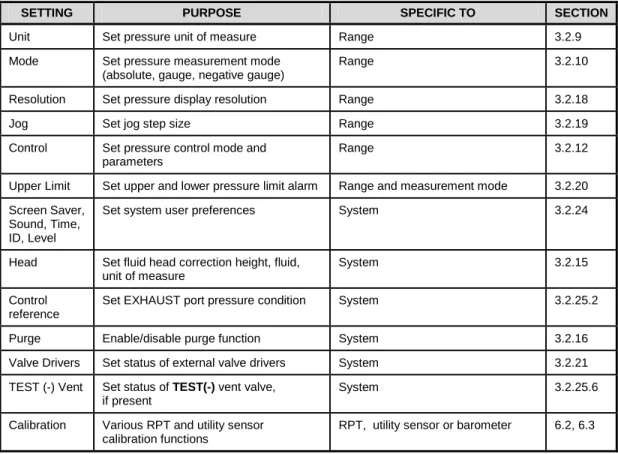
Most settings made in a PPC4E range, such as unit of measure, measurement mode, display resolution, control mode and control parameters are specific to the range. Many settings made while a range is active apply to that range and not other ranges. The range specific settings are stored with the range and recalled whenever the range is made active. This makes setting up and saving ranges a convenient way to store and recall frequently used operating configurations. See Table 5 for a listing of PPC4E adjustments and settings and whether they are range, RPT or system specific.
The ranges available on a PPC4E system may be queried (Range) and/or created (AutoRange) with functions available locally (see Section 4.7.1).
Table 5. Settings and What They Are Specific To (Range, Measurement Mode, RPT, System)
SETTING PURPOSE SPECIFIC TO SECTION
Unit Set pressure unit of measure Range 3.2.9
Mode Set pressure measurement mode (absolute, gauge, negative gauge)
Range 3.2.10
Resolution Set pressure display resolution Range 3.2.18
Jog Set jog step size Range 3.2.19
Control Set pressure control mode and parameters
Range 3.2.12
Upper Limit Set upper and lower pressure limit alarm Range and measurement mode 3.2.20 Screen Saver,
Sound, Time, ID, Level
Set system user preferences System 3.2.24
Head Set fluid head correction height, fluid, unit of measure
System 3.2.15
Control reference
Set EXHAUST port pressure condition System 3.2.25.2
Purge Enable/disable purge function System 3.2.16
Valve Drivers Set status of external valve drivers System 3.2.21
TEST (-) Vent Set status of TEST(-) vent valve, if present
System 3.2.25.6
Calibration Various RPT and utility sensor calibration functions
RPT, utility sensor or barometer 6.2, 6.3
3.2.7
AutoRange
PURPOSE
To automatically set up PPC4E to optimize its measurement and control characteristics and features to cover a specific pressure range. AutoRange functions create new ranges or select from existing saved ranges.
PRINCIPLE
PPC4E is designed to support the calibration and test of a very wide variety of test ranges in various measurement modes with a single pressure controller system.
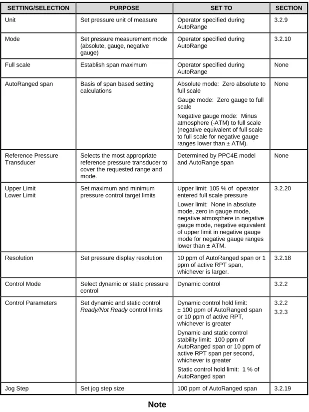
The AutoRange function determines which internal reference pressure transducer is used (for PPC4EX models) and simplifies the task of setting controller parameters appropriately for a specific test range. These are set automatically based on operator entry of desired measurement mode, pressure unit of measure and range full scale. The selections and default settings made by AutoRange are summarized in Table 6.
Table 6. Settings Made by AutoRange
SETTING/SELECTION PURPOSE SET TO SECTION
Unit Set pressure unit of measure Operator specified during AutoRange
3.2.9
Mode Set pressure measurement mode
(absolute, gauge, negative gauge)
Operator specified during AutoRange
3.2.10
Full scale Establish span maximum Operator specified during AutoRange
None AutoRanged span Basis of span based setting
calculations
Absolute mode: Zero absolute to full scale
Gauge mode: Zero gauge to full scale
Negative gauge mode: Minus atmosphere (-ATM) to full scale (negative equivalent of full scale to full scale for negative gauge ranges lower than ± ATM).
None
Reference Pressure Transducer
Selects the most appropriate reference pressure transducer to cover the requested range and mode.
Determined by PPC4E model and AutoRange span
None
Upper Limit Lower Limit
Set maximum and minimum pressure control target limits
Upper limit: 105 % of operator entered full scale pressure Lower limit: None in absolute mode, zero in gauge mode, negative atmosphere in negative gauge mode, negative equivalent of upper limit in negative gauge mode for negative gauge ranges lower than ± ATM.
3.2.20
Resolution Set pressure display resolution 10 ppm of AutoRanged span or 1 ppm of active RPT span, whichever is larger.
3.2.18
Control Mode Select dynamic or static pressure control
Dynamic control 3.2.2
Control Parameters Set dynamic and static control Ready/Not Ready control limits
Dynamic control hold limit: ± 100 ppm of AutoRanged span or 10 ppm of active RPT, whichever is greater Dynamic and static control stability limit: 100 ppm of AutoRanged span or 10 ppm of active RPT span per second, whichever is greater
Static control hold limit: 1 % of AutoRanged span
3.2.2 3.2.3
Jog Step Set jog step size 100 ppm of AutoRanged span 3.2.19
Note
• AutoRanged ranges cannot have altitude units (ft, m)
OPERATION
3.2.8
Range
PURPOSETo view and/or change the active pressure measurement range and associated settings.
Note
See AutoRange to create ranges (see Section 3.2.7) or to select ranges (see Section 4.7.1).
PRINCIPLE
A PPC4E range is defined as a pressure span and associated settings (see Section 3.2.7). A PPC4E may have multiple ranges. Each RPT available to the PPC4E system has a default range which is its maximum full scale. Additional ranges, lower than the RPT’s full scale, may also be created using AutoRange (see Section 3.2.7). Ranges created using AutoRange may be saved with all their settings for reactivation (see Section 4.7.1).
Range allows the available PPC4E pressure ranges to be viewed and selected.
Note
• Range full scale limits are given in the pressure unit that is currently active for that range. Change the active unit to display the range limits in a different unit.
• Many PPC4E settings and functions are range specific. See Table 5 for identification of range specific settings.
• To protect against overpressure situations and for maximum measurement performance, the active range can only be changed when the system is vented. When prompted by the PPC4E, causes PPC4E to vent and then complete the range change.
3.2.9
Unit
PURPOSETo select the unit of pressure in which PPC4E displays pressure values.
Note
For information on selecting the measurement mode (absolute, gauge, negative gauge), see Section 3.2.10.
PRINCIPLE
PPC4E allows the unit of measure in which pressure values are displayed to be changed. PPC4E supports 18 predefined pressure units of measure as well as up to five user defined units. See Table 30, Section 8.2.1, for a listing of the available units of measure and the conversion
factors used by PPC4E.
User defined unit definitions specify the number of user units per Pascal (Pa). 1 kiloPascal (kPa), for example, is specified by 0.001 units/Pa.
Note
• The pressure measurement unit selected is range specific. When in a given range, all functions and settings are represented in the current measurement unit for that range. However, certain internal and/or metrological functions (e.g., RPT calibration coefficients) are always represented in Pa regardless of the active range unit of measure.
• When the active unit is an altitude unit, the range and upper limit indications are in kPa if the unit is meters (m) and psi if the unit is feet (ft).
• If the pressure unit selected is a water column (inches, millimeters, meters) the reference temperature for water density must be specified.
During local operation with the graphical user interface, the temperature is included as part of the unit name, such as mmH20@4C. For remote selections the temperature is assumed to be 20 ºC unless specified in the Unit remote command (see Section 5.4.4).
OPERATION
See Section 4.7.6.1.
3.2.10 Measurement Mode
PURPOSETo set the measurement mode (absolute, gauge or negative gauge) for the active range. PRINCIPLE
PPC4E supports simple, one-step switching between up to three different measurement modes:
Absolute Measures pressure relative to vacuum (zero is hard vacuum). Range is from zero absolute to full scale.
Gauge Measures pressure relative to atmosphere, ATM (zero is ambient pressure). Range is from zero gauge to full scale, full scale must be greater than zero.
Negative gauge Measures pressure relative to atmosphere, ATM (zero is ambient pressure). Values are positive and negative, with ranges from negative one atmosphere (-ATM) to positive full scale. If the full scale is less than +ATM, the range is defined from the negative equivalent of positive full scale to positive full scale (for example, -10 kPa to 10 kPa gauge).
When changing measurement modes for a range, if the full scale of the range is 700 kPa (100 psi) or greater, the full scale is the same in both absolute and gauge modes. If the full scale is less than 700 kPa (100 psi), the gauge mode full scale is 100 kPa (14.5 psi) lower than the absolute mode full scale. Gauge and negative gauge mode, when available, have the same full scale.
Note
• Certain PPC4E settings are range AND measurement mode specific. See Table 5 for a listing of settings and what they are specific to.
• Absolute and negative gauge modes can be turned OFF in the calibration function (see Section 0). When absolute and negative gauge mode are turned OFF, only gauge mode can be activated.
OPERATION
See Section 4.7.6.2.
3.2.11 Set Pressure Automatically
PURPOSETo use the automated pressure control functions of PPC4E to set and maintain target pressure values. opens the target screen to initiate the sequence.
Note
• A target pressure entry that exceeds the current upper limit (see Section 3.2.20) or that is out of range will not be accepted as the target value.
• If PPC4E is unable to control pressure or appears to control pressure poorly, see Section 7 to troubleshoot.
• For PPC4E to set pressures under atmosphere and/or to reliably set pressures under 20 kPa (3 psi) gauge other than zero gauge, a vacuum