Dell | Cloudera Solution
Reference Architecture v2.1.0
A Dell Reference Architecture Guide
Table of Contents
Tables 3 Figures 4 Overview 5 Summary 5 Abbreviations 5Dell | Cloudera Solution 6
Solution Overview 6
Solution Taxonomy 7
Dell | Cloudera Solution Hardware Architecture 8
High-level Architecture 8
Dell | Cloudera Sizing Terms 9
Server Infrastructure Options 11
Dell | Cloudera Solution Network Architecture 28
Network Components 28
Dell Open Switch Solution 34
IPv6 Capabilities 35
Network Connectivity 35
Dell | Cloudera Solution Software Architecture 37
Linux File System Configuration Definition 37
Disk Partitioning Recommendation for the Name Node 37
Configuration Parameters: Recommended Values 37
Dell | Cloudera Solution Cloudera Enterprise Software 40
Deployment Integration 40
Cloudera Manager 40
Cloudera Support 41
HDFS Highly Available Name Nodes 42
Dell | Cloudera Solution Deployment Methodology 43
Site Preparation Needed for the Deployment 43
Dell | Cloudera Solution Hardware Monitoring and Alerting 43
Nagios 44
Ganglia 44
Dell | Cloudera Solution Security Design 44
What is Available in CDH4? 44
Implementing Secure Hadoop 44
Appendix A : Bill of Materials – PowerEdge C8000 Series 46
Appendix B : Bill of Materials – PowerEdge R720xd Nodes 55
Appendix C : Bill of Materials – PowerEdge R720 Nodes 56
Appendix D : Bill of Materials – PowerEdge R720xd Data node 58
Appendix E : Bill of Materials – PowerEdge C6105 60
Appendix F : Bill of Materials – Force10 Network Equipment 61
Network Equipment Notes 63
Appendix I : Dell | Cloudera Solution Components ‘Decoder Ring’ 66
Appendix J : External References 67
Update History 68
Changes in Version 2.1 68
To Learn More 68
Tables
Table 1: Dell | Cloudera Solution Use Cases 7
Table 2: Dell | Cloudera Solution Software Locations 9
Table 3: Cluster Sizes – PowerEdge C8000 Series 12
Table 4: Hardware Configurations – PowerEdge C8000 Compute Sleds 13 Table 5: Hardware Configurations – PowerEdge C8000 Storage Sleds 13 Table 6: Chassis Configuration – PowerEdge C8000 Master Chassis 14 Table 7: Chassis Configuration – PowerEdge C8000 High Availability Chassis 14 Table 8: Chassis Configuration – PowerEdge C8000 Data Nodes 14 Table 9: Chassis Configuration – PowerEdge C8000 ‘Heavy’ Data Nodes 15
Table 10: Rack Configuration – PowerEdge C8000 16
Table 11: Rack Configuration – PowerEdge C8000 ‘Heavy’ nodes 17
Table 12: Cluster Sizes – PowerEdge R720xd 20
Table 13: Hardware Configurations – PowerEdge R720xd 20 Table 14: Hardware Configurations – PowerEdge R720/R720xd 22 Table 15: Rack Configuration – PowerEdge R720xd (or R720/R720xd) 23 Table 16: Cluster Sizes—PowerEdge C6105 with PowerEdge R720 25 Table 17: Hardware Configurations—PowerEdge C6105 with PowerEdge R720 26
Table 18: Rack Configuration – PowerEdge C6100 27
Table 19: Single Rack Network Equipment 30
Table 20: Multi Rack Network Equipment 32
Table 21: Dell | Cloudera Solution Support Matrix 37
Table 22: HDFS parameters 37
Table 23: mapred parameters 38
Table 24: default environment 38
Table 25: hadoop-env.sh 38
Table 26: /etc/fstab 38
Table 27: hdfs (core-site) 39
Table 28: /etc/security/limits.conf 39
Table 29: Differences between Cloudera Manager Free Edition and Enterprise Edition 40
Table 30: Master Chassis – PowerEdge C8000 46
Table 31: HA Chassis – PowerEdge C8000 48
Table 32: Data Node Chassis – PowerEdge C8000 51
Table 34: Active and Standby Name, Admin, Edge and HA Nodes – PowerEdge R720xd 55 Table 35: Active and Standby Name, Admin, Edge and HA Nodes – PowerEdge R720 56
Table 36: Data node – PowerEdge R720xd 58
Table 37: Data node – PowerEdge C6105 60
Table 38: Network Equipment – 1GbE – Dell Force10 61
Table 39: Network Equipment – 10GbE – Dell Force10 62
Table 40: Network Equipment – Dell 6248 (Optional) 64
Figures
Figure 1: Dell | Cloudera Solution Taxonomy 7
Figure 2: Dell | Cloudera Hardware Architecture 8
Figure 3: PowerEdge C8000 Chassis 11
Figure 4: PowerEdge 720xd Server 19
Figure 5: PowerEdge C6105 24
Figure 6 Single Rack Networking Equipment 30
Figure 7 Multi-rack networking equipment 31
Figure 8: Multi-Rack View for 10G Servers Using Force10 s4810 Switches 32 Figure 9: Multi-Rack View for 10G Servers Using Force10 Z9000 (based on Layer-3) 33 Figure 10: Multi-Rack View Using Force10 Z9000 Switches (Based on Layer-2) 34 Figure 11: Dell | Cloudera Compute PowerEdge R720xd Node Network Interconnects 35
Figure 12 Network Connections 36
Figure 13: HDFS with Highly Available Name Node 43
Figure 14: Kerberos Authentication in Hadoop 45
THIS PAPER IS FOR INFORMATIONAL PURPOSES ONLY, AND MAY CONTAIN TYPOGRAPHICAL ERRORS AND TECHNICAL INACCURACIES. THE CONTENT IS PROVIDED AS IS, WITHOUT EXPRESS OR IMPLIED WARRANTIES OF ANY KIND.
© 2011 – 2012 Dell Inc. All rights reserved. Dell, the DELL logo, the DELL badge and PowerEdge are trademarks of Dell Inc. Other trademarks and trade names may be used in this document to refer to either the entities claiming the marks and names or their products. Dell disclaims proprietary interest in the marks and names of others. This document is for informational purposes only. Dell reserves the right to make changes without further notice to the products herein. The content provided is as-is and without expressed or implied warranties of any kind.
Overview
Summary
The document presents the reference architecture of the Dell™ | Cloudera™ Solution for Apache Hadoop that Dell designed jointly with Cloudera.
The reference architecture introduces all the high-level components, hardware, and software that are included in the stack. Each high-level component is then described individually.
Abbreviations
Abbreviation Definition
BMC Baseboard management controller CDH Cloudera Distribution for Hadoop DMBS Database management system EDW Enterprise data warehouse EoR End-of-row switch/router HDFS Hadoop File System
IPMI Intelligent Platform Management Interface NIC Network interface card
LOM Local area network on motherboard OS Operating system
Dell | Cloudera Solution
Solution Overview
The Dell | Cloudera Solution lowers the barrier to adoption for organizations intending to use Hadoop in production.
Hadoop is an Apache open source project being built and used by a global community of contributors, using the Java programming language. Yahoo! has been the largest contributor to the project, and uses Hadoop extensively across its businesses. Other contributors and users include Facebook, LinkedIn, eHarmony, and eBay.
However, installing, configuring, and running Hadoop is not trivial. There are different roles and configurations that need to be deployed on various nodes. Designing, deploying, and optimizing the network layer to match Hadoop’s scalability requires consideration for the type of workloads that will be running on the Hadoop cluster. These issues are complicated by both the fast-moving pace of the core Hadoop project and the challenges of managing a system designed to scale to thousands of nodes in a cluster.
Dell’s customer-centered approach is to create rapidly deployable and highly optimized end-to-end Hadoop solutions running on hyperscale hardware. Dell listened to its customers and designed a Hadoop solution that is unique in the marketplace, combining optimized hardware, software, and services to streamline deployment and improve the customer experience.
The Dell | Cloudera Solution embodies all the hardware, software, resources, and services needed to run Hadoop in a production environment. This end-to-end solution approach means that you can be in production with Hadoop in a shorter time than is typically possible with homegrown solutions.
The Dell | Cloudera Solution is based on the Cloudera Enterprise distribution of Hadoop, including CDH4. Cloudera has created a quality-controlled distribution of Hadoop and offers commercial management software, updates, support, and consulting services.
The hardware platform for the Dell | Cloudera Solution is the Dell™ PowerEdge™ C or R series. Dell
PowerEdge servers are focused on hyperscale and cloud capabilities. Rather than emphasizing gigahertz and gigabytes, these servers deliver maximum density, memory, and serviceability while minimizing total cost of ownership.
Dell’s solution includes components that that span the entire solution stack: • Reference architecture and best practices
• Optimized server configurations • Optimized network infrastructure
• Dell Crowbar software framework for deployment and management at scale. • Cloudera CDH Enterprise software
• Hadoop infrastructure management tools • Monitoring with Ganglia and Nagios
• Integration with components from other ecosystem partners, including Pentaho and Datameer.
One of Dell’s core contributions to the Dell | Cloudera Solution is a method to rapidly deploy and integrate Hadoop in production through the Dell Crowbar framework. Crowbar automates the deployment of the cluster from “bare metal” (no operating system installed) all the way to installing and configuring the Cloudera software components to your specific requirements. Going far beyond the capabilities of a simple PXE-boot installer, Crowbar handles system BIOS update and configuration, RAID/SAS configuration, operating system deployment, Hadoop software deployment, Hadoop software configuration, and integration with monitoring and alerting.
These complementary functions are designed and implemented side-by-side with Hadoop core technology. This solution provides a foundation for Dell to offer additional solutions as the Hadoop environment evolves and expands.
The Dell | Cloudera Solution is designed to address the following use cases:
Table 1: Dell | Cloudera Solution Use Cases
Use case Description
Data storage
The user would like to be able to collect and store unstructured and semi-structured data in a fault-resilient scalable data store that can be organized and sorted for indexing and analysis.
Batch processing of unstructured data
The user would like to batch-process (index, analyze, etc.) large quantities of unstructured and semi-structured data.
Data archive The user would like medium-term (12–36 months) archival of data from EDW/DBMS to
increase the length that data is retained or to meet data-retention policies/compliance.
Integration with data warehouse
The user would like to transfer data stored in Hadoop into a separate DBMS for advanced analytics. Also the user may want to transfer the data from the DBMS back to Hadoop.
Solution Taxonomy
Figure 1: Dell | Cloudera Solution Taxonomy
Figure 1 describes the primary components in the Dell | Cloudera Solution.
The PowerEdge servers, the operating system, and the Java Virtual Machine make up the foundation on which the Hadoop software stack runs.
The dark blue layer, depicting the core Hadoop components, comprises two frameworks:
• The Data Storage Framework is the file system that Hadoop uses to store data on the cluster nodes. Hadoop Distributed File System (HDFS) is a distributed, scalable, and portable file system.
• The Data Processing Framework (MapReduce) is a massively-parallel compute framework inspired by Google’s MapReduce papers.
The next layer of the stack is the network layer. This is a dedicated cluster network, implemented from a blueprint using tested and qualified components. This implementation provides predictable high performance without interference from other applications.
The next three frameworks—the Orchestration, the Data Access Framework, and the Client Access Tools—are utilities that are part of the Hadoop ecosystem and provided by the CDH distribution.
Dell | Cloudera Solution Hardware Architecture
High-level Architecture
Figure 2: Dell | Cloudera Hardware Architecture
The Dell | Cloudera environment consists of multiple software services, running on multiple server nodes. The solution implementation divides the server nodes into several categories, and each node has a configuration optimized for its purpose in the cluster. The categories are:
Admin Node—provides cluster deployment and management capabilities through Crowbar.
Master Name Node—runs all the services needed to manage the HDFS data storage and MapReduce task
distribution and tracking. This is sometimes called the Name Node or Active Name Node. There are two types of services running on the Master Nodes:
• JobTracker (to support MapReduce job distribution) • NameNode (to support HDFS data storage)
Secondary Name Node—runs the secondary namenode process, which provides a checkpoint function for the
Master Name Node. In Active/Standby HA, this node runs a second namenode process, usually called the standby namenode process. In quorum-based HA mode, this node runs the second journal node.
HA Node—for Active/Standby HA, provides an NFS mount with durable storage that allows the Master Name
Node and the Standby Name node to share an edits file so they stay in sync; for Quorum-based HA, provides the third journal node for HA—the Master and Secondary Name Nodes provide the first and second journal
Edge Node—provides an interface between the data and processing capacity available in the Hadoop cluster and a user of that capacity. The Edge Node is connected to the main access LAN, and is sometimes called a Gateway Node.
Data Node—runs all the services required to store blocks of data on the local hard drives and execute
processing tasks against that data. The majority of the nodes in a cluster are Data Nodes. There are two types of services running on the Data Nodes:
• TaskTracker Daemon (to support MapReduce job execution) • DataNode Daemon (to support HDFS data storage)
Table 2: Dell | Cloudera Solution Software Locations
Daemon Primary Location
JobTracker Master Name Node
TaskTracker Data Node(x)
NameNode Master Name Node
Secondary namenode Secondary Name Node
Operating System Provisioning Admin Node
Chef Admin Node
Yum Repositories Admin Node
Cloudera Manager Edge Node(x)
Zookeeper Data Node(x)
HMaster Master Name Node
RegionServer Data Node(x)
Crowbar Admin Admin Node
Journal
Master Name Node, Secondary Name Node, HA Node
Master Nodes can be further combined based on the size of the solution deployment. Consult with your Dell solution team for guidance on sizing and configuration.
In addition to the Hadoop processes listed above, all nodes run additional software, such as Nagios, Ganglia, and chef-client. This software is used for cluster management through Crowbar.
Dell | Cloudera Sizing Terms
The Dell | Cloudera Solution Reference Architecture is organized into three components for sizing as the Hadoop environment grows. From smallest to largest, they are rack, pod, and cluster. Each has specific characteristics and sizing considerations documented in this reference architecture. The design goal for the Hadoop environment is to enable you to scale the environment by adding the additional capacity as needed, without the need to replace any existing components.
Rack
A rack is the smallest size designation for a Hadoop environment. A rack consists of all the necessary power, the network cabling, and the two Ethernet switches necessary to support up to 20 data nodes. These nodes should utilize their own power connectivity and space within the data center, separate from other racks, and be treated as a fault zone.
Pod
A pod is an installation composed on three racks, based on server and network sizing. The three racks are capable of supporting enough Hadoop server nodes and network switches for a minimum commercial scale installation. In this reference architecture we discuss the administration and operational infrastructure to support three racks.
Cluster
A cluster is a set of racks dedicated to Hadoop that can be attached to a pair of distribution switches. It is a set of Hadoop nodes that share the same Name Node and management tools for operating the Hadoop
environment. The size of the cluster can vary depending on the capacity of the aggregation network. For example, a Dell™ Force10™ Z9000 aggregation switch can run a larger cluster than the Dell™ Force10™ s4810 switches.
Server Infrastructure Options
The Dell | Cloudera Solution includes three choices for server infrastructure: • Dell™ PowerEdge™ C8000 series
• Dell™ PowerEdge™ R720(xd) series • Dell™ PowerEdge™ C6105 series
These alternatives provide density and capacity choices to match customer requirements. The PowerEdge C8000 series and PowerEdge R720 series are recommended for new installations. The following sections describe the configurations required and the rack layouts.
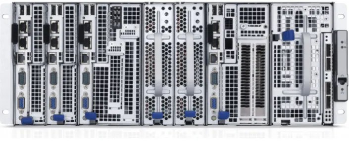
PowerEdge C8000 Series
The PowerEdge C8000 series is Dell’s hyperscale-inspired 4U shared infrastructure server that allows the mixing and matching of compute, storage, and GPU sleds in one chassis. The PowerEdge C8000 chassis holds up to eight single-wide compute PowerEdge C8220 server sleds, up to four double-wide PowerEdge C8220X compute/GPU sleds, or PowerEdge C8000XD storage sleds, or a combination of these, and two power sleds. This design allows the right balance of CPU-to-memory-to-disk ratio and large-scale storage nodes requiring 24 or more hard drives to run big data applications faster. The flexible PowerEdge C8000 can run Master, Slave, and Edge Hadoop nodes and multiple workloads from the same chassis or across racks, allowing for better use of IT resources, lower total cost of ownership over the lifecycle of the server, and more efficient use of space while increasing Hadoop POD compute/storage density and performance.
Figure 3: PowerEdge C8000 Chassis
PowerEdge C8000 feature summary:
• Up to eight independently serviceable PowerEdge C8220 compute sleds, four PowerEdge C8220x compute sleds, or four PowerEdge C8000XD storage sleds in a 4U rack chassis
• Cold aisle service
• Intel® E5-2600 series processors with up to eight cores and support for up to 130W TDP • Up to 256GB of memory with 16 DDR3 slots at 1600MHz per node (512GB RTS+)
PowerEdge C8220 Single Width Compute (SWC)
• Up to 2 x 2.5-inch non-hot-plug hard drives per PowerEdge C8220 compute sled
PowerEdge C8220X Double Width Compute (DWC)
• Up to 12 x 2.5-inch or 4 x 3.5-inch hot-plug hard drives per PowerEdge C8220X compute • Up to 2 x 2.5-inch non-hot-plug hard drives per PowerEdge C8220X compute
• Up to 2 x 2.5-inch hot-plug hard drives per PowerEdge C8220X compute
PowerEdge C8000XD Double Width Storage (DWS)
• Up to 12 x 3.5-inch or 12 x 2.5-inch hot-plug hard drives or 24 x 2.5-inch SSDs per PowerEdge C8000XD storage sled
Cluster Sizing
The minimum configuration supported is eight nodes:
• Crowbar Administration Node • Master Name Node
• Secondary Name Node • High Availability (HA) Node • Edge (or Gateway) Node • Three Data nodes
A minimum configuration can be implemented in three PowerEdge C8000 chassis, if one of the data nodes is installed in the HA chassis.
When using NFS-based HA, the HA node provides a shared NFS mount. In quorum-based HA mode, this node is used as one of the three required quorum nodes, so the node counts remain the same.
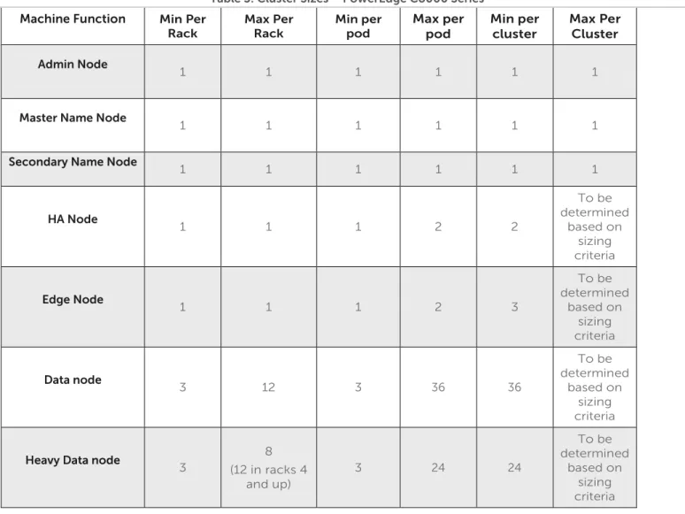
Table 3 shows the minimum and maximum numbers of nodes for each rack, pod, and cluster within this reference architecture.
Table 3: Cluster Sizes – PowerEdge C8000 Series
Machine Function Min Per Rack Max Per Rack Min per pod Max per pod Min per cluster Max Per Cluster Admin Node 1 1 1 1 1 1
Master Name Node
1 1 1 1 1 1
Secondary Name Node 1 1 1 1 1 1
HA Node 1 1 1 2 2 To be determined based on sizing criteria Edge Node 1 1 1 2 3 To be determined based on sizing criteria Data node 3 12 3 36 36 To be determined based on sizing criteria
Heavy Data node
3 8 (12 in racks 4 and up) 3 24 24 To be determined based on sizing criteria
Hardware Configurations
Table 4: Hardware Configurations – PowerEdge C8000 Compute Sleds
Machine Function Active and Secondary Name Node Admin Node,
HA Node Edge Node Data Node Heavy Data Node
Sled 1 PowerEdge C8220X
Processor 2 x E5-2600 (8-core)
RAM
(Minimum) 128 GB 64 GB 64 GB
LOM
2 x 1GbE Network
Controller 2 x Intel X520 10GbE NIC, Dual Port, SFP+,Low Profile Intel X520 10GbE NIC, Dual Port, SFP+,Low Profile DISK
(onboard) None
DISK
(hot-swap) N/A 2 x 2.5-in. 1TB 2 x 2.5-inch 1TB
DISK (side)
6 x 1 TB 2.5-in. SATA 4 x 3 TB 3.5-in. NL SAS 4 x 3 TB 3.5-in. NL SAS DISK (expansion) None 1 x C8220XD 36Tb 2 x C8220XD 72Tb Storage
Controller LSI 2008 (Mezzanine)
Storage
Controller 2 None LSI 9202 (PCI)
RAID
RAID 1 JBOD JBOD
Table 5: Hardware Configurations – PowerEdge C8000 Storage Sleds
Machine Function Active and Secondary Name Node Admin Node, HA
Node Edge Node Data Node
Sled 2
N/A PowerEdge C8220XD
DISK N/A 12 x 3 TB 3.5-in. Nearline SAS (NL-SAS)
Sled 3
N/A PowerEdge C8220XD
DISK
Table 6: Chassis Configuration – PowerEdge C8000 Master Chassis C8220X DWC (Master) C8220X DWC (Admin) Power Power C8220X DWC (Edge) Empty Empty
Refer to Table 30 in Appendix A : for the bill of materials for this chassis.
Table 7: Chassis Configuration – PowerEdge C8000 High Availability Chassis
C8220X DWC (Secondary) C8220X DWC (HA) Power Power C8220X DWC C8220XD DWS
Refer to Table 31 in Appendix A : for the bill of materials for this chassis
Table 8: Chassis Configuration – PowerEdge C8000 Data Nodes
C8220X DWC C8220XD DWS Power Power C8220X DWC C8220XD DWS
Table 9: Chassis Configuration – PowerEdge C8000 ‘Heavy’ Data Nodes C8220XD DWS C8220X DWC Power Power C8220XD DWS C8220XD DWS C8220XD DWS C8220X DWC Power Power C8220XD DWS C8220X DWC C8220XD DWS C8220X DWC Power Power C8220XD DWS C8220XD DWS
Refer to Table 32 and Table 33 in Appendix A : for the bill of materials for these chassis. The Heavy Data node configuration is ordered in groups of three chassis – two ‘heavy’ data node chassis and one data node chassis.
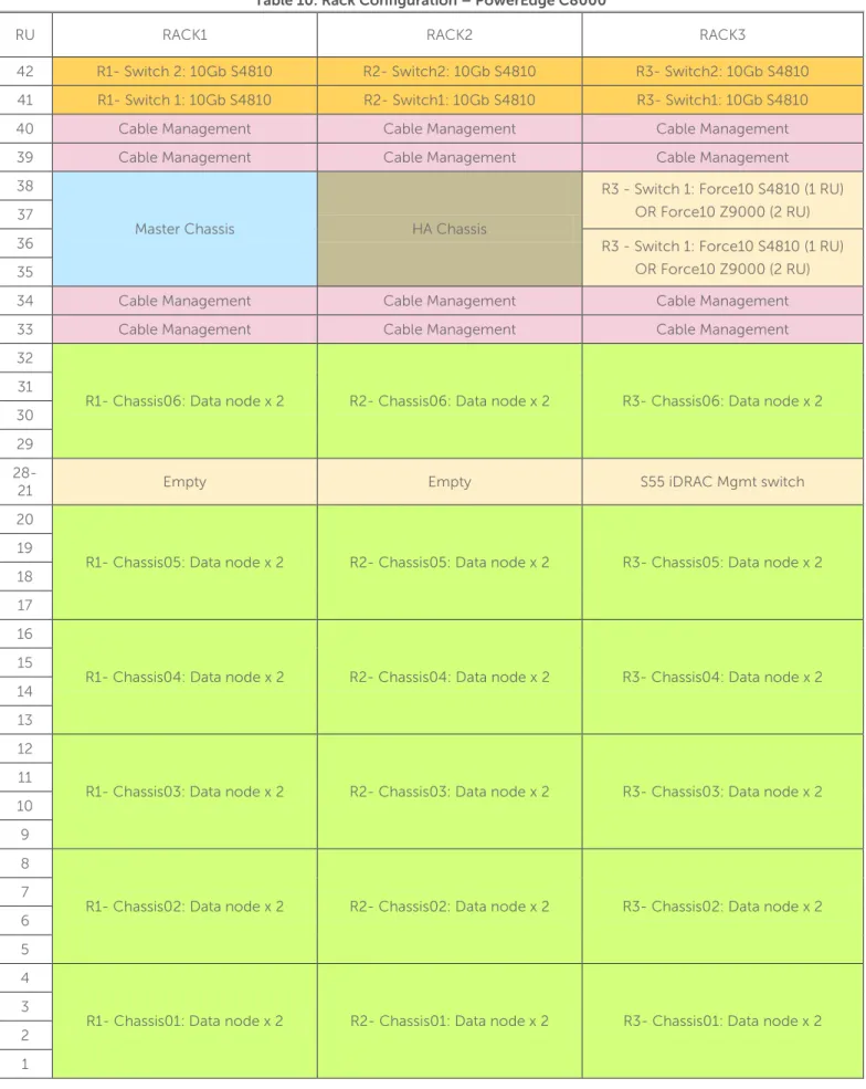
Table 10: Rack Configuration – PowerEdge C8000
RU RACK1 RACK2 RACK3
42 R1- Switch 2: 10Gb S4810 R2- Switch2: 10Gb S4810 R3- Switch2: 10Gb S4810 41 R1- Switch 1: 10Gb S4810 R2- Switch1: 10Gb S4810 R3- Switch1: 10Gb S4810
40 Cable Management Cable Management Cable Management
39 Cable Management Cable Management Cable Management
38
Master Chassis HA Chassis
R3 - Switch 1: Force10 S4810 (1 RU) OR Force10 Z9000 (2 RU) 37
36 R3 - Switch 1: Force10 S4810 (1 RU)
OR Force10 Z9000 (2 RU) 35
34 Cable Management Cable Management Cable Management
33 Cable Management Cable Management Cable Management
32
R1- Chassis06: Data node x 2 R2- Chassis06: Data node x 2 R3- Chassis06: Data node x 2 31
30 29
28-21 Empty Empty S55 iDRAC Mgmt switch
20
R1- Chassis05: Data node x 2 R2- Chassis05: Data node x 2 R3- Chassis05: Data node x 2 19
18 17 16
R1- Chassis04: Data node x 2 R2- Chassis04: Data node x 2 R3- Chassis04: Data node x 2 15
14 13 12
R1- Chassis03: Data node x 2 R2- Chassis03: Data node x 2 R3- Chassis03: Data node x 2 11
10 9 8
R1- Chassis02: Data node x 2 R2- Chassis02: Data node x 2 R3- Chassis02: Data node x 2 7
6 5 4
R1- Chassis01: Data node x 2 R2- Chassis01: Data node x 2 R3- Chassis01: Data node x 2 3
2 1
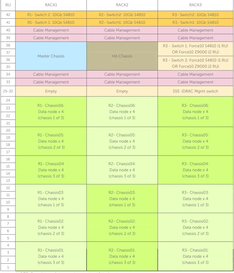
Table 11: Rack Configuration – PowerEdge C8000 ‘Heavy’ nodes
RU RACK1 RACK2 RACK3
42 R1- Switch 2: 10Gb S4810 R2- Switch2: 10Gb S4810 R3- Switch2: 10Gb S4810
41 R1- Switch 1: 10Gb S4810 R2- Switch1: 10Gb S4810 R3- Switch1: 10Gb S4810
40 Cable Management Cable Management Cable Management
39 Cable Management Cable Management Cable Management
38
Master Chassis HA Chassis
R3 - Switch 1: Force10 S4810 (1 RU) OR Force10 Z9000 (2 RU)
37
36 R3 - Switch 2: Force10 S4810 (1 RU)
OR Force10 Z9000 (2 RU)
35
34 Cable Management Cable Management Cable Management
33 Cable Management Cable Management Cable Management
25-32 Empty Empty S55 iDRAC Mgmt switch
24 R1- Chassis06: Data node x 4 (chassis 1 of 3) R2- Chassis06: Data node x 4 (chassis 1 of 3) R3- Chassis06: Data node x 4 (chassis 1 of 3) 23 22 21 20 R1- Chassis05: Data node x 4 (chassis 2 of 3) R2- Chassis05: Data node x 4 (chassis 2 of 3) R3- Chassis05: Data node x 4 (chassis 2 of 3) 19 18 17 16 R1- Chassis04 Data node x 4 (chassis 3 of 3) R2- Chassis04: Data node x 4 (chassis 3 of 3) R3- Chassis04: Data node x 4 (chassis 3 of 3) 15 14 13 12 R1- Chassis03: Data node x 4 (chassis 1 of 3) R2- Chassis03: Data node x 4 (chassis 1 of 3) R3- Chassis03: Data node x 4 (chassis 1 of 3) 11 10 9 8 R1- Chassis02: Data node x 4 (chassis 2 of 3) R2- Chassis02: Data node x 4 (chassis 2 of 3) R3- Chassis02: Data node x 4 (chassis 2 of 3) 7 6 5 4 R1- Chassis01: Data node x 4 (chassis 3 of 3) R2- Chassis01: Data node x 4 (chassis 3 of 3) R3- Chassis01: Data node x 4 (chassis 3 of 3) 3 2 1
Configuration Notes
Appendix A : contains complete bill of materials (BOM) listing for the C8000 server configurations.
Support nodes (Name Node, Crowbar Admin Node, HA Node, Edge Node) are configured with the LSI 2008 controller connected to the front hot-swap drives in the PowerEdge C8220X compute sled.
The two ‘rear’ motherboard drives in the PowerEdge C8220x compute sled are not required for any nodes. Data nodes require one PowerEdge C8220XD sled. Data nodes can alternatively be configured with two PowerEdge C8220XD sleds, referred to as ‘heavy’ data nodes
Data nodes use an LSI 9202 PCI HBA to connect to one or two PowerEdge C8220XD storage sleds. The connection requires one SAS extender cable per external sled.
The reference BOM’s in the appendices are organized by chassis to simplify ordering.
Some configurations may require sled blanks for empty slots; the reference BOMs in the appendices account for this.
The PowerEdge C8000 series is designed for cold-aisle service, with cabling in front of the chassis. Verify that rack configurations are compatible with this configuration.
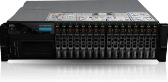
PowerEdge R720(xd) Server
The PowerEdge R720 and R720xd servers are Dell’s 12G PowerEdge mainstream 2S 2U rack servers. They are designed to deliver the most competitive feature set, best performance, and best value. In this generation, Dell offers a large storage footprint, best-in-class I/O capabilities, and more advanced management features. The PowerEdge R720 and R720xd are technically similar except the R720xd has a backplane that can
accommodate more drives (up to 24).
Figure 4: PowerEdge 720xd Server
PowerEdge R720xd feature summary:
• Intel® Romley platform and Intel® Xeon® E5-2600 processors • 1600MHz DDR3
• Network daughter cards for customer choice of LOM speed, fabric, and brand at point of sale • PCIe SSD in a front-accessible, hot-plug format
• Internal GPGPU support
• Intel® Node Manager power management technology • Software RAID
• Platinum efficiency power supplies, common across 600 and 700 series platforms
Cluster Sizing
The minimum configuration supported is eight nodes:
• Crowbar Administration Node • Master Name Node
• Secondary Name Node • High Availability (HA) Node • Edge (or Gateway) Node • Three Data nodes
When using NFS based HA, the HA node provides a shared NFS mount. In quorum-based HA mode, this node is used as one of the three required quorum nodes, so the node counts remain the same.
Table 12 shows the minimum and maximum numbers of nodes for in each rack, pod, and cluster within this reference architecture.
Table 12: Cluster Sizes – PowerEdge R720xd
Machine Function Min Per Rack Max Per Rack Min per pod Max per pod Min per cluster Max Per Cluster Admin Node 1 1 1 1 1 1
Master Name Node
1 1 1 1 1 1
Secondary Name Node 1 1 1 1 1 1
HA Node 1 1 1 2 2 To be determined based on sizing criteria Edge Node 1 1 1 2 3 To be determined based on sizing criteria Data node 3 20 3 60 3 To be determined based on sizing criteria
Hardware Configurations
Table 13: Hardware Configurations – PowerEdge R720xd Machine
Function
Active and Secondary Name
Node
Admin Node, HA Node Edge Node Data node
Platform
PowerEdge R720xd
CPU 2 x E5-2640 (6-core)
RAM
(Minimum) 96 GB 48 GB
LOM 4 x 1GbE
DISK
6 x 600-GB 10K SAS 2.5-inch 24 x 1-TB SATA 7.2K 2.5-inch
Storage
RAID
RAID 10 Single Drive RAID 0
Notes:
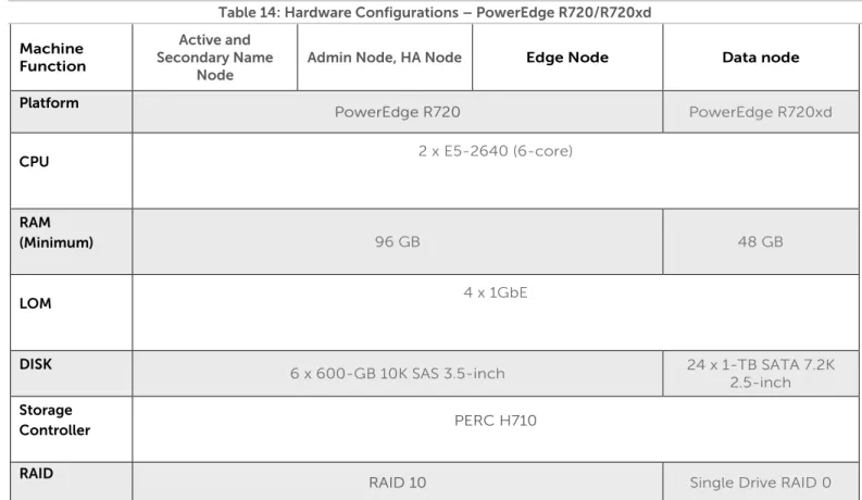
Table 14: Hardware Configurations – PowerEdge R720/R720xd Machine Function Active and Secondary Name Node
Admin Node, HA Node Edge Node Data node
Platform PowerEdge R720 PowerEdge R720xd
CPU 2 x E5-2640 (6-core)
RAM
(Minimum) 96 GB 48 GB
LOM 4 x 1GbE
DISK
6 x 600-GB 10K SAS 3.5-inch 24 x 1-TB SATA 7.2K 2.5-inch
Storage
Controller PERC H710
RAID
RAID 10 Single Drive RAID 0
Notes:
• Be sure to consult your Dell account representative before changing the recommended disk sizes.
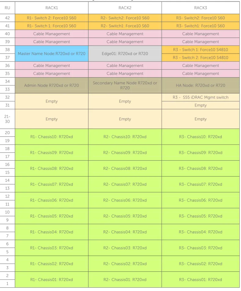
Table 15: Rack Configuration – PowerEdge R720xd (or R720/R720xd)
RU RACK1 RACK2 RACK3
42 R1- Switch 2: Force10 S60 R2- Switch2: Force10 S60 R3- Switch2: Force10 S60 41 R1- Switch 1: Force10 S60 R2- Switch1: Force10 S60 R3- Switch1: Force10 S60
40 Cable Management Cable Management Cable Management
39 Cable Management Cable Management Cable Management
38
Master Name Node:R720xd or R720 Edge01: R720xd or R720 R3 - Switch 1: Force10 S4810
37 R3 - Switch 2: Force10 S4810
36 Cable Management Cable Management Cable Management
35 Cable Management Cable Management Cable Management
34
Admin Node R720xd or R720 Secondary Name Node R720xd or R720 HA Node: R720xd or R720 33
32
Empty Empty R3 - S55 iDRAC Mgmt switch
31 Empty
21-30 Empty Empty Empty
20
R1- Chassis10: R720xd R2- Chassis10: R720xd R3- Chassis10: R720xd 19
18
R1- Chassis09: R720xd R2- Chassis09: R720xd R3- Chassis09: R720xd 17
16
R1- Chassis08: R720xd R2- Chassis08: R720xd R3- Chassis08: R720xd 15
14
R1- Chassis07: R720xd R2- Chassis07: R720xd R3- Chassis07: R720xd 13
12
R1- Chassis06: R720xd R2- Chassis06: R720xd R3- Chassis06: R720xd 11
10
R1- Chassis05: R720xd R2- Chassis05: R720xd R3- Chassis05: R720xd 9
8
R1- Chassis04: R720xd R2- Chassis04: R720xd R3- Chassis04: R720xd 7
6
R1- Chassis03: R720xd R2- Chassis03: R720xd R3- Chassis03: R720xd 5
4
R1- Chassis02: R720xd R2- Chassis02: R720xd R3- Chassis02: R720xd 3
2
R1- Chassis01: R720xd R2- Chassis01: R720xd R3- Chassis01: R720xd 1
Configuration Notes
Appendix B :, Appendix C :, and Appendix D : contain the full bill of materials (BOM) listing for the PowerEdge R720 and R720Xd server configurations.
The R720 and R720xd configurations can be used with 10GbE networking. To use 10GbE networking support, an additional network card is required in each node – refer to the BOM for the details on the supported card.
JBOD versus single disk RAID 0 Configuration
The Hadoop community’s strong advocacy for the “non-RAIDed” drives configuration known as “Just a Bunch of Disks,” or JBOD, has caused some confusion for readers of our reference architecture. We fully endorse this approach but feel a need for clarification because there are multiple valid ways to achieve this configuration. Normally, the optimum disk configuration for Hadoop data nodes is considered to be JBOD mode rather than RAID. This is because HDFS provides its own data replication, eliminating the need for the redundancy
provided by RAID levels 1-6. HDFS also implements efficient round robin parallel I/O across multiple drives, eliminating the need for the parallelism provided by the striping capabilities of RAID 0.
Some drive controllers support only RAID mode, and so can't be used in a plain host bus adapter (HBA) mode for JBOD. For these situations, configuring the controllers as multiple RAID 0 “arrays” allows HDFS to own them as a single drive. In this configuration, the controller is effectively operating just like a standard HBA in JBOD mode, and the RAID 0 and JBOD performance characteristics are comparable. While having a RAID controller adds a minor latency, it is offset by adaptive read-ahead caching.
PowerEdge C6105 Server
The PowerEdge C6105 is Dell’s hyperscale inspired building block for high-performance cluster computing (HPCC), Web 2.0 environments, and cloud builders where performance and power consumption are key. It is purpose-built for scale-out rack deployments, large homogenous cloud/cluster application environments where density is required and the software stack provides platform availability and resiliency.
Figure 5: PowerEdge C6105
PowerEdge C6105 feature summary
• Up to 4 server nodes in 2U • 2 x Opteron 4180
• 12 x DDR3 RDIMM
• 24 x 2.5-inch or 12 x 3.5-inch HDD • 2 x 1GbE Intel 82576
Cluster Sizing
The minimum configuration supported is 8 nodes: • Crowbar Administration Node • Master Name Node
• Secondary Name Node • High Availability (HA) Node • Edge (or Gateway) Node • Three Data nodes
Configurations based on the C6105 use R720 servers for the infrastructure nodes, and C6105 for data nodes. When using NFS based HA, the HA node provides a shared NFS mount. In quorum based HA mode, this node is used as one of the three required quorum nodes, so the node counts remain the same.
Table 16 shows the minimum and maximum numbers of nodes for in each rack, pod, and cluster within this reference architecture.
Table 16: Cluster Sizes—PowerEdge C6105 with PowerEdge R720
Machine Function Min Per Rack Max Per Rack Min per pod Max per pod Min per cluster Max Per Cluster Admin Node 1 1 1 1 1 1
Master Name Node 1 1 1 1 1 1
Secondary Name Node
1 1 1 1 1 1 HA Node 1 1 1 2 3 To be determined based on sizing criteria Edge Node 1 1 1 2 3 To be determined based on sizing criteria Data node 2 PowerEdge C6105 chassis (3 nodes) 10 PowerEdge C6105 chassis (20 nodes) 2 PowerEdge C6105 chassis (3 nodes) 30 chassis (60 nodes) 30 chassis (60 nodes) To be determined based on sizing criteria
Hardware Configurations
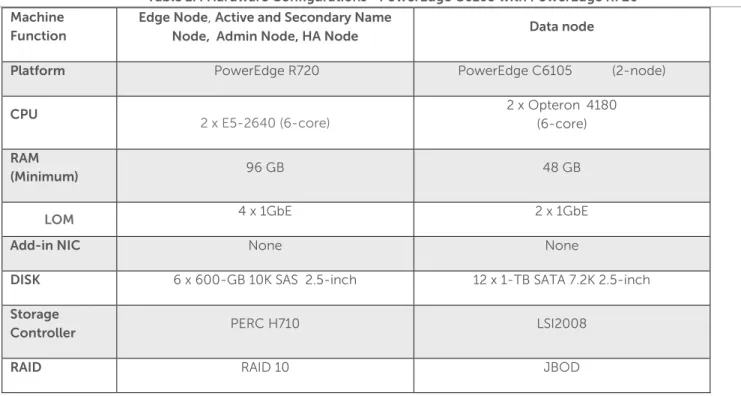
Table 17: Hardware Configurations—PowerEdge C6105 with PowerEdge R720 Machine
Function
Edge Node, Active and Secondary Name
Node, Admin Node, HA Node Data node
Platform PowerEdge R720 PowerEdge C6105 (2-node)
CPU 2 x E5-2640 (6-core) 2 x Opteron 4180 (6-core) RAM (Minimum) 96 GB 48 GB
LOM 4 x 1GbE 2 x 1GbE
Add-in NIC None None
DISK 6 x 600-GB 10K SAS 2.5-inch 12 x 1-TB SATA 7.2K 2.5-inch
Storage
Controller PERC H710 LSI2008
RAID RAID 10 JBOD
Notes:
• Be sure to consult your Dell account representative before changing the recommended disk sizes.
Configuration Notes
Appendix E : contains the full bill of materials (BOM) for the PowerEdge C6105 data node configurations. Appendix C : contains the BOM for the PowerEdge R720 infrastructure nodes that should be used with this configuration.
Table 18: Rack Configuration – PowerEdge C6100
RU RACK1 RACK2 RACK3
42 R1- Switch 2: Force10 S60 R2- Switch2: Force10 S60 R3- Switch2: Force10 S60 41 R1- Switch 1: Force10 S60 R2- Switch1: Force10 S60 R3- Switch1: Force10 S60 40 Cable Management Cable Management Cable Management 39 Cable Management Cable Management Cable Management 38
Master Name Node :R720 Edge01: R720 R3 - Switch 1: Force10 S4810
37 R3 - Switch 2: Force10 S4810
36 Cable Management Cable Management Cable Management 35 Cable Management Cable Management Cable Management 34
Admin: R720 Secondary Name Node R720 HA Node R720 33
32 Empty Empty Cable Management
31 Empty Empty Cable Management
21-30 Empty Empty Empty
20
R1- Chassis10: C6105 (2-Node) R2- Chassis10: C6105 (2-Node) R3- Chassis10: C6105 (2-Node) 19
18
R1- Chassis09: C6105 (2-Node) R2- Chassis09: C6105 (2-Node) R3- Chassis09: C6105 (2-Node) 17
16
R1- Chassis08: C6105 (2-Node) R2- Chassis08: C6105 (2-Node) R3- Chassis08: C6105 (2-Node) 15
14
R1- Chassis07: C6105 (2-Node) R2- Chassis07: C6105 (2-Node) R3- Chassis07: C6105 (2-Node) 13
12
R1- Chassis06: C6105 (2-Node) R2- Chassis06: C6105 (2-Node) R3- Chassis06: C6105 (2-Node) 11
10
R1- Chassis05: C6105 (2-Node) R2- Chassis05: C6105 (2-Node) R3- Chassis05: C6105 (2-Node) 9
8
R1- Chassis04: C6105 (2-Node) R2- Chassis04: C6105 (2-Node) R3- Chassis04: C6105 (2-Node) 7
6
R1- Chassis03: C6105 (2-Node) R2- Chassis03: C6105 (2-Node) R3- Chassis03: C6105 (2-Node) 5
4
R1- Chassis02: C6105 (2-Node) R2- Chassis02: C6105 (2-Node) R3- Chassis02: C6105 (2-Node) 3
2
R1- Chassis01: C6105 (2-Node) R2- Chassis01: C6105 (2-Node) R3- Chassis01: C6105 (2-Node)
Dell | Cloudera Solution Network Architecture
The Dell | Cloudera Solution uses Dell™ Force10™ S60 or Dell™ PowerConnect™ 6248 (optional) Gigabit Ethernet switches as the top-of-rack connectivity to all Hadoop-related nodes. This reference architecture is used to support consistency in rapid deployments through the minimal differences in the network
configuration.
This reference architecture implements at a minimum three distinct, separate VLANs:
• Hadoop Cluster Data LAN—connects the compute node NICs into the fabric used for sharing data and distributing work tasks among compute nodes.
• Hadoop Cluster Management LAN—connects all the iDRAC/BMCs in the cluster nodes. • Hadoop Cluster Edge LAN—connects the cluster to the outside world.
The network consists of three major network infrastructure layouts:
• Data network infrastructure—the data network consists of the server NICs, the top-of-rack (ToR) switches, and the aggregation switches.
• Management network infrastructure—the BMC management network, consisting of iDRAC ports and the
out-of-band management ports of the switches, is aggregated into a 1-RU s55 switch in one of the three racks in the POD. This 1-RU switch in turn can connect to one of the Aggregation or Core switches to create a separate network with a separate VLAN.
• Core network infrastructure—the connectivity of aggregation switches to the core for external connectivity.
Network Components
The data network is primarily composed of the ToR and the aggregation switches. Configurations for 1GbE and 10GbE are included in this reference architecture. The following component blocks make up this network:
Server Nodes
Server connections to the network switches could be one of four possible configurations:
• Active-Active LAG in load-balance bond formation • Active-Backup in failover/failback formation • Active-Active round robin based on gratuitous ARP • Single port
In the first case the connectivity on the switch side must be in a LAG (or port-channel). In cases B and C, we recommend that you do the configuration as a LAG but the ports should still be part of the same layer-2 domain. In some cases all members of the LAG connect to a single ToR switch. In others the LAG splits into two ToR switches. This is an optional setup as Hadoop has redundancy built into the application, and high-availability is not compromised by connecting into a single switch.
The teaming configuration that Dell recommends is balanced-alb (mode = 6). This configuration setting is explained in greater deal in the Dell | Cloudera Solution Deployment Guide. Please contact your sales representative for a copy of the deployment guide. The Dell Crowbar deployment software automatically configures this setting for Hadoop environments.
Access Switch or Top of Rack (ToR)
The servers connect to ToR switches. Typically there are two in each rack. The switches recommended by Dell are the Force10 S60 for 1GbE connectivity and S4810 for 10G servers. The 1GbE option is for PowerEdge C2100 and PowerEdge C6100 servers, while the PowerEdge C8000 requires the 10GbE option. PowerEdge R720 configurations can use 1GbE or 10GbE.
The Force10 S60 ToR switches stack together in the same rack for 1GbE. This is useful in managing the two switches as a single unit and allowing the servers to connect into two different switches for redundancy. The ToR switches each have two expansion slots that can accept a two-port 10G module or a two-port stacking module. This architecture recommends one of each type in the two slots. The 10GbE module would be used to connect into the pod-interconnect switches, one port to each switch, forming a LAG. The stacking module
four 10GbE ports, two from each switch. Each rack connects to the pod-interconnect independently; thereby scaling is easier.
For the 10GbE configuration, the ToR switches are Force10 S4810, and we recommend this pair of switches run a high availability feature called the Virtual Link Trunking (VLT). This feature allows the servers to terminate their LAG interfaces into two different switches instead of one. This allows HA as well as active-active
bandwidth utilization. This feature gives redundancy within the rack if one switch fails or needs maintenance. The uplink to the aggregation pair is 80Gb, using a LAG from each ToR switch. This is achieved using two 40G interfaces in a LAG connecting to the aggregation pair. Therefore, from each rack there is a collective
bandwidth of 160G available.
Each rack is managed as a separate entity from a switching perspective, and ToR switches connect only to the aggregation switches.
Aggregation Switches
For a medium-scale deployment of one to three PODs of 1G servers (12 racks max) the Dell Force10 S4810 is the recommended aggregation switch. It is both 10GbE and 40GbE capable. The 40GbE interfaces on the S4810 could be converted into four 10GbE, thereby converting this switch into 64 10GbE-capable ports. This potentially scales Hadoop deployments into tens of nodes. Hadoop ToR switches connect to aggregate switches via uplinks of 10GbE interfaces from the ToR Force10 S60 to the Force10 S4810.
The recommended architecture uses Virtual Link Trunking (VLT) between the two Force10 S4810 switches in aggregation. This feature enables a multi-chassis LAG from the stacked ToR switches in each rack. The stacks in each rack would divide their links between this pair for switches to achieve the powerful capability of active-active forwarding while using full bandwidth capability, in absence of any requirement for spanning tree. The aggregation switches also run layer-3 from the ToR as layer-2 alone is not a requirement from Hadoop’s perspective. Therefore, for scaling to large deployments, layer-3 routing is a good option. Running 40GbE Ethernet switches like the Dell™ Force10™ Z9000 in aggregation can achieve a scale of up to hundreds of 1G deployed nodes.
For the 10G server deployment, depending on the scale at which the PODs are planned and depending on the how much future scale is required, we recommend the Force10 S4810 for aggregation for smaller scale and the Force10 Z9000 for larger deployment. The Force10 Z9000 is a 32-port, 40G high-capacity switch. It can aggregate up to 15 racks of high-density PowerEdge C8000 servers. The rack-to-rack bandwidth needed in Hadoop would be most suitably handled by a 40G-capable, non-blocking switch. The Force10 Z9000 can provide a cumulative bandwidth of 1.5TB of throughput at line-rate traffic from every port.
Core
The aggregation layer could itself be the network core in many cases but where it’s not, it would connect to a larger core, which is represented by the cloud in Figure 7. Details on this topic are beyond the scope of this document.
Layer-2 and Layer-3
The layer-2 and layer-3 boundaries are separated at either the ToR or the aggregation layer. Either of the options is equally viable. The colors blue and red in Figure 7 represent the layer-2 and layer-3 boundaries. This document uses layer-2 as the reference up to the aggregation layer. That is why VLT is used on the
aggregation switches.
Single Rack Configuration
Figure 6 shows the single rack equipment. Dell recommends using Force10 S60 ToR switches in the rack. Each rack could have a maximum of 20 servers in some configurations, while a dense packing of sleds in the C-series server chassis can hold even more. Each rack has two ToR Force10 S60 switches that are stacked, and this stack connects to the two Force10 S4810 aggregation switches. The Force10 S60 stack offers a single switch view to the servers. Each Data node can have up to four 1G NIC ports. It forms a LAG of two ports with one port on each switch in the stack. The LAG of 2GbE offers a switch redundancy within the rack and enables high availability.
Table 19: Single Rack Network Equipment
Total Racks 1 (6-20 nodes)
Top-of-rack switch 2 Force10 S60 (2 per rack)
Aggregation switch Not needed for a single rack
Server 2RU PowerEdge R720/R720xd/C2100/C6100
Over-subscription at ToR 1:1
Modules in each ToR 1x 12-2port Stacking, 1x 10G -2 port uplink
Figure 6 Single Rack Networking Equipment
Figure 7 shows the Force10 S4810 switch aggregating the pods to enable inter-rack traffic and the management network. There are two separate VLANs for data and management. All port-channels on the Force10 S4810 and ToR are tagged in these two VLANs.
Figure 7 Multi-rack networking equipment
Table 20: Multi Rack Network Equipment
Total racks 3 (15-20 nodes per rack)
Top-of-rack switch 6 Force10 S60 (2 per rack)
Pod-interconnect switch 2 Force10 S4810
Server 2RU PowerEdge R720/R720xd/C2100
Over-subscription at ToR 1:1
Modules in each ToR 1x 12-2port Stacking, 1x 10G -2 port uplink
Multi-rack configuration for 10GbE with Force10 S4810
In this reference architecture we define a 10G solution with the PowerEdge C8000 and R720X servers.
Hadoop applications are increasingly being deployed on 10GbE servers for the scale and price advantages they bring. That brings about an enormous economy of scale in the usage of hardware. That in turn needs 10GbE switches in the racks. This can be achieved using the Force10 S4810 as a top-of-rack switch and the option of using Force10 S4810 or Z9000, the 10G/40G high-density switch in the aggregation. The scale that is achieved by that configuration can grow into thousands of nodes using a CLOS architecture, which was used in the 600-node 1GbE solution above. Running 40GbE switches like the Force10 Z9000 in aggregation can achieve a scale of hundreds of nodes using high-density data center class switches.
Figure 8: Multi-Rack View for 10G Servers Using Force10 s4810 Switches
In Figure 8 we see that each rack with a pair of switches aggregates into the pair of Force10 S4810 switches. This connection could be based on layer-2, if the aggregation runs on the VLT feature. Alternately it could run on layer-3 point-to-point routing using some routing protocol such as OSPF. In both cases all links utilize the full bandwidth on all links due to load-balancing. The first scenario creates a complete layer-2 domain between all racks in the cluster.
The Force10 s4810-based aggregation design is preferred for lower cost and medium scalability. This design can handle up to six racks or two PODs. The way this connectivity works is that the ToR Force10 s4810 uplinks using its 40G interface in quad-mode where each 40G interface runs as 4x 10G. The figure below shows the cables needed for this design. If using a passive copper break-out cable there is no need to any QSFP+ or SFP+ other than the cable as these are built into the copper twin-ax cable. This makes the arrangement cost less than the fiber option where there is a need for a QSFP+ optic and four SFP+ optics plus the break-out fiber. The benefit of the fiber option is the longer reach achieved with it compared to twin-ax, which is limited to 5 meters.
Multi-rack Configuration for 10GbE Using Force10 Z9000 Switches
For a scale-out version of the deployment that is looking to expand its Hadoop environment into a larger setup or needs the Hadoop cluster co-located with other applications in different racks, the recommended option is the Force10 Z9000 core switch. The Force10 Z9000 does not need to connect into any other higher-tier core switches as the capacity is enough for a data center with hundreds of servers.
Figure 9: Multi-Rack View for 10G Servers Using Force10 Z9000 (based on Layer-3)
Figure 9 shows a routed version where each s4810 in the rack has a layer-3 connection to the core switch. LAG is not required for this option as each connection could be a point-to-point routed link. Optionally each switch could form a Layer-2 LAG as shown in Figure 10. This assumes that the Z9000 pair in the aggregation forms a VLT pair for HA. Now we have 2 tiers of VLT, one forming at the ToR for servers and another at the aggregation for the top of rack switches. Each option has its own merits and equally recommended depending how the user sees it fit the larger network in the Data Center.
Figure 10: Multi-Rack View Using Force10 Z9000 Switches (Based on Layer-2)
In Figure 10 we see an example of a CLOS fabric that grows horizontally. This technique of network fabric deployment has been used by some of the largest Web 2.0 companies, whose businesses range from social media to public cloud in their data centers. Some of the largest recent Hadoop deployments also use this new approach to networking. Dell Data Center Solutions has hands-on experience in building Hadoop and Big Data analytics farms while Dell Force10 is a trusted vendor in the field of networking. Dell can help an enterprise solve its Big Data needs with a scalable end-to-end solution.
Management Network
The management network of all the servers and switches is aggregated into a Dell™ Force10™ S55 switch that is located in rack-3 of the POD. It uplinks on a 10G link to the aggregation switches or the core directly
wherever the split for out-of-band is required.
Dell Open Switch Solution
In addition to the Dell switch-based reference architecture, Dell provides an open standard that allows you to choose other brands and configurations of switches for your Hadoop environment. The following list of requirements will enable other brands of switches to properly operate with the tools and configurations in the Dell Hadoop Reference Architecture:
• Support for IEEE 802.1Q VLAN traffic and port tagging
• Ability to provide a minimum of 170 Gigabit Ethernet ports in a non-blocking configuration within VLAN 100
o Configuration can be a single switch or a combination of stacked switches to meet the additional requirements
• The ability to create link aggregation groups (LAGs) with a minimum of two physical links in each LAG
• If multiple switches are stacked:
o The ability to create a LAG across stacked switches
o Full-bisection bandwidth
o Support for VLANs to be available across all switches in the stack
• The ability to provide a minimum 65 10/100 Ethernet ports on the untagged VLAN • 250,000 packets-per-second capability per switch
• The ability to provide 12 10Gb ports for redundant uplinks contained in VLAN 10 • A managed switch that supports SSH and serial line configuration
IPv6 Capabilities
At this time, the Dell | Cloudera Solution does not support or allow for the use of IPv6 for network
connectivity. All deployments are configured by Crowbar based on IPv4, with IPv6 explicitly disabled on all nodes within the Hadoop environment.
Network Connectivity
The network interconnects between various hardware components of the Hadoop solution are depicted in Figure 11 and Figure 12. For more information, please see the deployment guide.
Figure 11: Dell | Cloudera Compute PowerEdge R720xd Node Network Interconnects
Dell | Cloudera Solution Software Architecture
Table 21: Dell | Cloudera Solution Support Matrix
RA Version OS Version Hadoop Version Available Support Supported JVM
2.1 Red Hat Enterprise Linux 6.2 CDH 4.1 Cloudera Manager 4.1
Dell Hardware support Cloudera Hadoop
support Red Hat Linux support
Sun Oracle JVM
2.1 CentOS 6.2 CDH 4.1
Cloudera Manager 4.1 Dell Hardware support Sun Oracle JVM
Linux File System Configuration Definition
Dell and Cloudera recommend and support the use of ext4 for all HDFS disks.
Disk Partitioning Recommendation for the Name Node
All disk configuration parameters are documented in the Dell | Cloudera Solution Deployment Guide, as well as Linux Kickstart scripts for proper configuration at the time of operating system installation.
Configuration Parameters: Recommended Values
Table 22: HDFS parameters
Property Description Value
dfs.block.size Lower value offers parallelism 134217728 (128Mb)
dfs.name.dir Comma-separated list of folders (no space) where a SlaveNode stores its blocks /mnt/hdfs/hdfs01/meta1
dfs.datanode.handler.count Number of handlers dedicated to serve data block requests in Hadoop SlaveNodes
16
(Start 2 x CORE_COUNT in each SlaveNode )
dfs.namenode.handler.count More Master Node server threads to handle RPCs from large number of SlaveNodes
Start with 10, increase large clusters (Higher count will drive higher CPU,
RAM, and network utilization)
dfs.datanode.du.reserved The amount of space on each storage volume which HDFS should not use 10M
dfs.replication Data replication factor; default is 3 3 (default)
fs.trash.interval Time interval between HDFS space
reclaiming 1440 (minutes)
dfs.permissions true (default)
dfs.datanode.handler.count 8
dfs.data.dir Hadoop Data Node Location
/mnt/hdfs/hdfs01/data1/hdfs comma-separated through
Table 23: mapred parameters
Table 24: default environment
Property Description Value
SCAN_IPC_CACHE_LIMIT
Number of rows cached in search engine for each scanner next call over the wire; it reduces the network round trip by 300 times caching 300 rows in
each trip
100
LOCAL_JOB_HANDLER_COUNT
Number of parallel queries executed at one go; query requests above this limit
are queued up
30
Table 25: hadoop-env.sh
Property Description Value
java.net.preferIPv4Stack true
HADOOP_*_OPTS -Xmx2048m
Table 26: /etc/fstab
Property Description Value
mapred.child.java.opts Larger heap-size for child JVMs of maps/reduces. -Xmx1024M
mapred.job.tracker Hostname or IP address and port of the
JobTracker namenode:8021
mapred.job.tracker.handler.count
More JobTracker server threads to handle RPCs from large number of
TaskTrackers
Start with 32, increase large clusters (Higher count will drive higher CPU,
RAM, and network utilization)
mapred.reduce.tasks The number of Reduce tasks per job Set to a prime close to the number of available hosts
mapred.local.dir
Comma-separated list of folders (no space) where a TaskTracker stores
runtime information /mnt/hdfs/hdfs01/data1/mapred comma-separated through /mnt/hdfs/hdfs01/dataN/mapred mapred.tasktracker.map.tasks. maximum
Maximum number of map tasks to run
on the node 2 + (2/3) * number of cores per node mapred.tasktracker.reduce.tasks.
maximum Maximum number of reduce tasks to run per node 2 + (1/3) * number of cores per node
mapred.child.ulimit 2097152 mapred.map.tasks.speculative. execution FALSE mapred.reduce.tasks.speculative. execution FALSE mapred.job.reuse.jvm.num.tasks 1
File system mount options data=writeback,nodiratime, noatime
Table 27: hdfs (core-site)
Property Description Value
io.file.buffer.size
The size of buffer for use in sequence files; the size of this buffer should probably be a multiple of hardware page size (4096 on Intel x86), and it determines how much data is buffered
during read and write operations
65536 (64Kb)
fs.default.name
The name of the default file system; a URI whose scheme and authority
determine the file system implementation
hdfs://namenode:8020
fs.checkpoint.dir
Comma-separated list of directories on the local file system of the Secondary
Master Node where its checkpoint images are stored
TBD
io.sort.factor 80
Io.sort.mb 512
Table 28: /etc/security/limits.conf
Property Description Value
mapred – nofile 32768
hdfs –nofile 32768
Dell | Cloudera Solution Cloudera Enterprise Software
The Dell | Cloudera Solution is based on Cloudera Enterprise, which includes Cloudera’s distribution for Hadoop (CDH) 4.1 and Cloudera Manager.
Deployment Integration
The Dell | Cloudera Solution v2.1 uses Crowbar to deploy the infrastructure: BIOS and RAID configurations, and the base operating system. Cloudera Manager is used to deploy the rest of the Hadoop software stack. Cloudera Manager installs the core Hadoop components (HDFS and Map Reduce) and some of the ecosystem components. Pig, Hive, and Sqoop ecosystem components have to be installed via Crowbar barclamps. Please refer to the Crowbar Administration User Guide for details on how to deploy Cloudera Manager and the ecosystem services supported by the solution.
Cloudera Manager
Cloudera Manager deploys and centrally operates a complete Hadoop stack. The application automates the installation process, thereby reducing deployment time from weeks to minutes. These are the functional characteristics of Cloudera Manager:
• Provides a cluster-wide, real-time view of the services running and the status of their hosts • Provides a single, central place to enact configuration changes across the cluster
• Incorporates a full range of reporting and diagnostic tools to help optimize cluster performance and utilization
• Provides full lifecycle management for Hadoop deployments
• Enables the configuration of server roles and services across the cluster • Provides the interface to gracefully start, stop, and restart services as needed
Cloudera Manager Editions
There are two editions of Cloudera Manager: the Free Edition and the Enterprise Edition. A license is not needed to use the Free Edition but the number of hosts supported is limited to 50. The Enterprise Edition supports an unlimited number of hosts, requires a license, and provides service monitoring and additional management features that are not included in the Free Edition.
Table 29: Differences between Cloudera Manager Free Edition and Enterprise Edition
Cloudera Manager Editions Free Enterprise
Maximum Number of Nodes Supported 50 Unlimited
Automated Deployment & Hadoop Readiness Checks Comprehensive API
Service & Configuration Management
Deploy & Configure HDFS, MapReduce, Flume, HBase, Hue, Impala*, Oozie & Zookeeper Services Configure High Availability & Federation
Automated Configuration
Client Configuration Management Audit Trail
Add/Delete/Stop/(Re)Start/Decommission Role Instances Configuration Versioning & History
Service Monitoring & Management
Monitor HDFS, MapReduce, Hue, Flume, Hue, Oozie & Zookeeper (Cloudera Enterprise Core)
Monitor Impala* (Cloudera Enterprise RTQ) Proactive Health Checks
Status & Health Summary
Heatmaps/Performance Monitoring Host Monitoring Security LDAP Authentication Kerberos Configuration Multi-Cluster Management Intelligent Log Management Events Management & Alerts Activity Monitoring
Operational Reporting
File Browser & Quota Management Global Time Control
Support Integration
Maintenance Mode
http://www.cloudera.com/content/cloudera/en/products/cloudera-manager.html
Cloudera Support
As the use of Hadoop grows and an increasing number of groups and applications move into production, your Hadoop users will expect greater levels of performance and consistency. Cloudera’s proactive production-level support gives your administrators the expertise and responsiveness they need.
Cloudera Support includes: Flexible Support Windows
• Choose 8×5 or 24×7 to meet SLA requirements. Configuration Checks
• Verify that your Hadoop cluster is fine-tuned for your environment. Escalation and Issue Resolution
• Resolve support cases with maximum efficiency. Comprehensive Knowledge Base
• Expand your Hadoop knowledge with hundreds of articles and tech notes. Support for Certified Integration
• Connect your Hadoop cluster to your existing data analysis tools. Proactive Notification
• Stay up-to-speed on new developments and events.
With Cloudera Enterprise, you can leverage your existing team’s experience and Cloudera’s expertise to put your Hadoop system into effective operation. Built-in predictive capabilities anticipate shifts in the Hadoop infrastructure to support reliable function.
• Simplifying and accelerating Hadoop deployment
• Reducing the costs and risks of adopting Hadoop in production • Reliably operating Hadoop in production with repeatable success • Applying SLAs to Hadoop
• Increasing control over Hadoop cluster provisioning and management
HDFS Highly Available Name Nodes
The Dell | Cloudera Solution v2.1 includes CDH 4.1 and Cloudera Manager 4.1, which feature Highly Available Name Nodes for HDFS.
There are two options for name node high availability: • Active/Passive using Shared Storage • Quorum-based
Only one of these can be used in a single cluster. Quorum-based high availability is recommended for new installations. Additional information about the high availability features of CDH4 can be found in the CDH4 High Availability Guide ( http://ccp.cloudera.com/display/CDH4DOC/CDH4+High+Availability+Guide )
Active/Passive HA using Shared Storage
This configuration will set up name nodes in an Active/Passive Configuration. The Active Name Node
(formerly Master Name Node) is responsible for all client operations in the cluster, while the Standby (formerly Secondary Name Node) is simply acting as a slave, maintaining enough shared state via the filer to provide a fast failover if necessary. In order for the Standby node to keep its state synchronized with the Active node, the active/passive implementation requires that the two nodes both have access to a directory on a shared storage device, in this case an NFS mount from the HA Node.
(http://www.cloudera.com/blog/2012/03/high-availability-for-the-hadoop-distributed-file-system-hdfs/).
Quorum-based HA
In Quorum-based HA, the Standby node keeps its state synchronized with the Active node by communicating with a group of separate daemons called JournalNodes. When any namespace modification is performed by the Active node, it durably logs a record of the modification to a majority of these JournalNodes. The Standby node is capable of reading the edits from the JournalNodes, and is constantly watching them for changes to the edit log. As the Standby Node sees the edits, it applies them to its own namespace. In the event of a failover, the Standby will ensure that it has read all of the edits from the JournalNodes before promoting itself to the Active state. This ensures that the namespace state is fully synchronized before a failover occurs. There should be an odd number (and at least three) JournalNode daemons, since edit log modifications must be written to a majority of JournalNodes. The JournalNode daemons run on the Master, Secondary, and HA nodes in this reference architecture.
Figure 13: HDFS with Highly Available Name Node
Dell | Cloudera Solution Deployment Methodology
Site Preparation Needed for the Deployment
The heating, ventilation, air conditioning (HVAC) and power requirements for deployment can be estimated using the Dell Energy Smart Solution Advisor at:
http://www.dell.com/content/topics/topic.aspx/global/products/pedge/topics/en/config_calculator?c=us&cs=555&l=en&s =biz
Using this tool, you can plan the needs for your solution, order the correct PDUs, and have the proper HVAC ready for the installation.
Detailed deployment instructions are documented in the Dell | Cloudera Solution Deployment Guide.
Dell | Cloudera Solution Hardware Monitoring and Alerting
To automate the alert and response to unexpected events and failures within the Dell | Cloudera Solution, the software stack includes Nagios and Ganglia. The Dell | Cloudera Solution includes capabilities for three primary components of the monitoring environment:
Monitoring of cluster activities—The Dell | Cloudera Solution utilizes Nagios to monitor the cluster, including hardware, software, and users. The Nagios deployment as part of the Dell | Cloudera Solution will keep historical information regarding system availability, maintenance, and failure events.
• Alerts on unexpected events—The Dell | Cloudera Solution utilizes Nagios to alert system operations staff to events that occur that deviate from normal operation, if the administrator has designated them for
notification.
• Debugging of cluster runtime operations— The Dell | Cloudera Solution utilizes Cloudera Enterprise to provide the users and administrators of the Hadoop environment with the necessary tools for tracking, debugging, and monitoring job performance and characteristics.
The Dell | Cloudera Solution is designed to include the necessary components to monitor and respond to events in your Hadoop environment. It is flexible enough to allow integration with existing operations management frameworks in your environment.