A System Design for Surveillance Systems Protecting
Critical Infrastructures
Erland Jungert
1, Niklas Hallberg
1,2, Niclas Wadströmer
11FOI (Swedish Defence Research Agency)
Box 1165, SE-581 11 Linköping, Sweden {jungert, nikha, niclas.wadstromer}@foi.se
2School of Computer Science and Communication KTH Royal Institute of Technology
SE-100 44 Stockholm, Sweden
Abstract---Critical infrastructures are attractive targets for attacks by intruders with different hostile aims. Modern information and sensor technology provides abilities to detect such attacks. The objective of this work is to outline a system design for surveillance systems aimed at protection of critical infrastructures, with the focus on early threat detection at the perimeters of critical facilities. The outline of the system design is based on an assessment of stakeholder needs. The needs were identified from interviews with domain experts and system operators. The system design of the surveillance system and the user requirements in terms of capabilities were then determined. The result consists of the systems design for surveillance systems, comprising the systems capabilities, the systems structure, and the systems process.The outcome of the work will have an impact on the implementation of the surveillance systems with respect to the sensors utilized, the sensor data algorithms and the fusion techniques.
Keywords: security systems, surveillance systems, critical infrastructure, user requirements,
I. INTRODUCTION
In recent times, the risk for critical infrastructures to be subject to attacks from various groups of terrorists or criminals has become increasingly high and therefore they must be protected. To accomplish sufficient surveillance, modern information technology could be used. Such surveillance systems need to be based on modern sensors and sensor systems with advanced sensor-data analysis and data fusion. However, to accomplish systems of high quality, they must be based on the stakeholders needs, so that needed capabilities can be provided that support the system operators in their work to handle upcoming events and incidents enforced to the facilities to be protected from attacks [1]. Hence, to accomplish such surveillance systems it is essential to put a sufficient amount of resources on the early stages of the development, which is to identify the stakeholder needs and to define the users requirements in terms of system capabilities. To enhance the realization of such systems they should be based on an adequate system design. Thereby, the probability to get useful systems that provide the means to support
handling of incidents and crisis management will increase and help to avoid or at least minimize the consequences of attacks on critical infrastructure facilities. The approach taken for determination of the system design is based on the assessment of stakeholder needs through a series of interviews with a number of especially appointed domain experts and security personnel.
This work has been carried out as a part of the EU project, The Privacy Preserving Perimeter Protection Project (P5). The objective of the project is to demonstrate an intelligent perimeter surveillance system that will operate in all weather and light conditions and with privacy preserving properties. The system will monitor a part of the area just outside the boundary of critical infrastructure facilities and, thereby, provide early warnings to detected terrestrial and airborne threats. The system should have a low false alarm rate, e.g. due to animals and other innocuous events, combined with high level of threat detection sensitivity and privacy standards will be central ambitions of the project.
The objective of the work described here is to outline a systems design for surveillance systems aimed at protection of critical infrastructures. In particular, the surveillance system should be able to support the security staff at the facility to respond to attacks from intruders at an early stage and thus the protection and surveillance of the perimeter of the facilities will be in focus to make it possible to give early warnings of attacks. Thus the overall objective of this part of the project is to identify a systems design including user requirements in terms of capabilities. The system should thus be able to warn for threats carried out by different types of objects, (persons or vehicles etc.). Eventually, these capabilities of warnings should be realized by state of the art sensor solutions. To determine what sensors to be used and the methods for sensor-data analysis and fusion is, however, outside the scope of this part of the P5 project.
II. PHYSICAL CONTEXT
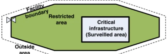
The physical context in which surveillance systems of critical infrastructures operate is varying from facility to facility; especially with respect to the perimeter, which also differ with respect to the type of infrastructure that should be protected. Generally, the critical infrastructure facility can be described as containing a central complex, i.e. the surveilled area of the critical infrastructure with one or several buildings or installations as illustrated in Fig.1. The area surrounding the survelled area makes up the perimeter of the facility that may differ in width with respect to its extension. Thus, the perimeter can be defined as illustrated in Fig. 1 where the perimeter is made up by the Restricted area, the Facility boundary, a strip of the outside area, and the airspace above the facility. In some cases, there is no restricted area and the boundary of the facility coincides with the boundary of the Surveilled area. The outside strip may also vary from facility to facility depending on its context. Further, the terrain type at different facilities, differ as well and the surveillance system must be able to adapt to such differences. Critical infrastructure (Surveilled area) Restricted area Outside area Facility boundary
Figure 1. An illustration of an extended perimeter surrounding a critical infrastructure facility.
III. METHODS
The work was carried out as two main activities: a needs assessment activity and an outline of the design of the surveillance systems.
A. Needs assessment
The needs assessment was performed in six steps. The initial step was to determine who the stakeholders are, which of them should be given the opportunity to influence the development of the system, and how their statements should be collected. The work was carried out during a workshop, involving the project management, in which different categories of stakeholders were identified, such as systems operators, business managers, and security managers. Thus, it was decided which categories of stakeholders that should be provided the opportunity to influence the design of the system. The second step was to capture the stakeholders’ statements. The respondents were selected as good representatives of the selected stakeholder categories. Interview questions that focus on the specific problems subject to the studies were developed. Each interview was carried out by two persons; one that asked the questions and another
responsible for recording the answers through note taking. The third step of the needs assessment was to interpret the collected statements to determine the actual needs. When asking stakeholders about what needs they have, they will use descriptions of, e.g., problematic situations that they have experienced and technical solutions that they believe can be useful to them [2]. The Voice of the customer table (VCT) was used for analyzing statements to reveal the actual needs [1][3]. The outcome from this step was a large set of unstructured and unsorted needs.
The fourth step was to thoroughly analyse the identified needs, to unify the formulation of the needs and, thereby, identify and discard duplicates of needs. Further, the analysis also included to determine if any needs had been left out, and if appropriate add the missing ones. To accomplish this and due to the amount of needs it is likely necessary to categorize the needs. This step was performed by using affinity diagrams and hierarchy diagrams [3]. The fifth step is to validate the needs. This was carried out in a workshop with stakeholder representatives. During the workshop the identified needs were presented to the stakeholders’ representatives; based on their comments inaccuracies were corrected. The sixth step was to prioritize the needs in terms of stakeholder value.
During a workshop, the stakeholders’
representatives were asked to prioritize, on a scale from 0 to 3, the identified needs based on how important they considered the needs to be; taking into account the scope of the project. In this case 3 means the highest importance and 0 not important. The highest prioritized needs, 3 and 2, were established as the needs that should constitute the foundation for the determination of the capabilities.
B. Outline of the system design
The outline of the system design was carried out in three steps as definition of (1) the systems capabilities, (2) the systems structure, and (3) the systems process. The initial step, to define the systems capabilities was based on the needs with the highest priorities. The capabilities were compiled and elaborated to a coherent set of capabilities, documented in a hierarchical diagram [3]. The validation of the capabilities was performed during several workshops where the developers present the capabilities to the stakeholder representatives. The provided comments and suggestions are analyzed and appropriately incorporated in the set of capabilities. The second step was to define the structure of the systems, i.e., systems components that together provide the defined capabilities. The third step was to define systems process. That is
outlining how the systems accomplish the capabilities, as activity diagrams [3].
After the first version of the system design was completed, validation of the design was performed with stakeholder representatives and technical experts. The latter were experts on surveillance techniques.
IV. SYSTEM CAPABILITIES
The outcome of this study is a system design for surveillance systems for protection of critical infrastructures. The design is based on the systems capabilities, the systems structure, and its process.
A. Outline of the system design
The systems capability structure is hierarchical and will thus include sets of subordinate capabilities and eventual a number of leaf capabilities. Leaf capabilities with attachments to the Sensor data analysis and fusion modules are either of the type
Track (an entity of an event), Detect and Watch
(entities). Detect and Watch are concerned with the detection of objects deviating from normal inside the boundary of the facility respectively outside whereas Track is concerned with tracking of the deviating objects. Watch is similar to Detect but since different legislation is applied to the outside area (in most countries), sensor types that directly can identify individuals are not allowed on the outside due to privacy considerations that must be followed and for this reason Watch is introduced.
The general interpretation of the capabilities is that a certain capability is not enabled until all its subordinate capabilities have been enabled or when a leaf node has been supplied with relevant event related information or in some other way terminated.
The ultimate capability for the protection and the surveillance of critical infrastructures in this work is
Handle facility protection. This capability has four subordinate capabilities Handle surveillance, Handle deviation, Handle incident and Handle user interactions (Fig. 2).
Handle facility protection
Handle incident Handle user interactions Handle
surveilance Handle deviation
Figure 2. The two top levels of the capability structure,
The capability Handle surveillance is concerned with surveillance of the perimeter of the facility, which on the next lower level is utilized by four capabilities: Surveil Restricted area, Surveil Boundary fence, Surveil Airspace, and Watch Outside area (Fig. 3). These capabilities are aimed at the surveillance of the facility perimeter. Furthermore, the capability
Handle surveillance relates to aspects like: the system
should be able to operate e.g. without interruption, during all weather conditions and with respect to privacy considerations. Handle surveillance Surveil Restricted area Surveil at different states Surveil with respect to given constraints Watch Outside area Surveil Boundary
fence Surveil Airspace Surveil with
respect to the given context
Figure 3. The Handle surveillance branch of the capability
structure.
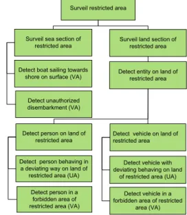
An illustration to the deeper levels of the four perimeter surveillance oriented capabilities in Fig. 3 can be seen in Fig. 4, which shows how they are divided further into surveillance of the land and the sea areas and on the lowest level the detection of various types of events requested to release an alarm; this is indicated with either one of the alarm types: verified alarm (VA) or unverified alarm (UA) (section IV D). Thus, a Detect capability for protection of the Restricted area is formulated as
Detect person behaving in a deviating way on land of restricted area (UA), which indicates that the capability determined to detect a person behaving in a deviating way and that the alarm in this case is unverified and consequently needs to be verified in some way, e.g., guards can be sent out by the operator to determine what kind of event that has occurred.
Detect entity on land of restricted area
Detect vehicle in a forbidden area of restricted
area (VA) Detect boat sailing towards
shore on surface (VA) Surveil sea section of
restricted area
Surveil land section of restricted area Surveil restricted area
Detect vehicle on land of restricted area Detect unauthorized
disembarkment (VA)
Detect vehicle with deviating behaving on land
of restricted area (UA) Detect person on land of
restricted area
Detect person in a forbidden area of restricted area (VA) Detect person behaving in a deviating way on land of
restricted area (UA)
Figure 4. The capabilities for surveillance of the facility perimeter.
The second capability, on the second level, is the
Handle deviation that has to be enabled once a deviation has been determined (Fig. 5). These capabilities are concerned with the handling of the type of alarm that has been released but also to the analysis of the occurred deviation type that eventually should be reported.
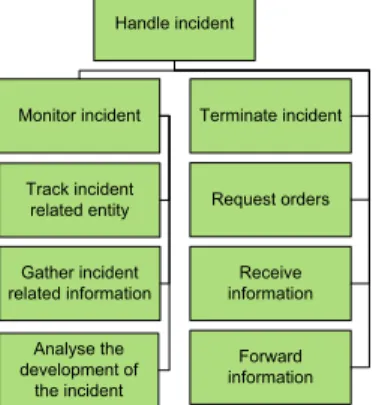
The third capability, Handle incident (Fig. 6), is enabled when an incident has been determined, by a verified alarm, and is concerned with the monitoring of the incident, that is, to track incident related objects, to gather, analyse and store various kinds of incident related information but also to request orders from and to forward information to participating persons in the crisis management organization. Eventually, the incident will be terminated.
Handle deviation Handle unverified alarm Report deviation Analyse deviation Handle verified alarm
Figure 5. The main part of the Handle deviation capability structure.
The fourth and final capability at the top level, i.e.,
Handle user activities and support (Fig. 7). This
capability is aimed at directly support the operators to control sensors, basically of visual type, and to gather information from them. Further, information gathered by the surveillance system should also be handled, stored and aggregated in such a way that a situational picture can be built up. The situational picture must also be possible to adapt to the needs of the operator, e.g., by zooming and panning to follow the events going on during an incident. Among other things, the situational picture will include information of deviating objects such as detected deviations, objects locations and tracks and alarm related information.
Handle incident
Request orders Monitor incident
Gather incident
related information informationReceive Track incident related entity Forward information Terminate incident Analyse the development of the incident
Figure 6. The Handle incident capability structure.
B. System structure
The main components of the system structure are: the User interface module, the Command & control module and the Sensor system module (Fig. 8). Inside
the Command & control module there is the User support module that handles the surveillance processes and on its upside it supports the user interface; this means that it is serving the operator of the surveillance system. At the down side, the surveillance processes are served by the Sensor data analysis & fusion module. The sensor system
delivers information about detected objects and tracks from these objects.
Handle user interactions
Adapt & present current operational picture Gather operational information Control sensors Manual gathering (VA) Automatic gathering (VA) Manual control Automatic control Aggregate collected operational information Include current surveillance information
Figure 7. The Handle user interactions capabilities.
Command & Control module
Surveillance process modul Deviation process module Incident process module User support module
Sensor data analysis & fusionmodule Detected entity information Track information Sensor control User controlled sensors Operational picture Deviation & incident information Sensors User interface module Operators
Sensor system
Figure 8. A schematic description of the system structure of the surveillance system.
The users can, besides the user interface, which contains the operational picture with its deviation and incident related information, also control visual sensors outside the sensor system. The purpose of these sensors is to allow the operator to follow and verify what is going on during an event. Thus, some video screens must be available for this purpose.
C. Surveillance structure
The subordinate capabilities of Handle facility protection (Fig. 2) are the most influential capabilities in the surveillance process. The capabilities Handle surveillance, Handle deviation
and Handle incident can all be transformed into corresponding processes, i.e., the Surveillance process, the Deviation process and the Incident process. The relationship between these processes
can be seen in Fig. 8. The Surveillance process is a process that will be running for as long as the system is running. A Deviation process is the cause of an alarm and is also the result of a single registered event (a single instance), and as many events may occur simultaneously, due to some hostile and coordinated activities this leads to the initiation of multiple deviation processes that each in turn may initiate a single Incident process. All detected incidents may thus lead to the initiation of an Incident process but multiple incident processes may, on a higher level, be part of the same ongoing incident with multiple events or actions taken by a group of intruders. Once any of the events in any of the deviation and incident processes have been solved the corresponding processes must terminate.
D. Alarm handling
The alarm handling is essential to surveillance systems, because false alarm rate must be kept low and the type of alarm precise so that the operators know when and how to act in case of serious events. An alarm is either directly verified or unverified. At a verified alarm the cause of the alarm is known with a certainty high enough to initiate a response to the event. The cause of an unverified alarm is uncertain and in such a case the immediate action is to determine its cause.
A verified alarm may turn out to be either false or the result of a failing system component. Both cases must be adjusted promptly. The third case is an incident corresponding to an event that is anything from harmless and up to something serious. In any of these cases the operators must act to keep up the security of the facility. An illustration of the type of alarm that can be determined by the sensor system may include the following information:
Sub-area type: Land section of Restricted area Deviation: vehicle observed at forbidden area Alarm type: VA (verified alarm)
This will lead to the release of a verified alarm in the Restricted area with respect to the type of sub area and the determined type of deviation (Fig. 4).
V. RELATED WORKS
In [4] a system for surveillance of critical infrastructures is described, which concerns early warnings with respect to attacks from e.g. terrorists although in this work no strong efforts for determination of user requirements have been performed. Some other work on surveillance systems design with relationship to the work carried out here is the work by Jungert et al. [5]. In Goodall [6] gathering of user requirements for a visualization system with capabilities for intrusion detection analysis is discussed. Shan, Wang, Li, and Chen [7] present a
comprehensive design for decision support systems within emergency response. Hansson et al. [8] demonstrates the intensions to determine the general context for security systems as a foundation for user and system requirements.
VI. CONCLUDING REMARKS
The objective of the work presented is this work was to define a system design of surveillance systems for protection of critical infrastructures, which includes a set of capabilities and a systems structure. The stakeholders’ needs have been identified and used to define the users’ requirements in terms of capabilities and a systems design in collaboration with the stakeholders. The result of this work will be used as input the other parts of the P5 project, i.e. to complete the systems architecture of the surveillance system with its sensor system and network of selected sensors.
ACKNOWLEDGEMENT
This work has been performed as part of the Privacy Preserving Perimeter Protection Project (Grant number 312784), which is a European and FP7 funded project for the protection of critical infrastructures
REFERENCES
1. N. Hallberg, T. Timpka, and H, Eriksson, “The Medical
Software Quality Deployment Method,” Methods of
Information in Medicine, vol. 38, 1999, pp. 66-73.
2. N. Hallberg, S. Pilemalm, and T. Timpka, “Quality Driven
Requirements Engineering for Development of Crisis
Management Systems”, Int. J. of Information Systems for
Crisis Response and Management (IJISCRAM), vol. 4, 2012, pp. 35-52.
3. N. R. Tague, The quality toolbox. Milwaukee: ASQ Quality
Press, 2005.
4. F. Flammini, A. Gaglione, N. Mazzocca, V. Moscato, and
C. Pragliola, “On-line integration and reasoning of
multi-sensor data to enhance infrastructure surveillance,” J. of
Information Assurance and Security,vol. 4, 2009, pp.
183-191.
5. E. Jungert, C. Grönwall, N. Hallberg, B. Kylesten, F. Lantz,
and L. Eriksson, “A Generic Architecture for Surveillance
Systems,” Proc. of the Int. conf. on Distributed Multimedia
Systems, pp. 57-63, Oct 2010.
6. J. R. Goodall, “User requirements and design of a
visualization for intrusion detection analysis”, Proc. 2005
Workshop on Information Assurance and Security, pp. 394-401, June 2005.
7. S. Shan, L. Wang, L. Li, and Y. Chen, “An emergency
response decision support system framework for application
in e-government,” Information Technology and
Management, vol. 13, 2012, pp. 411-427.
8. J. Hansson, R. Granlund, N. Hallberg, F. Lantz, and E.
Jungert, “A reference context module for development of security systems,” Proc. of the Int. conf. on Distributed Multimedia Systems, pp. 64-69. Aug. 2011.