32-Zone Wireless Transceiver Security Systems
MG5000 Version 4.7
MG5050 Version 4.92
4 to 32-Zone Expandable Security Systems
SP5500 • SP6000 • SP7000
Version 4.92
SP4000 • SP65
Version 5.12
For complete warranty information on this product please refer to the Limited Warranty Statement found on our Web site: www.paradox.com. Your use of this Paradox product signifies your acceptance of all warranty terms and conditions.
Limitations of Alarm Systems
It must be understood that while your Paradox alarm system is highly advanced and secure, it does not offer any guaranteed protection against burglary, fire or other emergency (fire and emergency options are only available on certain Paradox models). This is due to a number of reasons, including by not limited to inadequate or improper installation/positioning, sensor limitations, battery performance, wireless signal interruption, inadequate maintenance or the potential for the system or telephone lines to be compromised or circumvented. As a result, Paradox does not represent that the alarm system will prevent personal injury or property damage, or in all cases provide adequate warning or protection.
Your security system should therefore be considered as one of many tools available to reduce risk and/or damage of burglary, fire or other emergencies, such other tools include but are not limited to insurance coverage, fire prevention and extinguish devices, and sprinkler systems.
We also strongly recommend that you regularly maintain your security systems and stay aware of new and improved Paradox products and developments. TBR-21: In order to comply with TBR-21, standard force dialing must be enabled.
CAUTION: The user is cautioned that any changes or modifications not expressly approved by Paradox Security Systems could void the user’s authority to operate/use the equipment. This device complies with Industry Canada licence-exempt RSS standards). Operation is subject to the following two conditions: (1) this device may not cause interference, and (2) this device must accept any interference, including interference that may cause undesired operation of the device.
Le présent appareil est conforme aux CNR d'Industrie Canada applicables aux appareils radio exempts de licence. L'exploitation est autorisée aux deux conditions suivantes : (1) l'appareil ne doit pas produire de brouillage, et (2) l'utilisateur de l'appareil doit accepter tout brouillage radioélectrique subi, même si le brouillage est susceptible d'en compromettre le fonctionnement.
This Class B digital apparatus complies with Canadian ICES-003. Cet appareil numérique de la classe B est conforme à la norme NMB-003 du Canada.
This device complies with part 15 of the FCC Rules. Operation is subject to the following twoconditions: (1) This device may not cause harmful interference, and (2) this device must accept any interference received, including interference that may cause undesired operation.
UL And ULC Warnings
This equipment has the capability of being programmed with features not verified for use in UL installations. To stay within UL and ULC standards, the installer should use the following guidelines when configuring the system:
• All components of the system should be UL listed for the intended application.
• If used for fire detection, the installer should refer to NFPA Standards #72, Chapter 2. In addition, once installation is complete, the local fire authority must be notified of the installation.
• WARNING: This equipment must be installed and maintained by qualified service personnel only • This equipment must be verified by a qualified technician once every three years.
• All keypads must use an anti-tamper switch. • Do not bypass fire zones.
• Maximum allowed entry delay is 45 seconds. • Maximum allowed exit delay is 60 seconds. • Minimum 4 minutes for bell cut-off time.
• The following features do not comply with UL requirements: Bypass Recall and Auto Trouble Shutdown. • Do not connect the primary indicating device to a relay. The installer must use the bell output. • To comply with UL985, the auxiliary power output should not exceed 200mA.
• Do not connect the zone ground terminal with UL Listed products. • The metallic enclosure must be grounded to the cold water pipe.
• All outputs are Class 2 or power-limited, except for the battery terminal. The Class 2 and power-limited fire alarm circuits shall be installed using CL3, CL3R, CL3P, or substitute cable permitted by the National Electrical Code, ANSI/NFPA 70.
• EOL resistor part #2011002000
• For UL Installations: Universal UB1640W 16.5 Vac min 40 VA • All outputs are rated from 11.3 Vdc to 12.7 Vdc
• 12 Vdc 4 Ah rechargeable acid/lead or gel cell backup battery (YUASA model #NP7-12 recommended) for residential use. Use a 7 Ah battery to comply with fire requirements. • Wheelock 46T-12 siren
© 2013 Paradox Ltd. All rights reserved. Specifications may change without prior notice. One or more of the following US patents may apply: 7046142, 6215399, 6111256, 6104319, 5920259, 5886632, 5721542, 5287111, 5119069, 5077549 and RE39406. Canadian and international patents may also apply. Magellan, Spectra SP, WinLoad, and BabyWare are trademarks or registered trademarks of Paradox Ltd. or its affiliates in Canada, the United States and/or other countries.
Version 4.7/4.92/5.12 Things You Need to Know | 3
About this Programming Guide
Use this programming guide to record programmed settings for your Magellan or Spectra SP control panel. This programming
guide should be used along with the Magellan and Spectra SP Reference & Installation Manual (available online), whenever
installing or programming your Magellan or Spectra SP system.
Conventions
The following typographical conventions are used throughout this guide:
Installer Code
The default installer code is
0000 or 000000
.
This code allows you to enter programming mode, where you can program all
features, options, and commands of the control panel, except for user codes. To change this code, see
System Codes
on page 30.
Maintenance Code
Similar to the installer code, the maintenance code allows you to enter programming mode and program all sections, except for
user codes and communication settings (sections
[395]
,
[397]
,
[398]
,
[815]
,
[816]
,
[817]
,
[910]
,
[911]
,
[970]
,
[918]
,
[919]
,
[920]
to
[927]
,
[929]
to
[935]
,
[936]
to
[942]
,
[943]
to
[949]
, and
[975]
) – these sections can only be accessed using the installer code. Since
there is no default code, see
System Codes
on page 30 to set a default.
System Master Code
The default system master code is
1234
or
123456
. The system master code allows you to utilize any arming method, as well as
program user codes. To change the default code, see
System Codes
on page 30.
Panel Reset
Performing a panel reset will reset all panel settings to their preset, default values.
SP4000 / SP65 panels
To perform a panel reset for a SP4000 or SP65 control panel, proceed as follows:
1.
Verify that the installer lock is disabled.
2.
Remove the battery and AC power from the control panel.
3.
Remove all connected wires and devices from the PG1 and zone 1 terminals.
4.
Using a wire, short the PG1 and zone 1 terminals.
5.
Reconnect the AC and battery power to the panel. Once connected, the following will occur: 1)
STATUSLED flashes; 2)
STATUSLED remains illuminated, indicating a reset is in progress; 3)
STATUSLED flashes, indicating the reset is complete.
6.
Remove the jumper wire.
All other MG/SP panels
To perform a panel reset for all other MG/SP panels:
1.
Press and hold the panel’s
RESETbutton until the
STATUSLED flashes (5 seconds).
2.
Release the
RESETbutton, and then push it once more, within two seconds.
To reset the panel to its default settings using section programming, see section
[950]
in
Usability Sections
, on page 53.
Entering Programming Mode
To enter programming mode, proceed as follows:
1.
Press
ENTER
.
2.
Enter your installer or maintenance code. Upon entering your code, the
ARMand
STAYLEDs will flash. To modify codes, see
System Codes
on page 30.
3.
Enter the three-digit section you wish to program. The
ARMand
STAYLEDs remain illuminated.
4.
Enter required data.
WARNING: To enter programming mode, all zones must be disarmed and StayD mode deactivated. To deactivate StayD,
press OFF, enter your master or user code, and then press OFF.
Default Settings: Values which appear in bold typeface signify the default value: e.g., Access code length: 6 digits 4 digits (4 digits is the default value)
: Installer Quick Menu (indicates that information on the topic can also be found in the Installer Quick Menu on page 7)
Section numbers and keypad keys also appear in bold typeface, enclosed by brackets: e.g., Section [706] must be enabled...
WARNING: Important information
Version 4.7/4.92/5.12 4 | Things You Need to Know
To access the data display mode, access the desired section and press
ENTERbefore entering any data. Depending on the keypad(s)
configured to your system, specific LEDs or icons will flash, thus indicating that you are in data display mode. Each time
ENTERis
pressed, the keypad will display the next digit in the current section, and will continue to do so through all the remaining sections,
one digit at a time, without changing the programmed values; this is not available for sections using the
multiple feature select
method.
Press
CLEARat any time, to exit data display mode.
There are two methods that can be used to enter data when in programming mode:
single digit data entry
and
feature select
programming.
Single Digit Data Entry Method
After entering programming mode, some sections will require you to enter decimal values from 000 to 255. Other sections will
require that you enter hexadecimal values from 0 to F. The required data will be clearly indicated in this guide. When entering the
final digit in a section, the panel will automatically save and advance to the next section. See
Decimal and Hexadecimal
Programming
for details on the various keys, and their equivalent decimal and hexadecimal values.
Feature Select Programming Method
After entering certain sections, eight options will be displayed. In these instances, each option (from 1 to 8) represent a specific
feature. To turn enable the option, press the key corresponding to the desired option. Press the key again to remove the digit,
thereby, disabling the option. Press
SLEEPto disable all eight options. When the options are set, press
ENTERto save your settings
and advance to the next section.
Viewing Version Numbers
Decimal and Hexadecimal Programming
EN 50131 Compliancy
To have your EVO panel compliant with EN 50131 standards, see Appendix A on page 68. Table 2: Decimal and hexadecimal values for 10 and 32-Zone LED keypads
Value or Action Key Result
32-Zone LED 10-Zone LED
Value 0/replace current
digit with 0 SLEEP Erase digit and remain in section Erase digit and remain in section
Values 1 to 9 1 to 9 Zone 1 to 9 Keys 1 to 9
A (hex only) 0 Zone 10 Key 0 (10)
B (hex only) OFF Zone 11 OFF
C (hex only) BYP Zone 12 BYP
D (hex only) MEM Zone 13 MEM
E (hex only) TBL Zone 14 TBL
F (hex only) Zone 15
Exit without saving CLEAR Arm and Stay LEDs flash Arm and Stay LEDs flash
Save data (hex only) ENTER Advances to next section Advances to next section
Example: Version
01.42
NOTE:
For keypads K10V/H and K636, the keypad version numbers cannot be viewed.
Table 1: Viewing panel and keypad version numbersStep Action Details When Viewing Keypad Version
1
Enter viewing mode:
• For panel version, enter section [980]
• Forkeypad version, enter installer programming, then press and hold ARM
The first digit is displayed (usually 0)
Digit 1: ARM is illuminated
2 Press ENTER The second digit is displayed Digit 2: SLEEP is illuminated
3 Press ENTER The third digit is displayed Digit 3: STAY is illuminated
4 Press ENTER The fourth digit is displayed Digit 4: OFF is illuminated
Version 4.7/4.92/5.12 Contents | 5
Installer Quick Menu ...7
Zones ... 7
Delays ... 7
Time and Date ... 7
Walk Test Mode ... 7
Installer and Maintenance Codes ... 7
WinLoad/BabyWare ... 7
Monitoring Phone Number ... 7
Communicator ... 8
Cancel Communication ... 8
Keypad Programming ... 8
PGMs ... 8
System Planning ...9
Bus Module Planning ... 9
Wireless Keypad Planning ... 10
Wireless Siren Planning ... 10
Programmable Output (PGM) Planning ... 11
Wireless Repeater Planning ... 11
Zone Planning ... 11
Zone Recognition ... 13
MG Series ... 13
SP Series ... 14
Zone Definitions ... 16
Custom Zone Definitions ... 18
Zone Timers ... 18
MG Series ... 18
SP Series ... 18
Wireless Zone Assignment ... 19
Wireless Transmitter Signal Strength ... 19
Zone Report Codes and Labels ... 19
Zone Report Codes ... 19
Zone Labels ... 20
Programmable Output Programming ... 20
Programmable Output Recognition ... 20
Description of MG/SP Events ... 21
PGM Activation/Deactivation Events ... 27
PGM Options ... 28
PGM Delays ... 29
PGM Serial Numbers ... 29
Wireless PGM Signal Strength ... 29
PGM Labels ... 29
User Programming ... 30
System Codes ... 30
User Code Options ... 30
User Report Codes ... 31
User Labels ... 31
Wireless Repeater Programming (RPT1) ... 31
Wireless Repeater Assignment ... 31
Wireless Repeater Signal Strength ... 32
Wireless Repeater Options ... 32
Wireless Repeater Labels ... 33
Wireless Keypad Programming ... 33
Automatic Wireless Keypad Assignment ... 33
Compatibility Check (K37 only) ... 33
Standard Wireless Keypad Assignment ... 33
Wireless Keypad, Repeater, and Siren Options ... 33
Wireless Keypad Signal Strength ... 34
Wireless Keypad Labels ... 34
Remote Control Programming ... 34
Remote Control Button Assignment ... 34
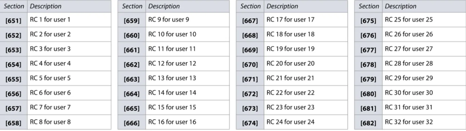
User Assignment for Remote Controls ... 36
Wireless Siren Programming ... 36
Wireless Siren Assignment ... 36
Wireless Siren Signal Strength ... 36
Wireless Siren Labels ... 36
Cancelling the Tamper Supervision for Wireless Sirens ... 37
Zone Options ...38
ATZ Options ... 38
General Zone Options ... 38
Miscellaneous System Options ... 39
System Timers ...39
Keypad Lockout ...39
Programming the Daylight Savings Feature ...39
Country Codes ... 40
Customized Daylight Savings Features ... 40
Partition Programming ...40
Partition Options ... 40
Partition Timers ... 41
Partition Labels ... 41
SMS and Bus Module Programming ...41
SMS Site Name ... 41
Bus Module Labels ... 41
Communication Programming ...42
Dialer Options ... 42
Event Call Direction Options ... 43
GSM Options ... 43
IP/GPRS Options ... 43
Report Codes and Partition Accounts ... 44
Landline and GSM Communication ... 44
Timers ... 44
VDMP3 Options ... 44
Test Report and Report Delays ... 45
GSM Settings ... 45
System and Communication Report Codes ...45
Entering Report Codes ... 45
Special Arming and Disarming Report Codes ... 45
Special Alarm Report Codes ... 45
System Trouble Report Codes ... 46
System Trouble Restore Codes ... 46
System Special Report Codes ... 46
Installer Function Keys ... 46
Contact ID Report Codes ... 47
Automatic Report Codes ... 49
Communication Report Codes ... 51
Communication Restore Report Codes ... 51
Software Options and Additional Timers ...51
Additional Communication Timers ... 51
WinLoad/BabyWare Options ... 52
IP and Software Configurations ...52
IP Account Numbers ... 52
Software and PCS Connection Settings ... 52
IP Receiver Configurations ... 52
Usability Sections ...53
Description of Sections [950], [955], and [960] ... 53
Description of Section [965] ... 53
Description of Sections [966] and [967] ... 54
Description of Sections [970], [975], and [980] ... 54
Label Programming with LCD Keypads ...54
Function keys ... 54
Catalogues of Special Characters ... 55
Keypad Letter Assignments ... 56
Trouble Display ...56
Product Compatibility Chart ...58
Hardware Connections ...59
Single Zone Inputs ... 59
Advanced Technology Zone (ATZ) Connections ... 59
Connecting Fire Circuits ... 60
Alarm Relay and PGM Connections ... 60
AC Power & Backup Battery Connections ... 60
Version 4.7/4.92/5.12 6 | Contents
MG5000 ... 61
MG5050 ... 62
SP4000 ... 63
SP5500 ... 64
SP6000 ... 65
SP65 ... 66
SP7000 ... 67
Appendix A ... 68
EN 50131 Programming ... 68
ATZ Options ... 68
General Zone Options ... 69
Miscellaneous System Options ... 69
System Timers ... 69
Keypad Lockout ... 70
Dialer Options ... 70
Timers ... 70
Special notes for MG5050 ... 70
List of Worksheets
Worksheet 1: Planning Bus Modules... 9Worksheet 2: Planning Wireless Keypads... 10
Worksheet 3: Planning Wireless Sirens... 10
Worksheet 4: Planning Programmable Outputs... 11
Worksheet 5: Planning Wireless Repeaters... 11
Worksheet 6: Planning Zones ... 11
Worksheet 7: Zone Definitions ... 17
Worksheet 8: Custom Zone Definitions ... 18
Worksheet 9: Zone Timers for the MG Series ... 18
Worksheet 10: Zone Timers for the SP Series... 18
Worksheet 11: Wireless Zones ... 19
Worksheet 12: Zone Report Codes ... 19
Worksheet 13: Zone Labels... 20
Worksheet 14: PGM Activation/Deactivation Events ... 27
Worksheet 15: PGM Delays ... 29
Worksheet 16: PGM Serial Numbers... 29
Worksheet 17: PGM Labels... 29
Worksheet 18: User System Codes... 30
Worksheet 19: User Code Options ... 30
Worksheet 20: User Report Codes... 31
Worksheet 21: User Labels ... 31
Worksheet 22: Wireless Repeater Assignment ... 31
Worksheet 23: Wireless Repeater Labels ... 33
Worksheet 24: Wireless Keypad Assignment ... 33
Worksheet 25: Wireless Keypad Labels ... 34
Worksheet 26: Programming Remote Controls ... 35
Worksheet 27: Wireless Siren Assignment ... 36
Worksheet 28: Wireless Siren Labels ... 36
Worksheet 29: System Timers... 39
Worksheet 30: Keypad Lockout... 39
Worksheet 31: Daylight Savings Time ... 40
Worksheet 32: Partition Timers ... 41
Worksheet 33: Partition Labels... 41
Worksheet 34: SMS Site Name... 41
Worksheet 35: Bus Module Labels ... 41
Worksheet 36: Report Codes and Partition Accounts ... 44
Worksheet 37: Landline and GSM Communication Settings ... 44
Worksheet 38: Communication Timers... 44
Worksheet 39: VDMP3 Maximum Attempts... 44
Worksheet 40: Test Report and Report Delays ... 45
Worksheet 41: GSM Settings (PCS series) ... 45
Worksheet 42: Special Arming and Disarming Report Codes... 45
Worksheet 43: Special Alarm Report Codes ... 45
Worksheet 44: Special Trouble Report Codes... 46
Worksheet 45: System Trouble Restore Codes ... 46
Worksheet 46: System Special Report Codes... 46
Worksheet 47: Communication Report Codes ... 51
Worksheet 48: Communication Restore Report Codes ... 51
Worksheet 49: Additional Communication Timers... 51
Worksheet 50: WinLoad/BabyWare Options ... 52
Worksheet 51: IP Account Numbers... 52
Worksheet 52: Software and PCS Connection Settings... 52
Worksheet 53: IP Receiver 1 Configuration... 53
Worksheet 54: IP Receiver 2 Configuration... 53
Worksheet 55: IP Receiver Backup Configuration ... 53
Worksheet 56: System Timers... 69
Worksheet 57: Keypad Lockout... 70
Version 4.7/4.92/5.12 Installer Quick Menu | 7
Zones
Delays
Time and Date
Walk Test Mode
Installer and Maintenance Codes
WinLoad/BabyWare
Monitoring Phone Number
Step Action Details
1 +installer code
= flash; programmed zones are lit (buttons or LED, depending on keypad); maintenance code may also be used
2 Zone number Two digits: 01 to 32
3 Enroll or erase zone
Wireless zone: open/close cover or press LEARN/TAMPER switch;
hardwired zone: press ENTER;
to erase a programmed zone, press and hold SLEEP for three seconds
4 Zone type See Zone Definitions on page 16, for the zone type
5 Assign partition (1 and/or 2 + ENTER)
If applicable, assign the zone to one or both partitions, and then press ENTER; by default, all zones are assigned to partition 1
NOTE: If applicable, partition 2 status LEDs display signal strength of selected wireless zone (4 LEDs = best signal; 1 LED = weak signal; no LEDs = hardwired panel/keypad zone).
Step Action Details
1 +installer code = flash; maintenance code may also be used
2
-3
1 = entry delay 1 Default: 045 sec. 2 = entry delay 2 Default: 045 sec. 3 = exit delay Default: 060 sec. 4 = bell cut-off Default: 004 min.
4 000 to 255 Entry/exit delay = seconds; bell cut-off = minutes
Step Action Details
1 +installer code = flash; maintenance code may also be used
2 + 5
-3 Time (HH:MM) If HH = 13 or more, go to step 5 4 Time format 1 = 24 hr. format, 2 = AM, 3 = PM 5 Date (YYYY/MM/DD) Enter the year/month/day
NOTE: For SP4000 and SP65 systems, the time format must be entered in 24 hr. format, therefore, omit step 4.
Step Action Details
1 +installer code = flash; maintenance code may also be used
2
-3 6 Activates or deactivates walk test mode
Step Action Details
1 +installer code = flash
2
-3
• 7 for installer code • 8 for
maintenance code
-4 Code Enter a four or six-digit code
5 Confirm code Re-enter the four or six-digit code, to confirm NOTE: To erase a code, press and hold SLEEP for three seconds.
Step Action Details
1 +installer code = flash
2
-3 9
-4 Phone # + ENTER Enter PC phone number (up to 32 digits), and then press ENTER
5 Panel ID Enter four-digit panel ID
6 PC password Enter four-digit PC password
NOTE: To erase the WinLoad/BabyWare phone number, panel ID, and PC password, press and hold SLEEPfor three seconds.
Step Action Details
1 +installer code = flash
2
-3 1
-4 Phone # + ENTER Enter monitoring station phone number (up to 32 digits), and then press ENTER
5 Partition 1 account # -6 • 1 for CID
• 2 for SIA SIA is not supported with GPRS/IP reporting 7 Partition 2 account #
-NOTE: To erase monitoring phone number, reporting format, and account numbers, press and hold SLEEP for three seconds.
Version 4.7/4.92/5.12 8 | Installer Quick Menu
Communicator
Cancel Communication
Keypad Programming
Assigning Keypad Zone Numbers
Entry Point Zone Assignment (StayD)
Keypad Input/Output Configuration (K636 V2.0 and higher)
PGMs
Step Action Details
1 +installer code = flash; maintenance code may also be used
2
-3
2 = backup phone #
-3 = personal phone #1 4 = personal phone #2 5 = personal phone #3 6 = personal phone #4 7 = personal phone #5 8 = pager #
4 Phone # + ENTER
Enter phone number (up to 32 digits), and then press ENTER to proceed to the next phone number, or go to step 5 if option 8 was selected
5 Message + ENTER Enter pager message, and then press ENTER; this step applies only to the pager number NOTE: To erase a phone number pager message, press and hold SLEEP for three seconds.
Step Action Details
1 +installer code = flash; maintenance code may also be used
2
-3 9 Cancels all communication with WinLoad,
BabyWare, and GSM module
Step Action Details
1 ENTER+installer code ARM + STAY= flash; maintenance code may also be used
2 Press and hold for
three seconds ARM + STAY = ON
3 Zone number + ENTER K35, K32, K32LCD, K32LX = two digits: 01 to 32; K636, K10V/H = one digit: 1 to 0 (10) NOTE: To erase a keypad zone number, press CLEAR, and then ENTER.
Step Action Details
1 ENTER+installer code ARM + STAY= flash 2 Press and hold OFFfor
three seconds ARM + STAY = ON
3 Zone number
K35, K32RF, K37, K32LCD, K32LX = two digits: 01 to 32; K636, K10V/H = one digit: 1 to 0 (10; maximum ten zones); the first zone
programmed will be the designated entry point and will flash; up to three more path zones can be added – these zones will light up and remain lit
4 ENTER Press ENTER to save and exit
Step Action Details
1 ENTER+installer code ARM + STAY= flash 2 Press and hold ENTER
for three seconds ARM + STAY = ON 3 Option 1
ON = output switches to ground following system arming (blue wire, maximum150 mA) OFF = input (keypad zone input)
4 Option 2 ON = output N.C.
OFF = output N.O.
NOTE: When configuring as an output, clear the assigned keypad zone first.
Step Action Details
1 +installer code = flash; maintenance code may also be used
2
-3 PGM number Two digits: 01 to 16
4 Enroll or erase PGM Wireless PGM = open/close cover; hardwired PGM = press ENTER
5 PGM type
1 = Follow button or 2 = Follow button or 3 = Follow zone 4 = Follow alarm 5 = Follow bell 6 = Follow arm 7 = Follow Stay arm 8 = Follow Sleep arm
6
If PGM type is 1, 2, 3, or 4, enter activation delay
1 = Follow 2 = 1 sec. 3 = 5 sec. 4 = 15 sec. 5 = 30 sec. 6 = 1 min. 7 = 5 min. 8 = 15 min. 9 = 30 min. If PGM type is 5,
proceed to the next available PGM
-If PGM type is 6, 7, or 8, enter 1 and/or 2 + ENTER
If system is partitioned, select partition(s), and then press ENTER to proceed to the next available PGM
7
If PGM type is 1 or 2, enter two-digit remote control #
01 to 32 (00 = all remote controls); the control panel proceeds to the next available PGM If PGM type is 3, enter
two-digit zone #
01 to 32 (00 = all zones); the control panel proceeds to the next available PGM If PGM type is 4, enter 1
and/or 2 + ENTER
If system is partitioned, select partition(s), and then press ENTER to proceed to the next available PGM
Version 4.7/4.92/5.12 System Planning | 9
System Planning
Bus Module Planning
NOTE: Paths are only applicable when StayD is enabled.
Worksheet 1: Planning Bus Modules
Serial # Sticker Description Path Zone (Entry Point) Path Zone Path Zone Path Zone
Bus Module 1
Bus Module 2
Bus Module 3
Bus Module 4
Bus Module 5
Bus Module 6
Bus Module 7
Bus Module 8
Bus Module 9
Bus Module 10
Bus Module 11
Bus Module 12
Bus Module 13
Bus Module 14
Version 4.7/4.92/5.12 10 | System Planning
Wireless Keypad Planning
NOTE: When deleting a wireless keypad (K32RF/K37) from the system, the corresponding StayD path zones will also be deleted.
Wireless Siren Planning
Worksheet 2: Planning Wireless Keypads
Serial # Sticker Description Path Zone (Entry Point) Path Zone Path Zone Path Zone
Wireless Keypad 1
Wireless Keypad 2
Wireless Keypad 3
Wireless Keypad 4
Wireless Keypad 5
Wireless Keypad 6
Wireless Keypad 7
Wireless Keypad 8
Worksheet 3: Planning Wireless Sirens
Serial # Sticker Description Serial # Sticker Description
Siren 1 Siren 3
Version 4.7/4.92/5.12 System Planning | 11
Programmable Output (PGM) Planning
Wireless Repeater Planning
Zone Planning
Worksheet 4: Planning Programmable Outputs
Serial # Sticker Description Serial # Sticker Description
PGM 1 PGM 9
PGM 2 PGM 10
PGM 3 PGM 11
PGM 4 PGM 12
PGM 5 PGM 13
PGM 6 PGM 14
PGM 7 PGM 15
PGM 8 PGM 16
Worksheet 5: Planning Wireless Repeaters
Serial # Sticker Description Serial # Sticker Description
Repeater 1 Repeater 2
Worksheet 6: Planning Zones
Arming Method Arming Method
Serial # Sticker Zone # Zone Description Stay Sleep Full Serial # Sticker Zone # Zone Description Stay Sleep Full
Zone
Zone
Version 4.7/4.92/5.12 12 | System Planning
Zone
Zone
Zone
Zone
Zone
Zone
Zone
Zone
Zone
Zone
Zone
Zone
Zone
Zone
Zone
Zone
Zone
Zone
Zone
Zone
Zone
Zone
Zone
Zone
Zone
Zone
Zone
Zone
Worksheet 6: Planning Zones (Continued)
Arming Method Arming Method
Version 4.7/4.92/5.12 Zone Recognition | 13
Zone Recognition
NOTE: For keypad zone programming, see Keypad Programming on page 8.
MG Series
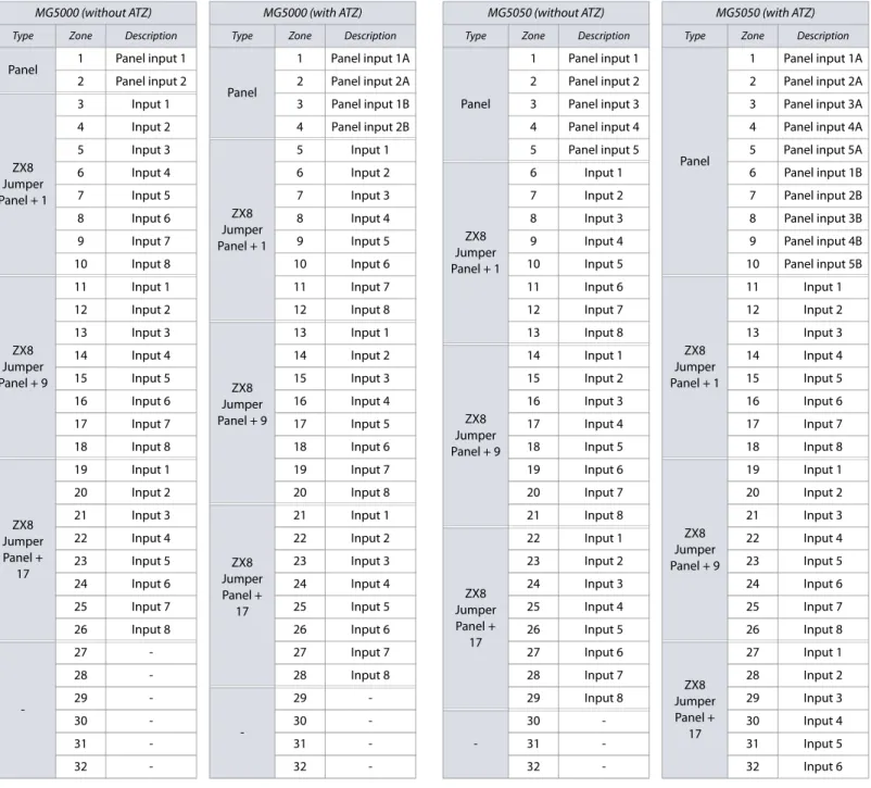
When expanding zones via ZX8, up to three ZX8 modules can be added to the system, and they are identified by the ZX8 three-position jumpers: +1, +9, and +17. Table 3 displays zone recognition information for MG control panels.
NOTE: If a device is assigned to a zone which is already programmed, a wireless zone will overwrite a keypad/hardwire zone and a keypad zone will overwrite a hardwire zone.
Table 3: Zone recognition information for the MG series
MG5000 (without ATZ) MG5000 (with ATZ) MG5050 (without ATZ) MG5050 (with ATZ)
Type Zone Description Type Zone Description Type Zone Description Type Zone Description
Panel 1 Panel input 1
Panel
1 Panel input 1A
Panel
1 Panel input 1
Panel
1 Panel input 1A
2 Panel input 2 2 Panel input 2A 2 Panel input 2 2 Panel input 2A
ZX8 Jumper Panel + 1
3 Input 1 3 Panel input 1B 3 Panel input 3 3 Panel input 3A
4 Input 2 4 Panel input 2B 4 Panel input 4 4 Panel input 4A
5 Input 3
ZX8 Jumper Panel + 1
5 Input 1 5 Panel input 5 5 Panel input 5A
6 Input 4 6 Input 2
ZX8 Jumper Panel + 1
6 Input 1 6 Panel input 1B
7 Input 5 7 Input 3 7 Input 2 7 Panel input 2B
8 Input 6 8 Input 4 8 Input 3 8 Panel input 3B
9 Input 7 9 Input 5 9 Input 4 9 Panel input 4B
10 Input 8 10 Input 6 10 Input 5 10 Panel input 5B
ZX8 Jumper Panel + 9
11 Input 1 11 Input 7 11 Input 6
ZX8 Jumper Panel + 1
11 Input 1
12 Input 2 12 Input 8 12 Input 7 12 Input 2
13 Input 3
ZX8 Jumper Panel + 9
13 Input 1 13 Input 8 13 Input 3
14 Input 4 14 Input 2
ZX8 Jumper Panel + 9
14 Input 1 14 Input 4
15 Input 5 15 Input 3 15 Input 2 15 Input 5
16 Input 6 16 Input 4 16 Input 3 16 Input 6
17 Input 7 17 Input 5 17 Input 4 17 Input 7
18 Input 8 18 Input 6 18 Input 5 18 Input 8
ZX8 Jumper Panel +
17
19 Input 1 19 Input 7 19 Input 6
ZX8 Jumper Panel + 9
19 Input 1
20 Input 2 20 Input 8 20 Input 7 20 Input 2
21 Input 3
ZX8 Jumper Panel +
17
21 Input 1 21 Input 8 21 Input 3
22 Input 4 22 Input 2
ZX8 Jumper Panel +
17
22 Input 1 22 Input 4
23 Input 5 23 Input 3 23 Input 2 23 Input 5
24 Input 6 24 Input 4 24 Input 3 24 Input 6
25 Input 7 25 Input 5 25 Input 4 25 Input 7
26 Input 8 26 Input 6 26 Input 5 26 Input 8
-27 - 27 Input 7 27 Input 6
ZX8 Jumper Panel +
17
27 Input 1
28 - 28 Input 8 28 Input 7 28 Input 2
29
-29 - 29 Input 8 29 Input 3
30 - 30
-30 - 30 Input 4
31 - 31 - 31 - 31 Input 5
| Zo ne R e co gn it io n V e rs io n 4. 7/ 4. 92 /5 .1 2
SP Series
When expanding zones via ZX8, up to three ZX8 modules can be added to the system, and they are identified by the ZX8 three-position jumpers: +1, +9, and +17. Table 4 displays zone recognition information for SP control panels.
Table 4: Zone recognition information for the SP series
SP4000 (without ATZ) SP4000 (with ATZ) SP5500 (without ATZ) SP5500 (with ATZ) SP6000 (without ATZ) SP6000 (with ATZ)
Type Zone Description Type Zone Description Type Zone Description Type Zone Description Type Zone Description Type Zone Description
Panel
1 Panel input 1
Panel
1 Panel input 1A
Panel
1 Panel input 1
Panel
1 Panel input 1A
Panel
1 Panel input 1
Panel
1 Panel input 1A
2 Panel input 2 2 Panel input 2A 2 Panel input 2 2 Panel input 2A 2 Panel input 2 2 Panel input 2A
3 Panel input 3 3 Panel input 3A 3 Panel input 3 3 Panel input 3A 3 Panel input 3 3 Panel input 3A
4 Panel input 4 4 Panel input 4A 4 Panel input 4 4 Panel input 4A 4 Panel input 4 4 Panel input 4A
ZX8 Jumper Panel +
1
5 Input 1 5 Panel input 1B 5 Panel input 5 5 Panel input 5A 5 Panel input 5 5 Panel input 5A
6 Input 2 6 Panel input 2B
ZX8 Jumper Panel +
1
6 Input 1 6 Panel input 1B 6 Panel input 6 6 Panel input 6A
7 Input 3 7 Panel input 3B 7 Input 2 7 Panel input 2B 7 Panel input 7 7 Panel input 7A
8 Input 4 8 Panel input 4B 8 Input 3 8 Panel input 3B 8 Panel input 8 8 Panel input 8A
9 Input 5
ZX8 Jumper Panel +
1
9 Input 1 9 Input 4 9 Panel input 4B
ZX8 Jumper Panel +
1
9 Input 1 9 Panel input 1B
10 Input 6 10 Input 2 10 Input 5 10 Panel input 5B 10 Input 2 10 Panel input 2B
11 Input 7 11 Input 3 11 Input 6
ZX8 Jumper Panel +
1
11 Input 1 11 Input 3 11 Panel input 3B
12 Input 8 12 Input 4 12 Input 7 12 Input 2 12 Input 4 12 Panel input 4B
ZX8 Jumper Panel +
9
13 Input 1 13 Input 5 13 Input 8 13 Input 3 13 Input 5 13 Panel input 5B
14 Input 2 14 Input 6
ZX8 Jumper Panel +
9
14 Input 1 14 Input 4 14 Input 6 14 Panel input 6B
15 Input 3 15 Input 7 15 Input 2 15 Input 5 15 Input 7 15 Panel input 7B
16 Input 4 16 Input 8 16 Input 3 16 Input 6 16 Input 8 16 Panel input 8B
17 Input 5
ZX8 Jumper Panel +
9
17 Input 1 17 Input 4 17 Input 7
ZX8 Jumper Panel +
9
17 Input 1
ZX8 Jumper Panel +
1
17 Input 1
18 Input 6 18 Input 2 18 Input 5 18 Input 8 18 Input 2 18 Input 2
19 Input 7 19 Input 3 19 Input 6
ZX8 Jumper Panel +
9
19 Input 1 19 Input 3 19 Input 3
20 Input 8 20 Input 4 20 Input 7 20 Input 2 20 Input 4 20 Input 4
ZX8 Jumper Panel +
17
21 Input 1 21 Input 5 21 Input 8 21 Input 3 21 Input 5 21 Input 5
22 Input 2 22 Input 6
ZX8 Jumper Panel +
17
22 Input 1 22 Input 4 22 Input 6 22 Input 6
23 Input 3 23 Input 7 23 Input 2 23 Input 5 23 Input 7 23 Input 7
24 Input 4 24 Input 8 24 Input 3 24 Input 6 24 Input 8 24 Input 8
25 Input 5
ZX8 Jumper Panel +
17
25 Input 1 25 Input 4 25 Input 7
ZX8 Jumper Panel +
17
25 Input 1
ZX8 Jumper Panel +
9
25 Input 1
26 Input 6 26 Input 2 26 Input 5 26 Input 8 26 Input 2 26 Input 2
27 Input 7 27 Input 3 27 Input 6
ZX8 Jumper Panel +
17
27 Input 1 27 Input 3 27 Input 3
28 Input 8 28 Input 4 28 Input 7 28 Input 2 28 Input 4 28 Input 4
-29 - 29 Input 5 29 Input 8 29 Input 3 29 Input 5 29 Input 5
30 - 30 Input 6
-30 - 30 Input 4 30 Input 6 30 Input 6
31 - 31 Input 7 31 - 31 Input 5 31 Input 7 31 Input 7
rs
ion 4.
7/
4.
92
/5.
1
2
Z
o
ne
Re
cog
n
iti
o
n |
1
5
NOTE: If a device is assigned to a zone which is already programmed, a wireless zone will overwrite a keypad/hardwire zone and a keypad zone will overwrite a hardwire zone.
SP65 (without ATZ) SP65 (with ATZ) SP7000 (without ATZ) SP7000 (with ATZ)
Type Zone Description Type Zone Description Type Zone Description Type Zone Description
Panel
1 Panel input 1
Panel
1 Panel input 1A
Panel
1 Panel input 1
Panel
1 Panel input 1A
2 Panel input 2 2 Panel input 2A 2 Panel input 2 2 Panel input 2A
3 Panel input 3 3 Panel input 3A 3 Panel input 3 3 Panel input 3A
4 Panel input 4 4 Panel input 4A 4 Panel input 4 4 Panel input 4A
5 Panel input 5 5 Panel input 5A 5 Panel input 5 5 Panel input 5A
6 Panel input 6 6 Panel input 6A 6 Panel input 6 6 Panel input 6A
7 Panel input 7 7 Panel input 7A 7 Panel input 7 7 Panel input 7A
8 Panel input 8 8 Panel input 8A 8 Panel input 8 8 Panel input 8A
9 Panel input 9 9 Panel input 9A 9 Panel input 9 9 Panel input 9A
ZX8 Jumper Panel +
1
10 Input 1 10 Panel input 1B 10 Panel input 10 10 Panel input 10A
11 Input 2 11 Panel input 2B 11 Panel input 11 11 Panel input 11A
12 Input 3 12 Panel input 3B 12 Panel input 12 12 Panel input 12A
13 Input 4 13 Panel input 4B 13 Panel input 13 13 Panel input 13A
14 Input 5 14 Panel input 5B 14 Panel input 14 14 Panel input 14A
15 Input 6 15 Panel input 6B 15 Panel input 15 15 Panel input 15A
16 Input 7 16 Panel input 7B 16 Panel input 16 16 Panel input 16A
17 Input 8 17 Panel input 8B
ZX8 Jumper Panel +
17 Input 1 17 Panel input 1B
ZX8 Jumper Panel +
9
18 Input 1 18 Panel input 9B 18 Input 2 18 Panel input 2B
19 Input 2
ZX8 Jumper Panel +
1
19 Input 1 19 Input 3 19 Panel input 3B
20 Input 3 20 Input 2 20 Input 4 20 Panel input 4B
21 Input 4 21 Input 3 21 Input 5 21 Panel input 5B
22 Input 5 22 Input 4 22 Input 6 22 Panel input 6B
23 Input 6 23 Input 5 23 Input 7 23 Panel input 7B
24 Input 7 24 Input 6 24 Input 8 24 Panel input 8B
25 Input 8 25 Input 7
ZX8 Jumper Panel +
9
25 Input 1 25 Panel input 9B
ZX8 Jumper Panel +
17
26 Input 1 26 Input 8 26 Input 2 26 Panel input 10B
27 Input 2
ZX8 Jumper Panel +
9
27 Input 1 27 Input 3 27 Panel input 11B
28 Input 3 28 Input 2 28 Input 4 28 Panel input 12B
29 Input 4 29 Input 3 29 Input 5 29 Panel input 13B
30 Input 5 30 Input 4 30 Input 6 30 Panel input 14B
31 Input 6 31 Input 5 31 Input 7 31 Panel input 15B
Version 4.7/4.92/5.12 16 | Zone Definitions
Zone Definitions
NOTE: If a device is assigned to a zone which is already programmed, a wireless zone will overwrite a keypad/hardwire zone and a keypad zone will overwrite a hardwire zone.
To define zones on your MG/SP control panel:
1. Press ENTER, and then enter your installer code (maintenance code may also be used). The ARM and STAY functions will flash. 2. Enter the three-digit zone number you wish to program (e.g., 001 to 032). The ARM and STAY functions will remain illuminated. 3. Enter a two-digit zone definition, by referring to table 5.
4. Assign a partition, by referring to table 6. By default, all zones are assigned to partition 1. 5. Select or deselect zone options, using buttons 1 to 8 (see tables 7 and 8).
6. Press ENTER to save and proceed to the next zone. 7. Repeat steps 3 to 6 for all remaining zones.
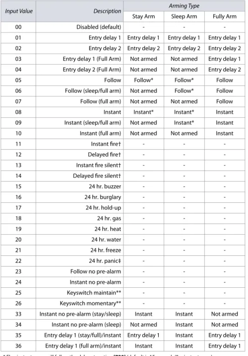
Table 5: Zone definitions for MG/SP panels
Input Value Description Arming Type
Stay Arm Sleep Arm Fully Arm
00 Disabled (default) - -
-01 Entry delay 1 Entry delay 1 Entry delay 1 Entry delay 1
02 Entry delay 2 Entry delay 2 Entry delay 2 Entry delay 2
03 Entry delay 1 (Full Arm) Not armed Not armed Entry delay 1
04 Entry delay 2 (Full Arm) Not armed Not armed Entry delay 2
05 Follow Follow* Follow* Follow
06 Follow (sleep/full arm) Not armed Follow* Follow
07 Follow (full arm) Not armed Not armed Follow
08 Instant Instant* Instant* Instant
09 Instant (sleep/full arm) Not armed Instant* Instant
10 Instant (full arm) Not armed Not armed Instant
11 Instant fire† - -
-12 Delayed fire† - -
-13 Instant fire silent† - -
-14 Delayed fire silent† - -
-15 24 hr. buzzer - -
-16 24 hr. burglary - -
-17 24 hr. hold-up - -
-18 24 hr. gas - -
-19 24 hr. heat - -
-20 24 hr. water - -
-21 24 hr. freeze - -
-22 24 hr. panic‡ - -
-23 Follow no pre-alarm - -
-24 Instant no pre-alarm - -
-25 Keyswitch maintain** - -
-26 Keyswitch momentary** - -
-33 Instant no pre-alarm (stay/sleep) Instant Instant Not armed
34 Instant no pre-alarm (sleep) Not armed Instant Not armed
35 Entry delay 1 (stay/full)/instant Entry delay 1 Instant Entry delay 1 36 Entry delay 1 (full arm)/instant Instant Instant Entry delay 1 * Flex-instant: zone will follow the delay at section [720] (default is 15 seconds/0 = instant zone).
** On-board, hardwire, control panel zones only.
† ZX8 inputs do not support fire zones. For two-wire smoke installations (not supported by SP4000/SP5500/ SP65), these definitions apply to zone 1 input only. Section [706], option 3, must be enabled. For four-wire smoke installations, use any panel, on-board zone input.
‡ This alarm will follow the panic 1 option (section [702], option 1).
Table 6: Partition assignment for MG/SP panels
Input Value Description
1 Assign to partition 1
2 Assign to partition 2
3 Assign to both partitions NOTE: When using the K636 keypad, only partition 1 is available.
Table 7: Zone options for MG/SP panels
Input
Value Description
1 Auto zone shutdown
2 Bypassable zone
3 RF zone supervision
6 Intellizone
7 Delay alarm transmission
8 Force zone
Input Value
Zone Alarm Type
4 5
OFF OFF Audible alarm
OFF ON Pulsed alarm
ON OFF Silent alarm
ON ON Report only
NOTE: For additional zone options, see Zone Options on page 38.
Table 8: Keyswitch options for MG/SP panels
Input
Value Description
1
-2
-3
-4 OFF = Disarm; ON = Disarm only if Stay/Sleep armed
5 Arm only
6 Stay arming*
7 Sleep arming*
8
-* Select only one. If all are OFF, keyswitch will regular arm.
rs
ion 4.
7/
4.
92
/5.
1
2
Zo
ne
Definitions
|
1
7
NOTE: See worksheet 11 on page 19, for assigning wireless zones to your MG/SP control panel.
Input
Value Description
Arming Type
Input
Value Description
Arming Type
Disarm Stay Arm
Sleep Arm
Fully
Arm Disarm
Stay Arm
Sleep Arm
Fully Arm
00 Zone disabled 16 24 hr. burglary
01 Entry delay 1 - 17 24 hr. hold-up
02 Entry delay 2 - 18 24 hr. gas
03 Entry delay 1 (Full Arm) - - - 19 24 hr. heat
04 Entry delay 2 (Full Arm) - - - 20 24 hr. water
05 Follow - 21 24 hr. freeze
06 Follow (sleep/full arm) - - 22 24 hr. panic
07 Follow (full arm) - - - 23 Follow no pre-alarm -
08 Instant - 24 Instant no pre-alarm -
09 Instant (sleep/full arm) - - 25 Keyswitch maintain
10 Instant (full arm) - - - 26 Keyswitch momentary
11 Instant fire 33 Instant no pre-alarm (stay/sleep) -
-12 Delayed fire 34 Instant no pre-alarm (sleep) - -
-13 Instant fire silent 35 Entry delay 1 (stay/full)/instant -
14 Delayed fire silent 36 Entry delay 1 (full arm)/instant -
15 24 hr. buzzer
Worksheet 7: Zone Definitions
Section Zone Description (see tables 3 and 4) Zone Definition Partition Zone Options Section Zone Description (see tables 3 and 4) Zone Definition Partition Zone Options
[001] 1 ________________________ ____/____ ______ 1 2 3 4 5 6 7 8 [017] 17 ________________________ ____/____ ______ 1 2 3 4 5 6 7 8
[002] 2 ________________________ ____/____ ______ 1 2 3 4 5 6 7 8 [018] 18 ________________________ ____/____ ______ 1 2 3 4 5 6 7 8
[003] 3 ________________________ ____/____ ______ 1 2 3 4 5 6 7 8 [019] 19 ________________________ ____/____ ______ 1 2 3 4 5 6 7 8
[004] 4 ________________________ ____/____ ______ 1 2 3 4 5 6 7 8 [020] 20 ________________________ ____/____ ______ 1 2 3 4 5 6 7 8
[005] 5 ________________________ ____/____ ______ 1 2 3 4 5 6 7 8 [021] 21 ________________________ ____/____ ______ 1 2 3 4 5 6 7 8
[006] 6 ________________________ ____/____ ______ 1 2 3 4 5 6 7 8 [022] 22 ________________________ ____/____ ______ 1 2 3 4 5 6 7 8
[007] 7 ________________________ ____/____ ______ 1 2 3 4 5 6 7 8 [023] 23 ________________________ ____/____ ______ 1 2 3 4 5 6 7 8
[008] 8 ________________________ ____/____ ______ 1 2 3 4 5 6 7 8 [024] 24 ________________________ ____/____ ______ 1 2 3 4 5 6 7 8
[009] 9 ________________________ ____/____ ______ 1 2 3 4 5 6 7 8 [025] 25 ________________________ ____/____ ______ 1 2 3 4 5 6 7 8
[010] 10 ________________________ ____/____ ______ 1 2 3 4 5 6 7 8 [026] 26 ________________________ ____/____ ______ 1 2 3 4 5 6 7 8
[011] 11 ________________________ ____/____ ______ 1 2 3 4 5 6 7 8 [027] 27 ________________________ ____/____ ______ 1 2 3 4 5 6 7 8
[012] 12 ________________________ ____/____ ______ 1 2 3 4 5 6 7 8 [028] 28 ________________________ ____/____ ______ 1 2 3 4 5 6 7 8
[013] 13 ________________________ ____/____ ______ 1 2 3 4 5 6 7 8 [029] 29 ________________________ ____/____ ______ 1 2 3 4 5 6 7 8
[014] 14 ________________________ ____/____ ______ 1 2 3 4 5 6 7 8 [030] 30 ________________________ ____/____ ______ 1 2 3 4 5 6 7 8
[015] 15 ________________________ ____/____ ______ 1 2 3 4 5 6 7 8 [031] 31 ________________________ ____/____ ______ 1 2 3 4 5 6 7 8
Version 4.7/4.92/5.12 18 | Zone Timers
Custom Zone Definitions
With MG/SP control panels you can create up to four custom zone definition templates (use worksheet 8). Custom zone definition templates (sections [033] to [036]) will overwrite zone definitions 33 to 36intable 5 on page 16. Modifications can be made in accordance with table 9 (Permitted zone definitions for MG/SP panels), on page 17.
Zone Timers
Use the following section to program zone timers for your MG/SP control panel. Use worksheets 9 and 10 to record your settings. NOTE: When both ATZ and EOL are enabled, the zone speed should not be set below 300 msec.
MG Series
SP Series
Worksheet 8: Custom Zone Definitions
Section Description Disarm Stay Arm Sleep Arm Full Arm
[033] Zone definition template 1 _____/_____ _____/_____ _____/_____ _____/_____ [034] Zone definition template 2 _____/_____ _____/_____ _____/_____ _____/_____ [035] Zone definition template 3 _____/_____ _____/_____ _____/_____ _____/_____ [036] Zone definition template 4 _____/_____ _____/_____ _____/_____ _____/_____
Worksheet 9: Zone Timers for the MG Series
Section Zone MG5000 MG5050 Data Description (default: 060)
[041] 1 (Z1) (Z1) ____/____/____ (000 to 255) x 10 msec. Speed of hardwire zone 1
[042] 2 (Z2) (Z2) ____/____/____ (000 to 255) x 10 msec. Speed of hardwire zone 2
[043] 3 (Z1 ATZ) (Z3) ____/____/____ (000 to 255) x 10 msec. Speed of hardwire zone 3 [044] 4 (Z2 ATZ) (Z4) ____/____/____ (000 to 255) x 10 msec. Speed of hardwire zone 4
[045] 5 (Z5) ____/____/____ (000 to 255) x 10 msec. Speed of hardwire zone 5
[046] 6 (Z1 ATZ) ____/____/____ (000 to 255) x 10 msec. Speed of hardwire zone 6
[047] 7 (Z2 ATZ) ____/____/____ (000 to 255) x 10 msec. Speed of hardwire zone 7
[048] 8 (Z3 ATZ) ____/____/____ (000 to 255) x 10 msec. Speed of hardwire zone 8
[049] 9 (Z4 ATZ) ____/____/____ (000 to 255) x 10 msec. Speed of hardwire zone 9
[050] 10 (Z5 ATZ) ____/____/____ (000 to 255) x 10 msec. Speed of hardwire zone 10
[051] 11 ____/____/____ (000 to 255) x 10 msec. Speed of hardwire zone 11
[052] 12 ____/____/____ (000 to 255) x 10 msec. Speed of hardwire zone 12
[053] 13 ____/____/____ (000 to 255) x 10 msec. Speed of hardwire zone 13
[054] 14 ____/____/____ (000 to 255) x 10 msec. Speed of hardwire zone 14
[055] 15 ____/____/____ (000 to 255) x 10 msec. Speed of hardwire zone 15
[056] 16 ____/____/____ (000 to 255) x 10 msec. Speed of hardwire zone 16
Worksheet 10: Zone Timers for the SP Series
Section Zone SP4000 SP5500 SP6000 SP65* SP7000** Data Description (default: 060)
[041] 1 (Z1) (Z1) (Z1) (Z1) (Z1) ____/____/____ (000 to 255) x 10 msec. Speed of hardwire zone 1
[042] 2 (Z2) (Z2) (Z2) (Z2) (Z2) ____/____/____ (000 to 255) x 10 msec. Speed of hardwire zone 2
[043] 3 (Z3) (Z3) (Z3) (Z3) (Z3) ____/____/____ (000 to 255) x 10 msec. Speed of hardwire zone 3
[044] 4 (Z4) (Z4) (Z4) (Z4) (Z4) ____/____/____ (000 to 255) x 10 msec. Speed of hardwire zone 4
[045] 5 (Z1 ATZ) (Z5) (Z5) (Z5) (Z5) ____/____/____ (000 to 255) x 10 msec. Speed of hardwire zone 5
[046] 6 (Z2 ATZ) (Z1 ATZ) (Z6) (Z6) (Z6) ____/____/____ (000 to 255) x 10 msec. Speed of hardwire zone 6 [047] 7 (Z3 ATZ) (Z2 ATZ) (Z7) (Z7) (Z7) ____/____/____ (000 to 255) x 10 msec. Speed of hardwire zone 7 [048] 8 (Z4 ATZ) (Z3 ATZ) (Z8) (Z8) (Z8) ____/____/____ (000 to 255) x 10 msec. Speed of hardwire zone 8
[049] 9 (Z4 ATZ) (Z1 ATZ) (Z9) (Z9) ____/____/____ (000 to 255) x 10 msec. Speed of hardwire zone 9
[050] 10 (Z5 ATZ) (Z2 ATZ) (Z1 ATZ) (Z10) ____/____/____ (000 to 255) x 10 msec. Speed of hardwire zone 10
[051] 11 (Z3 ATZ) (Z2 ATZ) (Z11) ____/____/____ (000 to 255) x 10 msec. Speed of hardwire zone 11
[052] 12 (Z4 ATZ) (Z3 ATZ) (Z12) ____/____/____ (000 to 255) x 10 msec. Speed of hardwire zone 12
[053] 13 (Z5 ATZ) (Z4 ATZ) (Z13) ____/____/____ (000 to 255) x 10 msec. Speed of hardwire zone 13
[054] 14 (Z6 ATZ) (Z5 ATZ) (Z14) ____/____/____ (000 to 255) x 10 msec. Speed of hardwire zone 14
[055] 15 (Z7 ATZ) (Z6 ATZ) (Z15) ____/____/____ (000 to 255) x 10 msec. Speed of hardwire zone 15
[056] 16 (Z8 ATZ) (Z7 ATZ) (Z16) ____/____/____ (000 to 255) x 10 msec. Speed of hardwire zone 16
* For zones 17-18 (ATZ), the zone timer is set to 600 msec. ** For zones 17-32 (ATZ), the zone timer is set to 600 msec.
Version 4.7/4.92/5.12 Wireless Zone Assignment | 19
Wireless Zone Assignment
Use the following section to program the wireless zones on your MG/SP control panel. Use worksheet 11 to record your settings.
NOTE: When assigning wireless zones, either enter the serial number or press TAMPER/LEARN. To delete the serial number, enter 000000.
Wireless Transmitter Signal Strength
The signal strength test for wireless transmitters is performed in sections [101] to [132]; these sections represent zones 1 to 32, respectively. To test the wireless transmitter strength of your various wireless devices, proceed as follows:
1. Enter the zone’s respective section (e.g., for zone 1, enter section [101]).
2. Press the transmitter’s anti-tamper switch and note the number of beeps which are emitted. As shown in table 10, the number of beeps correspond to a preset signal strength range.
NOTE: The visual representation of a transmitter’s signal strength is dependent on the type of keypad. For LED keypads, zones 1 through 10 will illuminate, depending on the signal strength. For instance, a signal strength of 8 will result in zones 1 through 8 to illuminate. For LCD keypads, a ten-level progress bar composed of arrows will appear, followed by the numeric value. For a signal strength of 8, eight arrows will appear, followed by the number 8.
Zone Report Codes and Labels
Use the following section to program zone report codes and labels on your MG/SP control panel.
Zone Report Codes
Use worksheet 12 to record your settings when programming zone report codes. Worksheet 11: Wireless Zones
Section Zone Wireless Zone (Serial #) Section Zone Wireless Zone (Serial #) Section Zone Wireless Zone (Serial #)
[061] 1 ___/___/___/___/___/___ [072] 12 ___/___/___/___/___/___ [083] 23 ___/___/___/___/___/___
[062] 2 ___/___/___/___/___/___ [073] 13 ___/___/___/___/___/___ [084] 24 ___/___/___/___/___/___
[063] 3 ___/___/___/___/___/___ [074] 14 ___/___/___/___/___/___ [085] 25 ___/___/___/___/___/___
[064] 4 ___/___/___/___/___/___ [075] 15 ___/___/___/___/___/___ [086] 26 ___/___/___/___/___/___
[065] 5 ___/___/___/___/___/___ [076] 16 ___/___/___/___/___/___ [087] 27 ___/___/___/___/___/___
[066] 6 ___/___/___/___/___/___ [077] 17 ___/___/___/___/___/___ [088] 28 ___/___/___/___/___/___
[067] 7 ___/___/___/___/___/___ [078] 18 ___/___/___/___/___/___ [089] 29 ___/___/___/___/___/___
[068] 8 ___/___/___/___/___/___ [079] 19 ___/___/___/___/___/___ [090] 30 ___/___/___/___/___/___
[069] 9 ___/___/___/___/___/___ [080] 20 ___/___/___/___/___/___ [091] 31 ___/___/___/___/___/___
[070] 10 ___/___/___/___/___/___ [081] 21 ___/___/___/___/___/___ [092] 32 ___/___/___/___/___/___
[071] 11 ___/___/___/___/___/___ [082] 22 ___/___/___/___/___/___
Table 10: Signal strength indicator for wireless transmitters
Number of Beeps Signal Strength Result
3 8 to 10 Strong signal
2 5 to 7 Average signal
1 1 to 4 Weak signal (relocate)
Worksheet 12: Zone Report Codes
Section Zone
Alarm Report Codes
Alarm Restore Report Codes
Tamper Report Codes
Tamper Restore Report Codes
Section Zone
Alarm Report Codes
Alarm Restore Report Codes
Tamper Report Codes
Tamper Restore Report Codes
[141] 1 ___/___ ___/___ ___/___ ___/___ [157] 17 ___/___ ___/___ ___/___ ___/___
[142] 2 ___/___ ___/___ ___/___ ___/___ [158] 18 ___/___ ___/___ ___/___ ___/___
[143] 3 ___/___ ___/___ ___/___ ___/___ [159] 19 ___/___ ___/___ ___/___ ___/___
[144] 4 ___/___ ___/___ ___/___ ___/___ [160] 20 ___/___ ___/___ ___/___ ___/___
[145] 5 ___/___ ___/___ ___/___ ___/___ [161] 21 ___/___ ___/___ ___/___ ___/___
[146] 6 ___/___ ___/___ ___/___ ___/___ [162] 22 ___/___ ___/___ ___/___ ___/___
[147] 7 ___/___ ___/___ ___/___ ___/___ [163] 23 ___/___ ___/___ ___/___ ___/___
[148] 8 ___/___ ___/___ ___/___ ___/___ [164] 24 ___/___ ___/___ ___/___ ___/___
[149] 9 ___/___ ___/___ ___/___ ___/___ [165] 25 ___/___ ___/___ ___/___ ___/___
[150] 10 ___/___ ___/___ ___/___ ___/___ [166] 26 ___/___ ___/___ ___/___ ___/___
[151] 11 ___/___ ___/___ ___/___ ___/___ [167] 27 ___/___ ___/___ ___/___ ___/___
[152] 12 ___/___ ___/___ ___/___ ___/___ [168] 28 ___/___ ___/___ ___/___ ___/___
[153] 13 ___/___ ___/___ ___/___ ___/___ [169] 29 ___/___ ___/___ ___/___ ___/___
[154] 14 ___/___ ___/___ ___/___ ___/___ [170] 30 ___/___ ___/___ ___/___ ___/___
[155] 15 ___/___ ___/___ ___/___ ___/___ [171] 31 ___/___ ___/___ ___/___ ___/___
Version 4.7/4.92/5.12 20 | Programmable Output Programming
Zone Labels
Use worksheet 13 to record your settings when programming zone labels.
Programmable Output Programming
Use the following section to program programmable outputs (PGMs) on your MG/SP control panel.
Programmable Output Recognition
NOTE: A wireless PGM module can be assigned to any PGM. These modules will work in parallel with the control panel output (not applicable to the SP4000).
Programmable Output on the K32LCD/K32LX
The on-board PGM of the K32LCD and K32LX (not programmable) will follow the arm status of any partition, via any arming method, including StayD. This only applies to versions 5.10 and higher, with an ECO number of J014.
Worksheet 13: Zone Labels
Section Zone Zone Label Section Zone Zone Label
[181] 1 __/__/__/__/__/__/__/__/__/__/__/__/__/__/__/__ [197] 17 __/__/__/__/__/__/__/__/__/__/__/__/__/__/__/__ [182] 2 __/__/__/__/__/__/__/__/__/__/__/__/__/__/__/__ [198] 18 __/__/__/__/__/__/__/__/__/__/__/__/__/__/__/__ [183] 3 __/__/__/__/__/__/__/__/__/__/__/__/__/__/__/__ [199] 19 __/__/__/__/__/__/__/__/__/__/__/__/__/__/__/__ [184] 4 __/__/__/__/__/__/__/__/__/__/__/__/__/__/__/__ [200] 20 __/__/__/__/__/__/__/__/__/__/__/__/__/__/__/__ [185] 5 __/__/__/__/__/__/__/__/__/__/__/__/__/__/__/__ [201] 21 __/__/__/__/__/__/__/__/__/__/__/__/__/__/__/__ [186] 6 __/__/__/__/__/__/__/__/__/__/__/__/__/__/__/__ [202] 22 __/__/__/__/__/__/__/__/__/__/__/__/__/__/__/__ [187] 7 __/__/__/__/__/__/__/__/__/__/__/__/__/__/__/__ [203] 23 __/__/__/__/__/__/__/__/__/__/__/__/__/__/__/__ [188] 8 __/__/__/__/__/__/__/__/__/__/__/__/__/__/__/__ [204] 24 __/__/__/__/__/__/__/__/__/__/__/__/__/__/__/__ [189] 9 __/__/__/__/__/__/__/__/__/__/__/__/__/__/__/__ [205] 25 __/__/__/__/__/__/__/__/__/__/__/__/__/__/__/__ [190] 10 __/__/__/__/__/__/__/__/__/__/__/__/__/__/__/__ [206] 26 __/__/__/__/__/__/__/__/__/__/__/__/__/__/__/__ [191] 11 __/__/__/__/__/__/__/__/__/__/__/__/__/__/__/__ [207] 27 __/__/__/__/__/__/__/__/__/__/__/__/__/__/__/__ [192] 12 __/__/__/__/__/__/__/__/__/__/__/__/__/__/__/__ [208] 28 __/__/__/__/__/__/__/__/__/__/__/__/__/__/__/__ [193] 13 __/__/__/__/__/__/__/__/__/__/__/__/__/__/__/__ [209] 29 __/__/__/__/__/__/__/__/__/__/__/__/__/__/__/__ [194] 14 __/__/__/__/__/__/__/__/__/__/__/__/__/__/__/__ [210] 30 __/__/__/__/__/__/__/__/__/__/__/__/__/__/__/__ [195] 15 __/__/__/__/__/__/__/__/__/__/__/__/__/__/__/__ [211] 31 __/__/__/__/__/__/__/__/__/__/__/__/__/__/__/__ [196] 16 __/__/__/__/__/__/__/__/__/__/__/__/__/__/__/__ [212] 32 __/__/__/__/__/__/__/__/__/__/__/__/__/__/__/__
Table 11: Programmable outputs for MG/SP panels
PGM PGM Output Control Panel
MG5000 MG5050 SP4000 SP5500 SP6000 SP65 SP7000
1 Control panel output 1
2 Control panel output 2 -
3 Control panel output 3 - - - Optional
4 Control panel output 4 - - - Optional -
5 Control panel relay - - - - Optional -
6 ZX8 ID = 1 output
7 ZX8 ID = 2 output
8 ZX8 ID = 3 output
-9 PGM4 relay 1
10 PGM4 relay 2
11 PGM4 relay 3
12 PGM4 relay 4
13 RTX3/RX1 output 1 - -
14 RTX3/RX1 output 2 - -
15 RTX3 output 3 (relay) - -
Version 4.7/4.92/5.12 Programmable Output Programming | 21
Description
of MG/SP Events
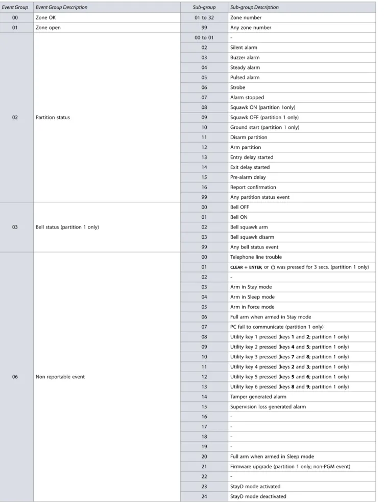
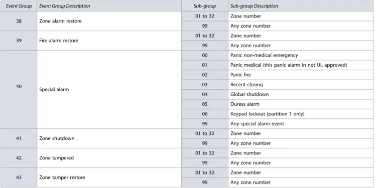
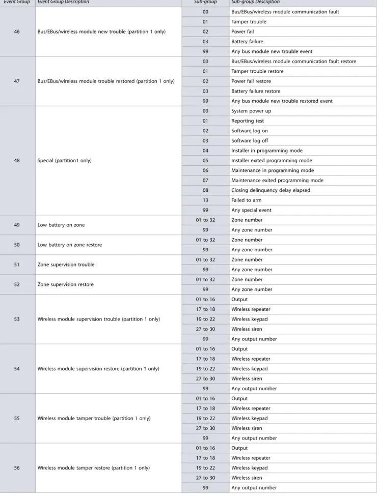
Table 12: List of events for MG/SP control panels
Event Group Event Group Description Sub-group Sub-group Description
00 Zone OK 01 to 32 Zone number
01 Zone open 99 Any zone number
02 Partition status
00 to 01 -02 Silent alarm 03 Buzzer alarm 04 Steady alarm 05 Pulsed alarm
06 Strobe
07 Alarm stopped
08 Squawk ON (partition 1only) 09 Squawk OFF (partition 1 only) 10 Ground start (partition 1 only) 11 Disarm partition
12 Arm partition 13 Entry delay started 14 Exit delay started 15 Pre-alarm delay 16 Report confirmation 99 Any partition status event
03 Bell status (partition 1 only)
00 Bell OFF
01 Bell ON
02 Bell squawk arm 03 Bell squawk disarm 99 Any bell status event
06 Non-reportable event
00 Telephone line trouble
01 CLEAR + ENTER, or was pressed for 3 secs. (partition 1 only)
02
-03 Arm in Stay mode 04 Arm in Sleep mode 05 Arm in Force mode
06 Full arm when armed in Stay mode 07 PC fail to communicate (partition 1 only) 08 Utility key 1 pressed (keys 1 and 2; partition 1 only) 09 Utility key 2 pressed (keys 4 and 5; partition 1 only) 10 Utility key 3 pressed (keys 7 and 8; partition 1 only) 11 Utility key 4 pressed (keys 2 and 3; partition 1 only) 12 Utility key 5 pressed (keys 5 and 6; partition 1 only) 13 Utility key 6 pressed (keys 8 and 9; partition 1 only) 14 Tamper generated alarm
15 Supervision loss generated alarm
16
-17
-18
-19
-20 Full arm when armed in Sleep mode
21 Firmware upgrade (partition 1 only; non-PGM event)
22
-23 StayD mode activated 24 StayD mode deactivated
Version 4.7/4.92/5.12 22 | Programmable Output Programming
06 (Cont.)
Non-reportable event (Cont.)
25 IP registration status change 26 GPRS registration status change 27 Armed with trouble(s) 28 Supervision alert 29 Supervision alert restore
30 Armed with remote with low battery 99 Any non-reportable event 08 Button pressed on remote (see Default Data B, in worksheet 26
on page 35)
01 to 32 Remote control number 99 Any remote control number 09 Button pressed on remote (see Default Data C, in worksheet 26
on page 35)
01 to 32 Remote control number 99 Any remote control number 10 Button pressed on remote (see Default Data D, in worksheet 26
on page 35)
01 to 32 Remote control number 99 Any remote control number 11 Button pressed on remote (see Default Data E, in worksheet 26
on page 35)
01 to 32 Remote control number 99 Any remote control number
12 Cold start wireless zone 01 to 32 Zone number
99 Any zone number
13 Cold start wireless module (partition 1 only)
01 to 16 Output number 17 to 18 Wireless repeater 19 to 26 Wireless keypad 27 to 30 Wireless siren
99 Any output number
14 Bypass programming 01 to 32 User number
99 Any user number 15 User code activated output (partition 1 only) 01 to 32 User number
99 Any user number
16 Wireless smoke maintenance signal 01 to 32 Zone number
99 Any zone number
17 Delay zone alarm transmission 01 to 32 Zone number
99 Any zone number 18 Zone signal strength weak 1 (partition 1 only) 01 to 32 Zone number
99 Any zone number 19 Zone signal strength weak 2 (partition 1 only) 01 to 32 Zone number
99 Any zone number 20 Zone signal strength weak 3 (partition 1 only) 01 to 32 Zone number
99 Any zone number 21 Zone signal strength weak 4 (partition 1 only) 01 to 32 Zone number
99 Any zone number 22 Button pressed on remote (see option 5, in table 22 on page 34) 01 to 32 Remote control number
99 Any remote control number 23 Button pressed on remote (see option 6, in table 22 on page 34) 01 to 32 Remote control number
99 Any remote control number
24 Fire delay started 01 to 32 Zone number
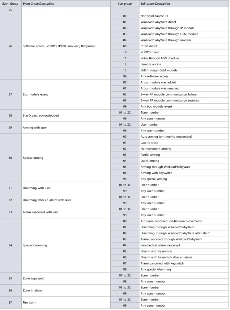
99 Any zone number Table 12: List of events for MG/SP control panels (Continued)
![Table 25: Description of sections [700] to [704]](https://thumb-us.123doks.com/thumbv2/123dok_us/8463758.2255446/37.1188.69.1135.138.798/table-description-sections.webp)
