for HP OpenView/UNIX
Version 2.1.0
Operation
TEAM 540
GDC 058R694-V210
Issue 1 - July 1997
General DataComm
Warranty
General DataComm warrants that its equipment is free from defects in materials and workmanship. The warranty period is one year from the date of shipment. GDC's sole obligation under its warranty is limited to the repair or replacement of the defective equipment provided it is returned to GDC, transportation prepaid, within a reasonable period. This warranty will not extend to equipment subjected to accident, misuse, or alterations or repair not made by GDC or authorized by GDC in writing. The foregoing warranty is exclusive and in lieu of all other warranties, express or implied, including but not limited to, warranties of merchantability and fitness for purpose.
Trademarks and Patents
General DataComm, the General DataComm logo and the following are trademarks of General DataComm, Inc in the United States and other countries: ACCULINE, ANALOOP, AUTOFRAME, BERT 901, DATACOMM SECURE-PAK, DATALOOP, DIGIDIAL, ENmacs, FASTPRO, FIRST RESPONSE, GDC, GDC APEX, GENERAL DATACOMM X-PRESS, GEN*NET, GEN*PAC, IMAGE*TMS, KILOMUX, LAN*TMS, MEGA*BRIDGE, MEGAMUX, MEGAMUX TMS, MEGANET, MEGASPLIT, MEGASWITCH, MEGAVIEW, NETCON, NETSWITCH, NMC, QUIKSHIPPERS, SERVI-CHECK, SERVI-SNAP, WINmacs.
ANALOOP and DATALOOP respectively are protected by U.S. patents 3,655,915 and 3,769,454. All other products or services mentioned in this document are identified by the trademarks, service marks, or product names as designated by the companies who market those products. Inquiries concerning such trademarks should be made directly to those companies.
Copyright
© 1997 General DataComm, Inc. All rights reserved. P.O. Box 1299, Middlebury, Connecticut 06762-1299 U.S.A.
This publication and the software it describes contain proprietary and confidential information. No part of this document may be copied, photocopied, reproduced, translated or reduced to any electronic or machine-readable format without prior written permission of General DataComm, Inc.
The information in this document is subject to change without notice. General DataComm assumes no responsibility for any damages arising from the use of this document, including but not limited to, lost revenue, lost data, claims by third parties, or other damages. If you have comments or suggestions concerning this manual, please write to Technical Publication Services or call 1-203-758-1811.
Preface
Introduction
Overview ... 1-1 TEAM 540 Network Manager Features ... 1-1 SNMP 540 and SNMP 540EN DSU Features ... 1-2 OpenView Information ... 1-3
Installation
Overview ... 2-1
Agent Configuration
Introduction ... 3-1 To Start Agent Configuration... 3-1 Agent Configuration Window ... 3-1 Menu Selection Definitions ... 3-2 System Options... 3-3 Community Names Options ... 3-4 Community Name MIB Description... 3-5 Adding a Community Name ... 3-5 Editing a Community Name ... 3-6 Deleting a Community Name ... 3-6 Trap Options... 3-6 Traps Supported ... 3-7 Fields... 3-7 Adding a Trap Definition... 3-8 Editing a Trap Definition ... 3-8 Deleting a Trap Definition ... 3-8 IP Routing Options ... 3-8 Fields... 3-9 SNMP IP Routing ... 3-10
ii Table of Contents
Operations
Introduction ... 4-1 TEAM 540 Access... 4-1 Map Window Menu Bar Access ... 4-1 SNMP 540 Front Panels... 4-2 Performance Functions ... 4-5 Alarms... 4-5 Line Statistics ... 4-7 DTE Status ... 4-7 Configuration Functions ... 4-9 Configuration ... 4-9 Maintenance ... 4-9 Diagnostics ... 4-9 Miscellaneous Functions ... 4-10 Information... 4-10 Line Statistics ... 4-10
Configuration
Introduction ... 5-1 To Start TEAM 540 Configuration ... 5-1 Templates... 5-1 Configuration Procedure... 5-1 Configuration Option Values ... 5-2 Main Configuration Window... 5-2 Main Configuration Window Fields... 5-3 Configuration ... 5-4 DDS Options... 5-4 Buttons ... 5-5 Options ... 5-5 DTE Options... 5-7 Buttons ... 5-8 Options ... 5-8 Alarms Reported... 5-10 Buttons ... 5-11 Options ... 5-11Maintenance
Introduction ... 6-1 To Start TEAM 553S Maintenance ... 6-1 Maintenance Window Buttons ... 6-1Table of Contents iii
Diagnostics
Introduction ... 7-1 Diagnostics Window ... 7-1 Tests... 7-1 Diagnostic Test Procedure ... 7-2 Line Loop ... 7-3 Remote Loop ... 7-3 Diagnostic History... 7-4
Scope
This manual describes how to operate the TEAM 540 Network Manager, Version 2.1.0. It assumes familiarity with HP OpenView.
The TEAM 540 software is an HP OpenView application that employs the Simple Network Management Protocol (SNMP) to configure and control the operation of GDC SNMP 540 IFP and SNMP 540EN Data Service Units (DSUs). The DSUs connect data terminal equipment (DTE) to Dataphone Digital Service (DDS) supported by a Telco or other service supplier. This manual assumes a working knowledge of DDS, and DSU functions and operation.
Revision History
This is Issue 1 of the manual for TEAM 540 Version 2.1.0. This version of the application has been upgraded to be compatible with Version 4.1 of the HP OpenView Operating System.
Organization
This manual has seven chapters. The information is arranged as follows: • Chapter 1 - Introduction describes the product and its features.
• Chapter 2 - Installation describes preliminary steps for setup and use of the product. • Chapter 3 - Agent Configuration describes the configuration required to support SNMP
communications between the workstation that runs the application and the SNMP 540 IFP and SNMP 540EN DSUs.
• Chapter 4 - Operation provides directions for accessing the smaller individual
applications that are responsible for the TEAM 540 functions. It describes how to access the functions from a shelf map window menu bar, and from the Select menu of a DSU front panel display. The chapter provides full descriptions of the TEAM 540 applications that display read-only windows. It provides access information for the applications that display read/write windows and require greater operator interaction.
• Chapter 5 - Unit Configuration provides instructions for accessing the Configuration application and using it to set operating parameters in a selected DSU. The chapter covers how to save configuration changes to the unit or as templates at the controller
workstation, and defines the parameters you can set.
• Chapter 6 - Maintenance provides instructions for accessing the Maintenance application and using it to control functions of the DSU.
• Chapter 7 - Diagnostics provides instructions for accessing the Diagnostics application window and using it to perform test procedures.
vi Preface
Document Conventions
Level 1
paragraph headers introduce major topics.Level 2
paragraph headers introduce subsections of major topics.Level 3 paragraph headers introduce subsections of secondary topics. .
Related Publications
The following documents have additional information that may be helpful when using this product:
• SNMP 540 IFP Data Service Unit
Operation and Installation Manual, Issue 2 058R134-000 • SNMP 540EN Data Service Unit
Installation and Operation Manual 058R136-000
GDC publication numbers are used to track and order technical manuals. Publication numbers use the following format:
GDC NNNRnnn-000 or GDC NNNRnnn-Vnnn
NNN identifies the product family R denotes a technical publication
nnn a number assigned by Technical Publications 000 identifies a hardware product and does not change
Vnnn the software version associated with a product may be updated periodically The Issue Number on the title page only changes when a hardware manual is revised or when a manual is reprinted for some other reason; it does not automatically change when the software is updated. A new Software Version is always Issue 1. Other specialized publications such as Release Notes or Addenda may be available depending on the product.
Service and Support
General DataComm is committed to providing the service and support needed to install, man-age, and maintain your equipment. For information about service programs or for assistance with your support requirements, contact your local Sales Representative or call General Data-Comm Service at the 24-hour toll free number listed below.
• in the U.S. dial 1-800-243-1030 • outside the U.S. dial 1-203-598-7526
Be ready with the site name and phone number and a description of the problem and the next available support representative will promptly return your call.
Notes present special instructions, helpful hints or general rules. NOTE
Preface vii
Hands-on training courses are provided by GDC Educational Services. Courses range from basic data communications, modems and multiplexers, to complex network and ATM systems and are taught in Connecticut or at a customer location. Call 1-800-243-1030 and follow the menu instructions to discuss educational services or to receive a course schedule.
Overview
The General DataComm TEAM 540 Network Manager enables you to monitor and control GDC SNMP 540 devices from a central location. The SNMP 540 communication products are the SNMP 540/IFP Data Service Unit (DSU) and the SNMP 540EN DSU.
The manager, based on the HP OpenView platform, provides access to product functions by means of the Simple Network Management Protocol (SNMP). You can start at the top level with an IP map of the network and descend through a hierarchy of submaps that extends to the segment and node level.
Icons appear on the manager screen colored to indicate alarm status using standard HP Open-View color coding, thereby presenting an immediate top level view of trouble spots. At the de-vice level you can display an accurate view of an SNMP 540 front panel, including colored LEDs. An operator can monitor the status of a DSU remotely from a workstation located any-where in the network without having the actual unit at hand or having personnel at remote sites. If problems occur during its operations, the manager indicates them by displaying a message, or by causing the fields involved to blink.
TEAM 540 Network Manager Features
The Team 540 Network Manager features the following capabilities: • Graphical representation of devices within HP OpenView • Monitoring SNMP 540 and SNMP 540EN DSUs
• Configuring SNMP 540 and SNMP 540EN DSUs
• Diagnostic function control for SNMP 540 and SNMP 540EN DSUs The following are Team 540 Network Manager applications:
Unit Configuration - enables you to configure the operating characteristics of SNMP 540
DSUs, and to select alarms to report or mask (not report).
Agent Configuration - enables you to configure aspects of how the SNMP 540 and SNMP
540EN DSUs function as SNMP agents: System Options, Community Names, Traps, and IP Routing.
Alarms - displays the alarm status of SNMP 540 and SNMP 540EN DSUs.
EIA Status - indicates the status of SNMP 540 and SNMP 540EN DSU EIA connections. Front Panel - displays graphic representations of the SNMP 540 and SNMP 540EN DSU front
panels, reflecting the current state of their LED indicators.
Line Statistics - displays a variety of line parameters associated with the SNMP 540 and SNMP
540EN DSUs.
Diagnostics - enables you to run Line Loopback and Remote Loopback diagnostic tests on
SNMP 540 and SNMP 540EN DSUs.
1-2 Introduction
Download - enables you to download operating software revisions to SNMP 540 and SNMP
540EN DSUs using the Trivial File Transfer Protocol (TFTP).
The manager is OSF/Motif compliant and is integrated into HP OpenView on the Sun and HP platforms. The manager is integrated with HP OpenView Windows (OVW) in the following areas:
• Provides Telnet Access for the SNMP 540 and SNMP 540EN DSUs. (The DSU manuals each cover Telnet access under the heading Terminal Interface (TELNET) in their Operation chapters.)
• Integrated with HP IP Discovery to display the correct symbols for the SNMP 540 and SNMP 540EN DSUs
• Integrated with the OVW Menu Bar using Application and Field Registration Files • Integrated with the OVW Help System.
SNMP 540 and SNMP 540EN DSU Features
An SNMP 540 or SNMP 540EN DSU provides the following features:
• Combined CSU/DSU functionality to provide direct connect capability for DATAPHONE Digital Service (DDS)
• Operation in Standard DDS, DDS with Secondary Channel, and 64k Clear Channel environments
• Full compatibility with Simple Network Management Protocol (SNMP), which provides complete software control for centralized configuration and diagnostic testing
capabilities
• Operates in conjunction with an SNMP controller to provide comprehensive, non-interfering network management.
• Supports local SNMP functions, using configurable IP address and subnet mask, through one of three model-dependent communication modes:
• Point to Point Protocol (PPP) or Serial Line Interface Protocol (SLIP) • Ethernet LAN
• Inband Communication (SNMP 540 IFP DSU only)
• Supports remote SNMP functions by means of a GDC V.F 28.8 modem, using configurable IP address and subnet mask, through PPP or SLIP
• Intelligent Front Panel (IFP) permits convenient local access to configuration and diagnostic functions, and serves as the means of configuring IP addresses and subnet masks for SNMP control
• Provides limited management capabilities through a terminal interface accessible by either a VT100-compatible terminal or a computer running the Telnet protocol. Telnet uses the same local or remote IP address access that supports SNMP
• Supports one high-speed serial data port for customer equipment:
standard interface is selectable to be ITU-T V.35- or EIA-232-compatible EIA-530-compatible channel interface card is available as an option
Introduction 1-3
• Permits configuration of network transmitter timing from a variety of sources: Slave timing, recovered from received network data
Channel (DTE) timing Internal clock
OpenView Information
For information regarding OpenView, refer to your OpenView documentation.
TEAM 540 supports the OpenView capability of selecting multiple icons in a map window in order to launch the same application window for multiple units simultaneously. You can select multiple icons either by clicking and dragging to “box” the icons you intend to select, or by clicking on icons individually while holding down the Control and Shift keys.
2 Installation
Overview
Use the following instructions to integrate your devices with the network. 1. Get IP Address(es) and network mask(s) from your system administrator.
2. Set the IP parameters and network element configuration for both units through the SNMP 540 terminal interface. You have the option of changing the Super Community Name (Password). If you change it, note the name that you enter – you need it for later steps.
3. Connect devices to Telco, then perform a Remote Loopback with Self Test on the SNMP 540 units to verify the line installation. The test can be commanded by means of the ter-minal interface on any SNMP 540 DSU; it can be commanded by means of the Intelligent Front Panel on an SNMP 540 IFP DSU.
4. Connect both SNMP 540 units to their routers.
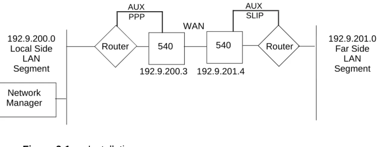
For a SNMP 540 circuit that uses the router Auxiliary Port (or Terminal Server, etc.) as a PPP or SLIP Port, configure the Remote SNMP 540 unit with the same network field as that of the far side LAN segment. Configure the Master SNMP 540 unit with the same network field as the local side LAN segment. For an example, see Figure 2-1, which il-lustrates a Class C network.
Figure 2-1 Installation
5. Confirm that the routers are up (connected and passing data). To confirm that the WAN connection is up, Ping a device on the remote segment.
6. If HP OpenView is not installed, install it and the GDC S/W application.
7. We recommend that you create a seed file for HP OpenView. HP OpenView reads this file when it starts the Discovery process and discovers the IPs first. For information con-cerning creation of a seed file, refer to your HP OpenView documentation.
540 540 Router Network
Manager
Router 192.9.201.0Far Side LAN Segment 192.9.201.4 192.9.200.3 192.9.200.0 Local Side LAN Segment WAN AUX PPP AUX SLIP
2-2 Installation
8. In the Root map window menu bar, pull down the Options menu and select SNMP Con-figuration, then add a node for the SNMP 540 unit. Enter the:
• Target (IP Address) • Community (Name) • Set Community (Name)
• Time-out (20 seconds recommended) • Retry Count (3 retries recommended)
Use the Community Name that you used in Step 2. If you did not change the Super Com-munity Name in Step 2, use GDCGDC.
9. Locate the SNMP 540 Icon(s) on the map. (One possibility is to select Locate>Ob-jects>By Attribute. You can use any map for this. This selection opens a pop-up. Use it to locate the Icon.)
10. Select an Icon, then select Configuration>Agent Configuration from the Root window menu bar.
11. In the window that opens, enter the Name, Location, Contact, etc., then save your input. 12. To add a Community Name(s), select Community Name Access from the File menu. 13. Enter the Super Community Name as in Step 2.
14. Enter or modify Community Name accounts. Ensure that at least one account has read/ write permissions then save your configuration.
15. To set up the alarm reporting Traps, select View>Traps from the View menu on the Con-figuration window.
16. Enter the IP Address of the Manager, then enter 162 for the port. 17. Enter a Community Name.
18. Change Status to Valid and click on Add.
19. In the menu bar, pull down the File menu and Save your input. 20. Exit from all GDC application windows that are open.
21. In the Root map window menu bar, pull down the Options menu and select SNMP Con-figuration.
22. Change Community (Name) and Set Community (Name) fields to the one entered in Step 14 that has read/write permission.
Introduction
The Agent Configuration function of the TEAM 540 software governs the operation of SNMP communications. It is principally concerned with Internetwork Protocol (IP) addressing and routing for the SNMP 540 DSU. You must insure that these characteristics are properly set in order for the unit to communicate with the TEAM application workstation.
To Start Agent Configuration
You can start the TEAM 540 Agent Configuration application either from a map window menu bar or from a Front Panel display Select button menu. In both menu systems Agent Configuration is a selection from the Configuration menu.
On the TEAM Universe submap in OpenView, first select the SNMP 540 DSU on which you intend to perform Agent Configuration by clicking the mouse on its icon symbol. Then select the Agent Configuration option from the Configuration menu.
From a Front Panel display click first on the Select button, then on Configuration, and then on Agent Configuration.
Agent Configuration Window
You can display the Agent Configuration functions individually: System Options, Community Name Options, Trap Options, and IP Routing Options. This is the initial condition when you launch the Agent Configuration application. System Options is the first to appear.
You can select All Agent Options in the Agent Configuration window View menu, described below, to display the Agent Configuration window with all four categories of options. The Agent Configuration functions cannot all fit on-screen at once when displayed in a single window, so the application provides a scroll bar on the right hand side for moving through them.
The Agent Configuration window has three pull down menus: File, Edit, and View. The contents of the menus appear below.
3-2 Agent Configuration
Menu Selection Definitions
File menu:
Save to Unit1 – sends the displayed configuration to the unit. If the configuration has changed, a pop-up suggests that this new configuration be saved. A footer message indicates that
configuration categories are being downloaded.
Load Template... – opens a window listing all Agent Configuration templates stored on the
workstation, from which you may select a template file to display
Save Template – stores the displayed configuration, with any changes you have made, under the
currently selected template file name
1.Unit Configuration application only (not applicable to Template application)
Menus Menu Selections File
Refresh Save to Unit Load Template... Save Template (*)
Save As New Template (*) Delete Template...
Compare to Template... Community Name Access... Exit Edit Discard Edits View System Community Name Traps IP Routing All Agent Options
* Displays Needed when there are pending changes, Unneeded when there are no pending changes
Agent Configuration 3-3
Save as New Template – prompts you for a new template file name and stores the displayed
configuration as a template under the name you supply
Delete Template... – removes the selected template from the disk
Compare to Template... – compares the displayed configuration to a selected template file
Community Name Access...1 – lets you access the Community Name Table via the Administrative Community Name assigned in the unit. (The default for this Administrative Community Name is GDCGDC.) Note that without this Administrative Community Name the Community Name Table appears shaded and contains no information.
Exit – dismisses the window.
Edit menu:
Discard Edits – cancels changes and restores the displayed configuration field values to their
stored values View menu:
System –displays the System Options portion of the Agent Configuration window Community Name – displays the Community Names Options portion of the Agent
Configuration window
Traps – displays the Trap Options and Trap Address Options portion of the Agent Configuration
window
IP Routing – displays the IP Routing Options portion of the Agent Configuration window All Agent Options – displays all portions of the Agent Configuration option window with scroll
bar for moving through them
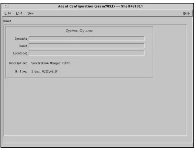
System Options
The Agent Configuration System Options window (Figure 3-1) contains three text input fields and two display fields. The information you store in this window is simply text to identify the unit, and to provide an operator at a TEAM management workstation with the name of a person on-site where the equipment is located to contact if need arises.
3-4 Agent Configuration
System Options Fields
The three text input fields in the System Options window are labeled Contact, Name, and Location. The application does not enforce any restrictions on the text you can insert in these fields, but the recommendation is that you record the following information:
Contact – name and telephone number of the on-site person responsible for care and
maintenance of the unit
Name – identifier assigned to the unit
Location – address of the site where the unit is located
To enter or edit text in any of the input fields, click in the field, highlight existing text if you need to change or replace it, and type.
The window also includes the display fields:
Description – displays the factory configured description of the selected DSU
Up Time – displays time elapsed since the last time a reset was performed or power was
cycled at the unit
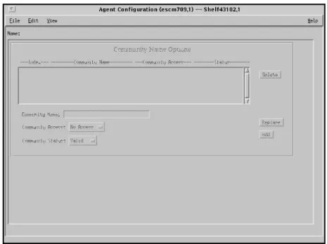
Community Name Options
The Agent Configuration Community Name Options window enables you to define the SNMP Community Names that have access to the unit.
This includes assigning each an access level. A unit can access the MIBs provided that the unit supplies the appropriate Community Name. Each Community Name, which is in fact a password, has an access level associated with it, one that you assign. If another unit supplies the proper Community Name, that unit is granted the access associated with the name. For example, if a Community Name of Public has an access level of Read Only, then a unit supplying this name can only read the MIBs.
Agent Configuration 3-5
SNMP uses Community Names to restrict access to an agent. There are three access levels to MIB variables:
Read/Write Read No Access
You can add, delete, and view Community Names in a unit. A unit can store up to five
Community Names, each with its associated access and current status. Access in the unit can be defined as read-only, read-write, or noaccess. A special Community Name is required to add and delete entries in the table. It acts as a superuser Community Name and can be used to read or write any MIB Object. Factory default for this Community Name is GDCGDC. When the unit is initially installed and powered up, it contains one default Community Name, public, having read-only access. You can change the default Community Name.
At least one Community Name with read-write access must be set in the Community Name Table before other MIB objects can be set. Use the special Community Name to set the first privileged Community Name, then use that privileged Community Name to set all other MIB objects.
Community Name MIB Description
In the GDCCMN-MIB there is a Community Name group. The maximum number of Community Names at any one time can be determined by reading the MIB variable cmnCommunityNumber. The Community Name Table is in non-volatile RAM and need not be recreated each time the unit is powered up.
The following information is defined in the Community Name Table:
CommunityName – string of up to 31 characters holds the Community Name; if you enter more than 31 characters, the unit ignores those in excess of 31
CommunityAccess – access associated with the Community Name (read-write, read-only, noaccess)
CommunityStatus – status of the row entry, which is always Valid; when you set this status to Invalid the application deletes the row entry
Adding a Community Name
To add a Community Name:
1. Click the pointer in the Community Name field and, when the cursor appears, enter the Community Name.
2. In the Community Access field select the type of access permitted. 3. In the Community Status enter a status.
This field determines a user’s access to the Community. For example, Read- Write lets users both read and write an agent’s MIB variables.
4. Click on the Add button.
3-6 Agent Configuration
Editing a Community Name
To edit a Community Name in the display:
1. Select the Community Name that you want to edit.
2. The Community Name information of the selected item appears in the appropriate fields below the display.
3. Perform the desired changes. 4. Click on the Replace button.
5. Select Save to Unit from the File menu.
Deleting a Community Name
To delete a Community Name from the display:
1. Select the Community Name that you want to delete. 2. Click on the Delete button.
or
In the Status field select Invalid then click on the Replace button. 3. Select Save to Unit from the File menu.
Trap Options
The Trap Options Agent Configuration window (Figure 3-3) lets you configure Trap destination options that the unit can support as listed in the following paragraphs.
Agent Configuration 3-7
Traps are used in SNMP to send unsolicited information to a network manager. The information usually consists of events or alarms sent to the network manager for reports or special processing. The Trap Destination Table in the unit must be filled out if a network manager is to receive Traps. A unit can store up to five Trap destinations. Each Trap destination includes the IP Address and UDP port of the network manager and the Community Name.
Traps Supported
Traps notify a network manager of the occurrence of an extraordinary event. In addition to device-specific Traps for the alarm conditions it is configured to report, each unit supports the following generic Traps:
Cold Start – sent when the first network interface is determined to be up Warm Start – sent when a change is made to the configuration of the unit Link UP – sent when any other network interface comes up
Link DOWN – sent when a network interface goes down
Authentication Failure – sent when an SNMP command is received with an incorrect Community Name (can be masked by means of the Authentication field).
The Cold Start Trap is sent instead of the Link Up Trap for the Ethernet interface. When another interface is brought up, a Link Up Trap is sent.
Once the unit is powered on, Link UP and Link Down Traps may be sent to a network manager whenever an interface changes state. The Ethernet interface is never in the down state. The WAN interface, the DBU WAN interface, and the WAN interface of the CTRL port can change states as part of their normal operation.
Fields
Trap Control – enables or disables the Trap facility
Authentication – masks or unmasks the Authentication Failure Trap Destination – text field that indicates the destination of a Trap Host Name – text field that indicates the Trap host
UDP Destination – selects the port used by SNMP manager
Service Name – text field retrieved from the UNIX administrative setup files for that port number Community Name – specifies the Community Name associated with the Trap destination Status – indicates whether a Trap definition is included in the database (valid) or is removed (Invalid).
3-8 Agent Configuration
Adding a Trap Definition
To add a Trap definition:
1. In the Trap Control field select Enable.
2. If you want the Authentication Failure Trap sent at the appropriate time, select Enable in the Authentication field. To prevent it from being sent, select Disable.
3. In the Destination field enter the IP Address of the Trap’s destination. 4. In the Host Name field enter the name of the host. (This is optional.)
5. In the UDP Destination field select the port number used by the SNMP manager. The de-fault (port 162) should be used except in cases where the system administrator requires it to be different.
6. If the Service Name is known for the port number, you may enter it in this field. (This is optional.)
7. In the Community Name field enter the Community Name associated with the Trap desti-nation.
8. In the Status Field select Valid. 9. Click on the Add button.
10. Select Save to Unit from the File menu.
Editing a Trap Definition
To edit a Trap definition:
1. Select the Trap definition that you want to edit.
2. Trap information appears in the appropriate fields below the display. 3. Perform the desired changes.
4. Click on the Replace button.
5. Select Save to Unit from the File menu.
Deleting a Trap Definition
To delete a Trap definition:
1. Select the Trap definition that you want to delete.
2. Either click on the Delete button or select Invalid in the Status field and then click on the Replace button.
3. Select Save to Unit from the File menu.
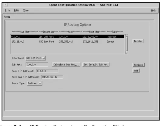
IP Routing Options
This window (Figure 3-4) lets you configure IP Routing options that the unit can support as described in the pages that follow.
Agent Configuration 3-9
Figure 3-4 IP Routing Options Agent Configuration Window
Fields
Interface –indicates the routing interface type, i.e., GDC LAN Port, GDC WAN Port, LAN/WAN Port.
Sub Net –identifies the network segment on which the target is resident. This field contains the following buttons:
• Calculate Sub Net ... if the selected route is indirect, you may have the system calculate Sub Net. A pop-up opens requesting the IP Address of the target/ destination device. The system ‘ANDs’ the address with the mask to provide the proper Sub Net value. Alternatively, you may enter the valid Sub Net value directly. Note that if you are uncertain of the Sub Net value, use the system to calculate it.
• Set Default Sub Net ... if the route type is direct, then use this to set the Sub Net value. The system ‘ANDs’ the next hop address and the mask to determine the Sub Net.
Mask – is used to divide IP Addresses into network identifier and host identifier. The bits set to ‘1’ in the mask correspond to the network identifier. The entire network identifier portion must be contiguous and to the left of the host identifier portion. Examples appear on the next page.
3-10 Agent Configuration
Next Hop – Specifies the IP Address of the next unit. Route Type – Selects one of the following routing types:
Direct – Signifies that the target device is on the same segment. Indirect – Signifies that the target device is not on the same segment.
SNMP IP Routing (SNMP 540EN DSU Only)
In the IP group of MIB-II there is an IP Routing Table that contains an entry for each route known to the unit. The main function of the table is to equate each out-going IP packet with a route that provides the physical interface port. The routing table can be built via SNMP if there is an existing IP connection to one of the ports. The routing table is stored in volatile memory, and it is lost if the unit is repowered.
Adding an IP Route To add an IP Route:
1. In the IP Routing Options window select an interface type from the Interface field. This mask is the filter used to establish the Routing Table. It must be set
by experienced system administrative personnel. Some valid subnet masks are:
255.0.0.0 Standard Class A network mask 255.128.0.0 Class A network, 2 subnetworks 255.192.0.0 Class A network, 4 subnetworks 255.224.0.0 Class A network, 8 subnetworks 255.255.0.0 Standard Class B network mask 255.255.128.0 Class B network, 2 subnetworks 255.255.192.0 Class B network, 4 subnetworks 255.255.224.0 Class B network, 8 subnetworks 255.255.255.0 Standard Class C network mask 255.255.255.128 Class C network, 2 subnetworks 255.255.255.192 Class C network, 4 subnetworks 255.255.255.224 Class C network, 8 subnetworks
Subnet mask IP Address Network Ident Host Ident 255.255.255.0 192.9.200.100 192.9.200.0 100 192.9.200.200 192.9.200.0 200 255.255.255.128 192.9.200.200 192.9.200.0 200 255.255.255.128 192.9.200.100 192.9.200.0 100 192.9.200.200 192.9.200.128 72 255.255.255.192 192.9.200.100 192.9.200.64 36 192.9.200.200 192.9.200.192 8 NOTE
Agent Configuration 3-11
2. Click the pointer in the Mask (IP Address) and when the cursor appears enter an IP Ad-dress.
3. In the Sub Net field enter the appropriate address.
To calculate a Sub Net value you may use the Calculate Sub Net... button. To Set the default you may the Set Default Sub Net.
4. Click the pointer in the Next Hop field and when the cursor appears enter the address of the next hop.
5. Select the appropriate route type from the Route Type field. 6. Click on the Add button.
7. Select Save to Unit from the File menu. Editing an IP Route
To edit an IP Route:
1. In the IP Routing Options window select the item that you want to edit.
The IP Routing information of the selected item appears in the fields below the display. 2. Perform the desired changes.
3. Click on the Replace button.
4. Select Save to Unit from the File menu. Deleting an IP Route
To delete an IP Route:
1. In the IP Routing Options window select the item that you want to delete.
2. Either click on the Delete button or select Invalid in the Status field and then click on the Replace button.
Introduction
The TEAM 540 controller application consists of a group of smaller applications, each devoted to a specific aspect of controlling or monitoring SNMP 540 and SNMP 540EN DSUs. There are two means of access to the TEAM 540 applications: the map window menu bar, and the Front Panel window Select button menus. This chapter describes both. It also fully describes the Information function, which is accessed through the Front Panel display and displays a read-only window to identify the revision level of the TEAM 540 application software.
There are three applications in the Performance category of both menus: Alarm Detail displays alarm information in a read-only window, Line Statistics displays information about the network interface, DTE Status displays the status of signals in the DTE interface. The map window Performance menu also includes a selection for launching the Front Panel displays. This chapter fully describes all four applications.
There are two applications in the Configuration category: Configure and Maintenance. Each supports read/write windows by which you can review and alter unit operating parameters. This chapter describes how to access the Configure and Maintenance applications. Instructions for using the two applications appear in subsequent, individual chapters.
The Diagnose application supports one read/write window by which you can command test functions of the units and view results of each test as it is completed. It also supports a read-only Diagnostic History window that displays the results all tests conducted during a diagnostic session. This chapter describes how to access the Diagnose application. Instructions for using the application appear in a subsequent chapter.
TEAM 540 Access
In order to work with the TEAM 540 applications you must first launch HP Openview. Within the Openview system, icons for all TEAM-managed standalone devices are grouped together in a submap identified as the TEAM Standalone Universe.
The icon for the Standalone Universe submap that appears in the Openview Root map consists of the GDC logo and the word TEAM enclosed in a circle; the title below the icon is Standalone. When you double click on the Standalone icon the resulting submap displays icons for the individual managed devices.
To access TEAM 540 functions you can either select a device icon in the submap and then select from the submap window menus, or double click on a device icon to open the Front Panel display for the device. The Front Panel display provides Select button menus for access to the TEAM functions.
Map Window Menu Bar Access
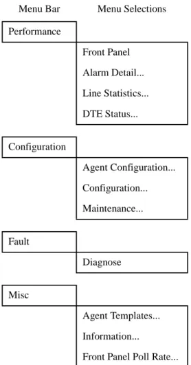
The table on the following page illustrates how the TEAM 540 application functions are arranged on the menu bar at the top of the Standalone Universe submap window. The table shows only the menu selections for the TEAM 540 applications. The map window menus include selections in addition to those that apply to TEAM 540 because the window also provides access to other applications.
4-2 Operations
The Performance menu Front Panel selection opens the Front Panel display window. The Select button menus in the Front Panel display window include the selections that appear above, with the exceptions of Front Panel in the Performance menu and all three items in the Misc menu.
SNMP 540 Front Panels
The SNMP 540 Front Panel display windows provide graphical interface to a selected DSU. To launch a Front Panel, either select the unit you intend to work with in the HPOV Map window, then select Front Panel from the Performance menu for that window; or double click on the unit icon in the map window.
The application responds by displaying a window that depicts the front panel of the selected unit: • SNMP 540 IFP DSU, shown in Figure 4-1
• SNMP 540EN DSU, shown in Figure 4-2
Figure 4-1 SNMP 540 IFP DSU Front Panel
Menu Bar Menu Selections Performance Front Panel Alarm Detail... Line Statistics... DTE Status... Configuration Agent Configuration... Configuration... Maintenance... Fault Diagnose Misc Agent Templates... Information...
Operations 4-3
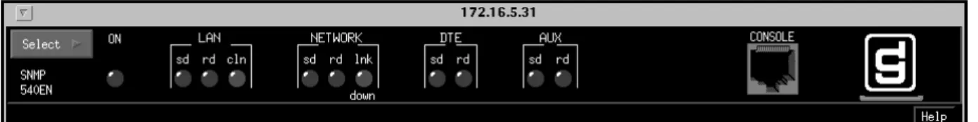
Figure 4-2 SNMP 540EN DSU Front Panel
The LEDs shown in a Front Panel display reflect the states of the actual indicators on the physical unit. The complement of indicators displayed for the two models of DSU differ sharply. The SNMP 540 IFP DSU Front Panel display contains the following indicators:
NS – No Signal indicates when lit that the DSU is not receiving a DDS signal SD – Send Data indicates when lit that the DSU is transmitting data
RD – Receive Data indicates when lit that the DSU is receiving data RS – Request To Send indicates when lit that RTS from the DTE is active
CS – Clear To Send indicates when lit that the DSU is outputting CTS to the DTE CO – Carrier On indicates when lit that the DSU is receiving a usable signal from the network
TR – Terminal Ready indicates when lit that Data Terminal Ready from the DTE is active NORM – indicates when lit that the DSU is in operating mode, when Off the DSU is in test mode
TEST/OK – indicates when flashing that errors were detected during a test DBU – indicator not currently supported
SNMP CO – indicates when lit that the DSU is receiving valid IP frames on the management channel
SNMP DATA – indicates when lit that the DSU is receiving a message on the management channel
SNMP RESP – indicates when lit that the DSU is sending a message on the management channel
SNMP TEST – indicates when lit that the DSU is performing a test initiated by an SNMP command
The SNMP 540EN DSU Front Panel display contains the following indicators: ON – indicates when lit that the DSU is connected to power and functioning
LAN sd – LAN Send Data, indicates when lit that the DSU is sending management data on the Local Area Network
LAN rd – LAN Receive Data, indicates when lit that the DSU is receiving management data on the Local Area Network
LAN cln – LAN Collisions, indicates when lit that collisions are occurring on the Local Area Network, slowing the exchange of management data
NETWORK sd – Network Send Data, indicates when lit that the DSU is sending data on the Telco network
NETWORK rd – Network Receive Data, indicates when lit that the DSU is receiving data on the Telco network
NETWORK lnk down – Network Link Down, indicates when lit that the DSU does not have an active connection to the Telco network, when the DSU is in a test mode this indicator displays a two-headed, up/down arrow
DTE sd – DTE Send Data, indicates when lit that the DSU is receiving data from the DTE to transmit
4-4 Operations
DTE rd – DTE Receive Data, indicates when lit that the DSU is passing received data to the DTE
AUX sd – Auxiliary Send Data, indicates when lit that the DSU is sending management data through its back panel Auxiliary port
AUX rd – Auxiliary Receive Data, indicates when lit that the DSU is receiving management data through its back panel Auxiliary port
The application polls the unit to keep the states of the LEDs in the Front Panel display current. The time of the most recent poll appears in the bottom left corner of the Front Panel display. The time is displayed in white when Auto Poll is enabled, and in yellow when it is disabled.
The Select button, in the upper left corner of the Front Panel displays, provides access to menus for the rest of the TEAM 540 application functions. The following table shows the arrangement of the Select button menus. It differs somewhat from the arrangement on the Map window menu bar.
Select Menu Items Menu Selections Performance Alarm Detail... Line Statistics... DTE Status... Configuration Agent Configuration... Configuration... Maintenance... Fault Diagnostics... Demand Poll Auto Poll (*) 15 seconds 30 seconds 60 seconds Disable
Operations 4-5
The two Poll selections in the Select button menu determine when the application collects new information from the unit to update the Front Panel window:
• Selecting Demand Poll causes an immediate update of the display.
• Auto Poll enables you to select updates at 15, 30, or 60 second intervals, or to disable automatic polling. If you select Disable, the Front Panel window displays a static snapshot of the LED states as they were at the last poll, either when the window was launched or a subsequent Demand Poll.
Each time the Front Panel display is opened, its initial polling rate is determined by the Front Panel Poll Rate selection of the HPOV map window Misc menu.
The menu selection Exit dismisses the Front Panel window when you click on it.
Performance Functions
Alarms
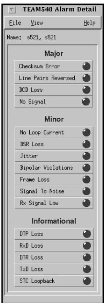
You can launch the TEAM 540 Alarm Detail application from the HPOV Map Performance Menu or from the front panel menu. The application displays the read-only Alarm Detail window for the selected unit (See Figure 4-3).
The TEAM 540 application gets alarm indications from the unit in two ways:
• By receiving traps sent automatically in response to alarm conditions at the unit • By polling the unit for changes in alarm conditions
4-6 Operations
The Alarm Detail window displays alarms grouped into three categories:
• Major
• Minor • Informational Major Alarms
Checksum Error – indicates that the non-volatile memory that stores the unit configuration has become corrupted
Line Pairs Reversed – indicates that the transmit and receive line pairs are reversed DCD Loss – indicates that the unit is not receiving usable carrier signal from the network No Signal – indicates that the unit is not connected to a DDS signal
Minor Alarms
No Loop Current – indicates that network sealing current is inadequate or absent DSR Loss – indicates loss of Data Set Ready
Jitter – indicates that jitter on the Telco line exceeded its configured threshold for at least one alarm interval
Bipolar Violations – indicates that the number of violations received by the unit exceeded its configured threshold for at least one alarm interval
Frame Loss – indicates that the number of DDS-II framing losses detected by the unit exceeded its configured threshold for at least one alarm interval
Signal To Noise – indicates that the signal to noise ratio on the Telco line was below its configured threshold for at least one alarm interval
Rx Signal Low – indicates that the signal level received on the Telco line remained below its configured threshold for at least one alarm interval
Informational Alarms
DTP Loss – indicates loss of Data Terminal Power (SNMP 540 IFP DSU only) RxD Loss – indicates loss of Receive Data
DTR Loss – indicates loss of Data Terminal Ready TxD Loss – indicates loss of Transmit Data
STC Loopback – indicate that the Telco Serving Test Center (STC) initiated a test on the line Alarm Detail Window Menus
The Alarm Detail window has a File menu and a View menu in its menu bar.
The File menu contains only the selection Exit, by which you can dismiss the window.
The View menu consists of three selections: Major, Minor, and Informational, each with a check box beside it. To remove an alarm category from the window display, click on its check box so that it is unchecked. Clicking a box so that it is checked restores the corresponding category to the display.
Operations 4-7
Line Statistics
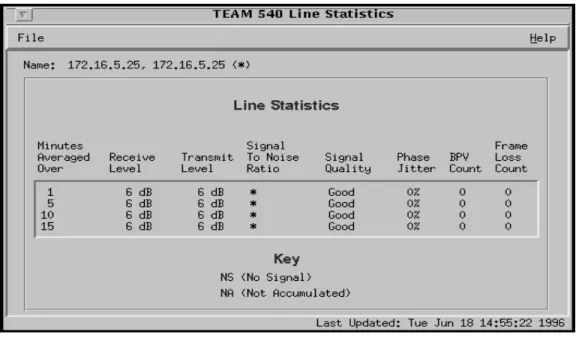
You can launch the TEAM 540 Line Statistics application from the Performance Menu of the HPOV Map or the front panel Select button. As shown in Figure 4-4, the application displays seven categories of line performance statistics accumulated by the unit. The four lines of the display show the results of averaging performance values over the most recent 1 minute, 5 minutes, 10 minutes, and 15 minutes.
Figure 4-4 Local Reports Window Line Statistics Window Menus
The Line Statistics window has a File menu that consists of Refresh and Exit selections. The Refresh selection causes the window to display the latest available data. The window is not a dynamic display, so you should use the Refresh selection occasionally when you keep the window open for long periods. The Exit selection dismisses the Line Statistics window.
DTE Status
You can launch the TEAM 540 DTE Status application from the HPOV Map Performance Menu or from the front panel menu. The application displays a read-only Status window for the selected DSU. The window displays indicators for the states of the EIA signals at the DTE interface. Dark green indicates Off, light green indicates On, and light green with a superimposed two-headed arrow indicates transitions.
The displayed window varies depending on whether the selected unit is an SNMP 540 IFP DSU (See Figure 4-5) or an SNMP 540EN DSU (See Figure 4-6). The window displayed for an SNMP 540EN DSU does not include the Data Terminal Power (DTP) item that appears in the window for the SNMP 540 IFP DSU.
Status Window Menu
The Status window has a File menu in its menu bar with the selections Demand Poll, Auto Poll, and Exit.
4-8 Operations
Auto Poll enables you to select updates at 15, 30, or 60 second intervals, or to disable automatic polling. If you select Disable, the Status window displays a static snapshot of the EIA indicators as they were at the last poll, either when the window was launched or a subsequent Demand Poll. The time of the most recent poll appears in the bottom left corner of the window. The time is displayed in white when Auto Poll is enabled, and in yellow when it is disabled.
Figure 4-5 SNMP 540 DSU DTE Status Window
Operations 4-9
Configuration Functions
Configuration
You can launch the TEAM 540 Configuration application from the HPOV Map Configuration Menu or from the front panel menu.
When you launch the application, it initially displays the read-only TEAM 540 Configuration window, which has a File menu and a Navigate menu in its menu bar.
The File menu contains the selections
• Refresh, which discards all unsaved changes and restores all options in the displayed configuration windows to the values they are assigned by the current operating configuration
• Save to Unit, which puts the new configuration into use by the unit
• Load Template, by which you can recall a stored configuration template that you can then save to the unit either with or without modifications
• Save to Template, by which you can store the current configuration on the workstation for future use as a template
• Compare to Template, by which you can identify differences between the configuration displayed on-screen and a selected template
• Exit, by which you can dismiss the window.
The Navigate menu enables you to access, singly or all at once, the read/write windows by which you can configure various aspects of DSU operation:
• DDS Options • DTE Options • Alarms Reported
The TEAM 540 Configuration application is fully described in Chapter 5, Configuration.
Maintenance
You can launch the TEAM 540 Maintenance application from the HPOV Map Configuration Menu or from the front panel menu.
The application displays one read/write window by which you can control some aspects of operation that fall outside the scope of Configuration. The TEAM 540 Maintenance application is fully described in Chapter 6, Maintenance.
Diagnostics
You can launch the TEAM 540 Diagnostics application from the Fault Menu of the HPOV Map or the Front Panel display Select button.
The application displays one read/write window by which you can control a variety of test functions on a selected DSU. The TEAM 540 Diagnostics application is fully described in Chapter 7, Diagnostics.
4-10 Operations
Miscellaneous Functions
There are two functions that appear on menus under the category Misc: Information and Local Reports.
Information
You can launch the TEAM 540 Information window in three ways: • from the HPOV Map Misc menu
• from the Front Panel display Select button Misc menu
• by double clicking on the GDC logo in the Front Panel display
Information displays one read-only window that contains the name of the application, software revision level information, and copyright information. The File menu in the menu bar contains only the selection Exit, by which you can dismiss the window.
Figure 4-7 TEAM 540 Information Window
Front Panel Poll Rate
You can open the Front Panel Poll Rate window (See Figure 4-8) from the HPOV shelf submap Misc Menu. The setting you select in this window determines the initial polling rate for Front Panel displays each time they are opened.
The rate selection is a global function. It selects initial polling rate for all front panel displays linked to a TEAM Core application, regardless of which individual application you access it from.
There are four selections, each accompanied by a checkbox: Slow
Normal Fast
Demand Poll Only
The File menu in the menu bar contains two selections: Save to File and Exit.
To set the desired polling rate, first click on the appropriate checkbox and then select Save to File from the File menu. The precise polling frequency that results from a setting of Slow, Normal, or Fast depends on a number of factors. The higher the rate, the more communication and processor capacity is devoted to maintaining the display.
Operations 4-11
by means of the Auto Poll selection in the Select button menu. Changes you make with that menu selection are not retained when the display is closed.
To dismiss the window, select Exit from the File menu.
Introduction
The TEAM 540 Configuration application enables you to set all the options in an SNMP 540 IFP DSU or an SNMP 540EN DSU through a convenient group of configuration windows.
To Start TEAM 540 Configuration
You can start the TEAM 540 Configuration application by either of two methods:
• Select a DSU symbol on the submap in OpenView, then select the Configuration option from the Configuration menu.
• Click on the Select button of the Front Panel display, then click on Configuration and select Configuration from the resulting menu.
Templates
You can store configuration settings as templates on the workstation that runs the TEAM 540 application. A template stores a configuration for the unit options, and you can store as many templates as you need.
To load configuration settings from a template into the DSU you must perform the following steps:
1. Select Load Template from the File menu and select the template from the resulting dialog window. The application retrieves the configuration settings of the selected template. 2. Select Save to Unit from the File menu. The application makes the template configuration
settings the current operating configuration for the unit.
Configuration Procedure
The following steps describe how to use the configuration application, and illustrate the functions of the Main Configuration window menus.
1. Access the Main Configuration window, either from the submap or from the Front Panel display. The application reads the current Main configuration from the unit when you open the Main window.
You can select to base your configuration changes on either the current configuration or a stored configuration template. In either case, the unit continues to operate using its unchanged current configuration.
The Refresh selection on the Main window File menu causes the application to read the current configuration from the unit. All changes to all configuration windows that have not previously been saved to the unit or to a template are lost when you select Refresh. 2. To edit the current configuration of the unit, proceed directly to the Navigate menu as
de-scribed below.
5-2 Configuration
To edit a template, select Load Template from the File menu and select a template from the resulting list.
3. Click on the Navigate button to display a menu of the configuration windows, and select the one in which you intend to make changes.
4. Make changes as needed in the configuration window. When you click on the input field for an option, a window opens to display all the values the field can be set to. Click the mouse on the value you select. When you change the value or setting of an option, the ap-plication displays the option name and the new value in white, rather than black, type. They remain white until you either save the changes to the unit or a template by means of the Main window File menu, or restore the option to its last stored value or setting.
You can discard changes to a configuration window and return all its fields to their stored values in two ways:
• Click on the Reset button to discard changes while keeping the window open
• Click on the Cancel button to discard changes and close the window. You can close a configuration window without losing changes by clicking on either the OK
button or the pushpin icon, which is located in the upper left corner of the window.
You can keep multiple configuration windows open on-screen and move between them by clicking the mouse on the one in which you intend to operate. The Main Configuration window remains on-screen throughout the configuration process.
5. When you have accessed all the configuration windows that you need to and made all of your changes, click on the File menu button of the Main Configuration window. From that menu you can select Save to Unit to save the new configuration in the unit, or select Save
to Template to save it as a template in the workstation.
6. When you select Save to Unit, the changed configuration becomes the current configura-tion for the DSU you are configuring.
7. When you select Save to Template, a window appears containing a list of existing templates and a field for entering a new template name. You can select an existing template to be overwritten with the new configuration, or enter a name to create a new template. A stored template is available to be loaded by the application and then saved, with or without further modification, to any unit of the same type.
Configuration Option Values
When you click the mouse on the entry field for a configuration item, a window opens containing all the values that are permitted for that configuration item. Hold down the mouse button until the highlight is on the value you intend to configure, then release the button. The newly selected value appears in the entry field for the configuration item.
Main Configuration Window
The Main Configuration window has two pull down menus, File and Navigate, that are the means by which you carry out the actual process of configuring the selected unit. From the Navigate
menu you select the individual configuration windows in which you make changes. The File menu commands the storage and retrieval of configuration settings. The contents of the two
Configuration 5-3
The Main Configuration window title bar displays the application name, TEAM 540
Configuration. The main body of the window contains items that identify the selected unit and provide information about its operations.
Main Configuration Window Fields
The Main Configuration window displays the following items under the three headings System Information, Channel Interface, and MIB Versions:
System Name configurable field to specify and display the name assigned to the selected DSU
System Location configurable field to specify and display the site at which the selected DSU is located
System Contact configurable field to specify and display the name of a contact person responsible for the selected unit
System Up Time read-only field, displays elapsed time since the unit was last powered-up
System Description read-only field, identifies the model of the selected unit
Serial Number read-only field, displays the serial number of the selected unit
GDC-DDS MIB Version read-only field, displays revision level of the GDC DDS MIB for network interface functions
GDC-SNMP540 MIB Versionread-only field, displays revision level of the product-specific
GDC SNMP 540 MIB
GDC-CMN MIB Version read-only field, displays revision level of the GDC Common MIB
Menu Buttons Menu Selections Further Selections File
Refresh Save to Unit
Load Template dialog window Save to Template dialog window Compare to Template dialog window Exit Navigate DDS Options... DTE Options... Alarms Reported... All Screens...
5-4 Configuration
The TEAM 540 application relies on the DSU to indicate when a configuration problem has caused an SNMP set error.
Configuration
To configure the read/write fields of the Main Configuration window:
1. Click the pointer in the System Name field. When the cursor appears, enter the name you are assigning to the unit being configured.
2. Click the pointer in the System Location field. When the cursor appears, identify the site at which the unit is located.
3. Click the pointer in the System Contact field. When the cursor appears, enter the name and/ or telephone number of the person to be contacted in case of a problem with the unit.
Figure 5-1 Main Configuration Window
DDS Options
The TEAM 540 DDS Options window (Figure 5-2) lets you define the network interface of the selected unit.
Configuration 5-5
Figure 5-2 DDS Options Window
Buttons
OK - dismisses the window while retaining the changes you have made. The changes are not
stored permanently until you perform a Save to Unit or Save to Template at the Main Configura-tion window.
Reset - replaces the information in the fields with the most recently read information from the
unit. Note that this button does not initiate a read of information from the unit.
Cancel - dismisses the window and cancels unsaved changes.
Options
Line Type - selects the unit line type.
Options:
DDS standard DDS-I service
DDS /sc DDS-II service (DDS with secondary channel)
Auto Bauding read-only indication that appears if you open the window while the unit is determining the line type; should change to one of the other three options when you click the Refresh button after determination is complete. This selection applies to the SNMP 540 IFP DSU only.
Clear Channel read-only indication that is displayed when the Admin Data Rate option is set to 64Kbps
Admin Data Rate - selects the data rate for the unit
Options:
Auto Sync unit adapts to the rate of incoming signals. This selection applies to the SNMP 540 IFP DSU only.
56Kbps 64Kbps
5-6 Configuration
Tx Clock Source - selects the transmit clock source for the DSU.
Options:
Receive transmit timing derived from the received signal Internal transmit timing generated by the DSU
External transmit timing supplied by the DTE
External Buffer Clock - selects whether or not a buffer is used in the transmit data path to
com-pensate for clock jitter or frequency mismatches when external transmit timing is used Options:
Internal disables buffer, use with Receive or Internal timing External enables buffer, use with External timing
Circuit Assurance - when enabled causes the DSU to clamp Clear To Send in response to Idle,
Out of Service, or No Signal conditions, or when it receives an Abnormal Station or Inactive Channel code
Options: Enable Disable
System Status - when enabled causes the DSU to clamp Data Set Ready in response to Idle, Out
of Service, or No Signal conditions, or when it receives an Abnormal Station or Inactive Channel code
Options: Enable Disable
Termaloop - selects loopback termination mode
Options:
Enable line loopback is not permitted
Configuration 5-7
DTE Options
The TEAM 540 DTE Options window lets you define the DTE interface for the unit. There are two variations of this window, one displayed when an SNMP 540EN DSU is selected (see Figure 5-3) and one displayed when an SNMP 540 IFP DSU is selected (see Figure 5-4). In each window the options are arranged under three labels, the first two of which are Control Parameters and EIA Control Parameters. The third label on the window is Aux Port Parameters when an SNMP 540EN DSU is selected, and Interface Parameters when an SNMP 540 IFP DSU is selected.
5-8 Configuration
Figure 5-4 TEAM 540 DTE Options Window – SNMP 540 IFP DSU
Buttons
OK - dismisses the window while retaining the changes you have made. The changes are not
stored permanently until you perform a Save to Unit or Save to Template at the Main Configura-tion window.
Reset - replaces the information in the fields with the most recently read information from the
unit. Note that this button does not initiate a read of information from the unit.
Cancel - dismisses the window and cancels unsaved changes.
Options
Control Parameters
CTS Delay - selects delay between Request To Send from the DTE and Clear To Send returned
by the DSU. The delay permits the DSU time to establish a reliable communication link before transmitting data. It is normally not required for a point-to-point application.
Options:
On forces both RTS and CTS to remain constantly On
3 Characters selects a delay equal to the time required to transmit 3 characters 0 selects no delay
30 selects a delay of 30 msec 60 selects a delay of 60 msec 90 selects a delay of 90 msec
Configuration 5-9
Local DSR - selects the conditions under which the DSU outputs Data Set Ready to the DTE
Options:
Follows DTR the DSU outputs DSR in response to Data Terminal Ready received from the DTE
Forced On the DSU maintains DSR constantly On
Analoop DSR - selects the state of Data Set Ready during an Analoop (line loop) test
Options:
Off the DSU does not output DSR during the test; use of a test signal from the DTE is pre-vented
Normal the DSU controls DSR as selected by the Local DSR option
Tx Carrier - selects between constant and switched transmit carrier operation
Options:
Constant transmit carrier is on at all times; usually selected for point-to-point applications and master site in multidrop applications
Switched transmit carrier is controlled in response to RTS from the DTE; usually selected for remote site in multidrop applications
Rx Carrier - selects between constant and switched receive carrier operation
Options:
Constant receive carrier is on at all times; usually selected for point-to-point applications and remote site in multidrop applications
Switched receive carrier is usually selected for master site in multidrop applications EIA Control Parameters
Test Mode Control - selects whether or not the DSU outputs a Test Mode indication to its DTE
while performing diagnostic functions Options:
Allow DSU outputs Test Mode indication
Block DSU does not output Test Mode indication
RL Test Control - selects whether or not the DTE can command the DSU into a Remote Loop
test by turning on an interface lead Options:
Allow DTE can command Remote Loop Block DTE cannot command Remote Loop
LL Test Control - selects whether or not the DTE can command the DSU into a Local Loopback
test by turning on an interface lead Options:
Allow DTE can command Local Loopback Block DTE cannot command Local Loopback
5-10 Configuration
Aux Port Parameters (SNMP 540EN DSU)
Aux Port Speed - selects the operating rate for the back panel Auxiliary port used for
manage-ment channel data on the SNMP 540EN DSU Options: sync - External 115.2K 57.6K 38.4K 19.2K 9.6K 4.8K 2.4K
Interface Parameters (SNMP 540 IFP DSU)
Interface Type - specifies the type of interface in use for management channel data at the back
panel Auxiliary port on the SNMP 540 IFP DSU Options:
RS232 V.35
Auto unit senses and adapts to interface type in use
Alarms Reported
The TEAM 540 Alarms Reported window (Figure 5-4) lets you designate the alarms that are to be masked (not reported) or unmasked (reported).