OMX-RS232 Control Interface
Description
• Integrates GRAFIK 5000/6000/7000 Systems with a touchscreen or other digital equipment that supports RS232 communication.
• Provides RS232 monitoring commands that allow a touchscreen to query GRAFIK Systems to:
– Determine which scene is selected. – Keep track of buttons pressed.
• Provides RS232 control commands that allow a touchscreen to operate GRAFIK Systems to: – Select or sequence lighting scenes.
– Raise or Lower one or more zones. – Lock lighting controls.
– Activate panic mode (lights go to full on). • Functionality is setup via the GRAFIK System
Processor Panel.
Function
Zone Lock Retain
Scene Lock Retain
Sequence Retain
Sequencing Scene Range
Multiple OMX-RS232 Addresses
Button Feedback
Scene Status
When Activated
If power goes out, locked zones stay locked when power returns.
If power goes out, locked scenes stay locked when power returns.
If power goes out, sequencing resumes when power returns.
Sequencing loops through scenes 5 to 16.
DIP Switches 1-4 used to set address, not function.
Interface reports Control Unit and Wallstation button presses.
Interface reports scene changes.
When Otherwise
Power cycling unlocks locked zones.
Power cycling unlocks locked scenes.
Power cycling stops sequencing.
Sequencing loops through scenes 1 to 4.
DIP Switches 1-4 operate as specified above.
No reporting on button presses.
No reporting on scene changes.
Functions
Power
Low-voltage Class 2 (PELV).
Operating Voltage: 32 V Direct Current.
Basic RS232 Command Set
Monitoring: Scene selection and scene status updates.
Control: Scene selection, scene lockout, sequencing, zone lockout, zone raise/lower.
System Communications and Capacity
• Low-voltage Class 2 (PELV) wiring connects OMX-RS232 Interface to Processor Panel. • Multiple OMX-RS232 Control Interfaces may be used.
• 50 ft. (15m) maximum from OMX-RS232 Interface to PC or other RS232 source.
Environment
32-104°F (0-40°C). Relative humidity less than 90% non-condensing.
Specifications
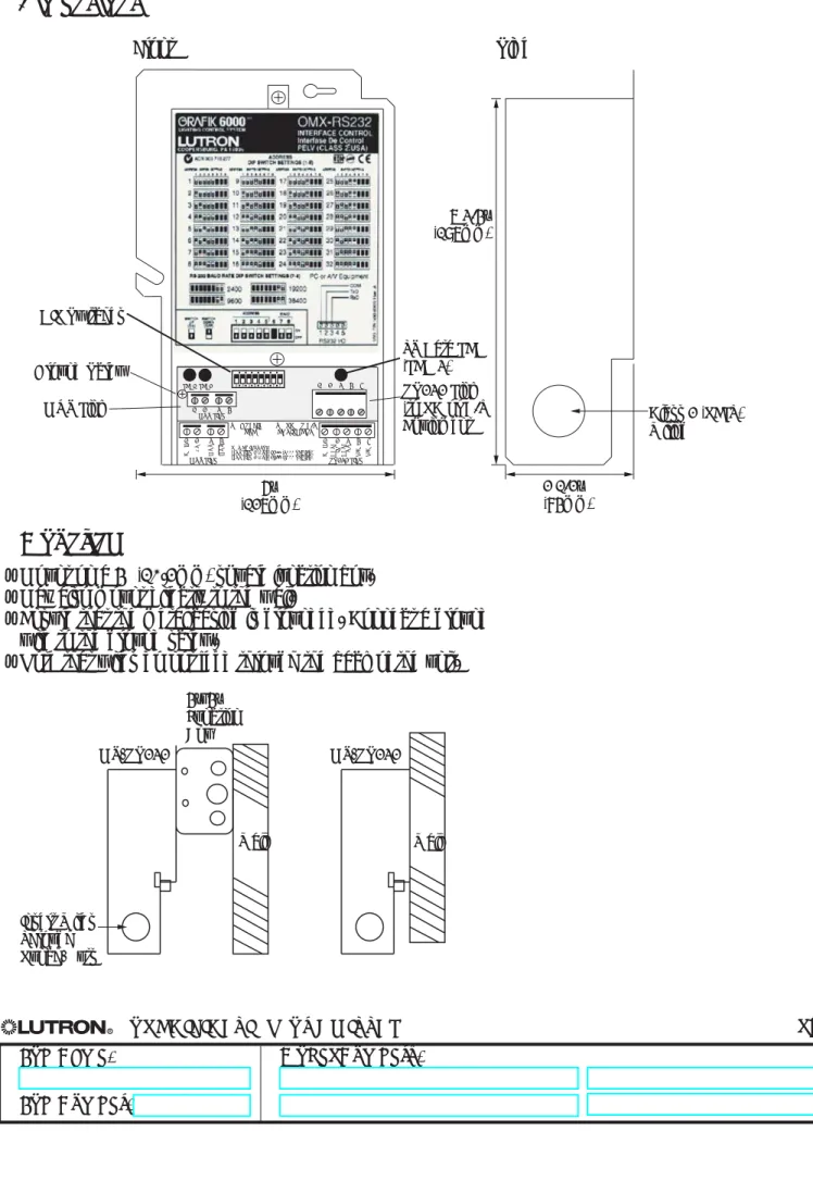
Dimensions
Front Side MUX LINK 1 2 3 4 1 2 3 4 5 6 7 8 LED1 LED2 1 RS232 INTERF ACE AUXILIAR Y CONTROL GRX-RS232 COOPERSBURG, PA 18036 R 1 2 3 4 5 6 7 8 ZONE LOCK RET AIN SCENE LOCK RET AIN SEQUENCE RET AIN SEQUENCE TYPEFIXED ADDRESS ON: DIPSWITCHES 1-4 FOR ADDRESSING
OFF: ONLY ONE INTERFACE PER LINK RAW FEEDBACK
SCENE ST ATUS TIMECLOCK
ZONE LOCKED UNITS WILL REMAIN IN ZONE LOCK AFTER A POWER OUT AGE SCENE LOCKED UNITS WILL REMAIN IN SCENE LOCK AFTER A POWER OUT AGE SEQUENCING UNITS WILL AGAIN SEQUENCE AFTER A POWER OUT AGE ON: SEQUENCE SCENES 5-16 OFF: SEQUENCE SCENES 1-4
INTERF ACE WILL REPOR T WHEN A BUTTON
HAS BEEN PUSHED OR RELEASED ON A
GRAFIK EYE MAIN UNIT OR ACCESSORY INTERF ACE WILL RETURN THE CURRENT SCENE OF ALL MAIN UNITS WHEN A NEW SCENE IS SELECTED
SWITCH FUNCTION DESCRIPTION
GRAFIK Eye 3000 Series
FOR WIRING OF 4000 SERIES, REFER TO INST ALLATION INSTRUCTIONS
1 2 3 4 MUX LINK 1 2 3 4 5 RS232 LINK PC OR A/V EQUIPMENT RxD TxD COM DTR +V DTR -V HOT/LIVE SSA Zone 3 Zone 2 Zone 1 CU WIRE ONL Y Neutral Class 2 4 3 2 1 For use with Lutron GRAFIK Eye 3000 and 4000 products only. CLASS 2 /SELV R 2 3 4 5 TO PC OR A/V EQUIPMENT TO GRAFIK EYE
MUX LINK RS232 LINK
1 2 3 4 5 1 2 3 4 CO M +V MU X MU X CO M DA T A IN DA T A OUT N/C N/C POWER INPUTS:
MUX LINK 2 (+V): 12 (3000 SERIES) MUX LINK 2 (+V): 24 (4000 SERIES)
DIP Switches MUX Link 6” (127mm) TX Data LED (LED 3) RS232 Link (to PC or A/V
Equipment Class 2 (PELV)Wiring 7 3/4”
(197mm)
2 1/2” (84mm) Ground Screw
• Mount on a 4" (10.2mm) square junction box. • May also mount directly to the wall.
• Ensure that the metal casing is grounded. Connect a ground wire to the ground screw.
• Note that wires do not feed through the back of the unit.
OMX-RS232 4”x4” Junction Box Insert Wires Through Punch-Outs Wall OMX-RS232 Wall
Mounting
1 2 3 4
RS232 Link 1 2 3 4 5 MUX Link
To additional Wallstations/Control Interfaces. 50 ft. (15m)
Maximum
OMX-RS232 Wiring Terminals COM TxD RxD PC or AV Equipment To Processor Panel
RS232 Link Wiring
• Use cable provided.• Standard 9-pin serial connector plugs into RS232 equipment, other end connects to RS232 Link terminals.
• Must be 50 ft. (15m) or less. RS232 Signals OMX-RS232 Link Terminal 1 2 3 4 5 Signal Common Data In Data Out No Connect No Connect Typical PC or A/V Equipment Com TxD RxD
Pin on 9-pin Cable
5 3 2
• Daisy-chain the OMX-RS232 Interface to the Class 2 (PELV) Wallstation Link that connects to the Processor Panel.
• Make daisy-chain connections to the low-voltage Class 2 (PELV) MUX Link terminals on the front of OMX-RS232 Interface.
• Do not use T-taps. Run all wires in and out of terminal block. • Each terminal accepts up to two #18 AWG (1.0mm2) wires.
• LED 1 lights when the Class 2 (PELV) MUX link is installed correctly. • Consult Processor Panel Specification Submittal for more details.
Low-Voltage Class 2 (PELV) Wiring
Lutron Cable GRX-CBL-46L
MUX LINK 1 2 3 4 1 2 3 4 5 6 7 8 LED1 LED2 1 2 3 4 5 TO PC OR A/V EQUIPMENT TO GRAFIK EYE
MUX LINK RS232 LINK
1 2 3 4 5 1 2 3 4 CO M +V MU X MU X CO M DA T A IN DA T A OUT N/C N/C POWER INPUTS:
MUX LINK 2 (+V): 12 (3000 SERIES) MUX LINK 2 (+V): 24 (4000 SERIES)
Data Link - (1) twisted, shielded pair #18 AWG (1.0mm2) 3: MUX 4: MUX Class 2/PELV Control wiring 1: Common 2: 32VDC D: Drain/Shield (2) #12 AWG (2.5mm2) (2) #12 AWG (2.5mm2) (1) #18 AWG (1.0mm2) (1) #18 AWG (1.0mm2)
• Two #12 AWG (2.5mm2) conductors for common (terminal 1) and 32VDC (terminal 2). These will not fit in terminals. Connect as shown.
• One shielded, twisted pair #18 AWG (1.0mm2) for data link (terminals 3 and 4).
• Connect Drain/Shield as shown. Do not connect to Ground (Earth) or Wallstation/Control Interfaces. Connect the bare drain wires and cut off the outside shield.