Volume 7, Issue 1, Jan-Feb 2016, pp. 97-104, Article ID: IJARET_07_01_012 Available online at
http://www.iaeme.com/IJARET/issues.asp?JType=IJARET&VType=7&IType=1 Journal Impact Factor (2016): 8.8297 (Calculated by GISI) www.jifactor.com ISSN Print: 0976-6480 and ISSN Online: 0976-6499
© IAEME Publication
___________________________________________________________________________
DEVELOPMENT OF MULTI INPUT MULTI
OUTPUT COUPLED PROCESS CONTROL
LABORATORY TEST SETUP
Jignesh PatelAssociate Professor
Instrumentation and Control Engineering Section, Nirma University, Ahmedabad, Gujarat, India
Hasan Vhora
Instrumentation and Control Engineering Section, Nirma University, Ahmedabad, Gujarat, India
ABSTRACT
Multi Input – Multi Output (MIMO) processes are very commonly found in many chemical unit processes. Control of such MIMO processes is always challenging due to coupling between inputs and outputs. Even after very significant efforts made by the research fraternity, control of coupled MIMO process is still an open research issue. Computerized and easy to use laboratory scale set up is very essential to investigate performance of different control algorithm on MIMO process. An attempt is made to develop low cost, configurable, computerized and smaller size multi input multi output coupled process control laboratory test setup. The proposed set up has capability to interface with user friendly LabVIEW platform. With the help of this interface the user can easily deployed any newly developed algorithm and verify on this laboratory scale test set up. The performance of the developed set up is checked with different controller tuning conditions as well with different coupling condition of MIMO process. The performance confirms the functionality of the developed set up.
Keywords: MIMO Coupled Process, PID Control, LabVIEW, Process Control
Cite this Article: Jignesh Patel and Hasan Vhora, Development of Multi Input Multi Output Coupled Process Control Laboratory Test Setup. International Journal of Advanced Research in Engineering and Technology, 7(1), 2016, pp. 97-104.
1. INTRODUCTION
Processes with one input (manipulated) and output (controlled) variable quite a simple problem for control engineering. Such systems are popularly known as Single Input – Single Output (SISO) systems. Many processes do not fit into such simple control definition. Many industrial processes have more than one output as well input variables. For example, rate of production and quality of product. Therefore, there are usually minimum two control loops to deal with. Systems with more than one input and output are known as Multi Input – Multi Output (MIMO) or multivariable system. The most challenging aspect of the control of MIMO systems is the interaction between different inputs and outputs. In general, each input will have an effect on every output of the system.[1, 2] There are few MIMO systems, such that individual input only affects one particular output. These are relatively simple processes to control. These are decoupled MIMO processes. Because of coupling, in MIMO systems, signals interact in opposite way that results in obstacle for designing controller for such system. Classical PID control fails to control such processes, Hence high end control strategies like De-coupler design including two PID controllers , IMC or MPC are needed to be applied [3, 4].
One of the challenges in control education is to have an experimental visualization of the theoretical facts. Appropriate test setups are always needed to show interesting and industrially relevant control problems.[5].. The quadruple tank process has proved to be a very interesting system for control education [6, 7]as interesting properties such as the coupled nature of the plant, the measurable states, [8, 9] the nonlinear behaviour. The main objective behind the development of a laboratory test set up of quadruple tank system is to provide the facility to carry out different control exercises on MIMO system[10]. Some of the possible experiments are listed below.
Control limitations due to interactions, model uncertainties, non-minimum phase behaviour.
Design of decentralized (often called “multi-loop”) controllers, and understand their limitations.
Implement de-couplers to reduce the effect of interactions, and understand their limitations.
Implement a multivariable control solution like Model Predictive Control (MPC).
Compare different control scheme on actual MIMO coupled process.
An effort is made to develop low cost and user friendly test set up, which is capable to check different control algorithm for coupled MIMO system.
The next section provides the details on development of quadruple-tank process set up. Detailed constructional aspects of a quadruple tank process’ apparatus are described along with the LabVIEW interface details. It is important to verify the performance of the proposed system. The third section of the paper presents the control performance of the MIMO system for different settings of the coupling through the adjustment of the valves. Comparative results are presented in the section. Subsequent section of the paper comprises of the discussion on the performance analysis of the system.
2. QUADRUPLE TANK SYSTEM
(a)
(b) (c)
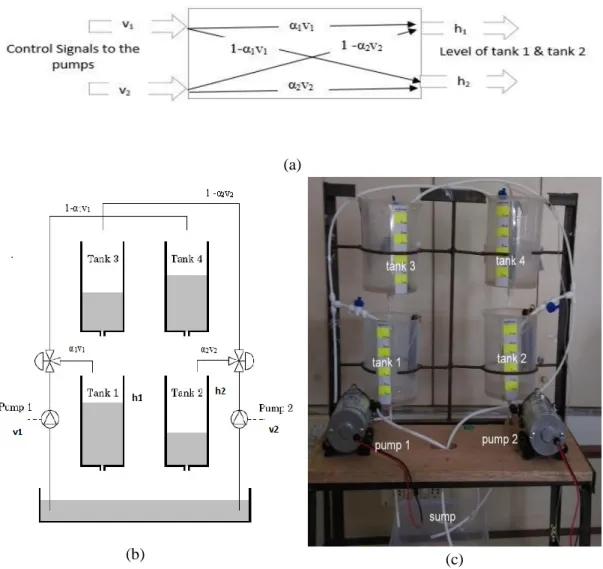
Figure 1 (a) Block diagram of MIMO process (b) schematic diagram of quadruple tank system, (c) actual image of quadruple tank system
Figure 1(a) shows block diagram of the proposed MIMO system. There are two manipulating variables as the DC voltage to the pump. There are two controlled variables as the height of tank 1 and tank 2. Figure 1 (b) shows the schematic diagram for quadruple tank apparatus, the setup consist of four interconnected tanks, two voltage controlled pumps and two three-way valves. Voltage supplied to pumps are considered the inputs to the system while level of lower two tanks are considered outputs of system. This makes it a Multi Input Multi Output system. Two 3-way valves which are employed in this set-up are used to determine the interaction between inputs and outputs. The coupling between two lower tanks can be changed with help of these two valves. Figure 1 (c) shows actual image of the proposed system. Mild steel structure is used to hold up overall system which comprises of plastic beakers, 1/4” piping, extension valves and 24 V DC booster pumps and three way valves. The valve spitting parameters α1 and α2 determines interactions between
two inputs and two outputs for example if α1 = 0.8, 80 % of flow caused by input 1
20% of flow caused by input 1 (supply to pump 1) enters tank 4 which affects output 2 (level of tank 2) causing coupling effect.
Figure 2 Schematic diagram of interfacing of apparatus with LabVIEW
On-chip integrated pressure sensor MPX3V5004G [11] is used to sense the head pressure. The head pressure output is calibrated in terms of level. The sensor provides output in range of 0-5 V DC. It is low cost, reliable, small and easy to install. It does not require any additional signal conditioning circuit. The signals can be directly acquired into LabVIEW [12] using NI 6009 DAQ card [13], NI LabVIEW is used to create a user friendly HMI and as a controller[14]. NI LabVIEW PID and Fuzzy Logic Toolkit for Windows [15] is being used. In order to establish communication between LabVIEW and the set up NI DAQ 6009 is used. This DAQ have adequate amount of digital and analog input/output ports/channels to meet the requirement. In order to properly drive the DC pump, motor driver IC LM298N [16] is used as shown in figure (2). A conventional laboratory DC power supply is employed to supply voltage to hardware setup. Hence a user friendly, reliable, cost effective setup for MIMO process control is prepared.
3. PERFORMANCE ANALYSIS
To confirm the functionality of the developed system, a set of experiments are carried out. Major property of a MIMO system includes presences of coupling between inputs and outputs. Thus, to determine interactions exists and can be manipulated; two simple close loops using PID controller is implemented. Closed loop response of different valve diversion factors [table (1)] and various PID settings [table (2)] are captured and presented.
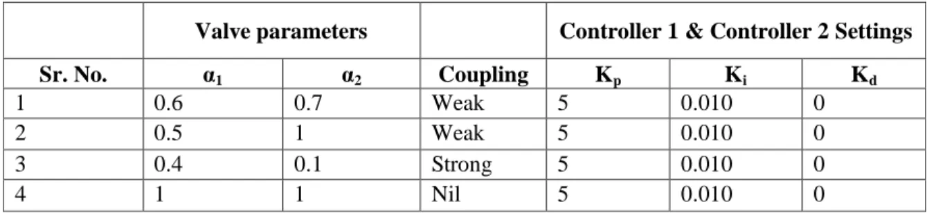
Table 1 Set of parameters for experiment to analyse effect of valve parameter values
Valve parameters Controller 1 & Controller 2 Settings
Sr. No. α1 α2 Coupling Kp Ki Kd
1 0.6 0.7 Weak 5 0.010 0
2 0.5 1 Weak 5 0.010 0
3 0.4 0.1 Strong 5 0.010 0
Table (2) shows set of experiments with different values of α1 & α2 with the same
PID settings. hese experiments help to explore effect of stability due to coupling in the process.
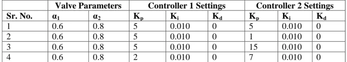
Table 2 Set of parameters for experiment to analyse effect of different PID values Valve Parameters Controller 1 Settings Controller 2 Settings
Sr. No. α1 α2 Kp Ki Kd Kp Ki Kd
1 0.6 0.8 5 0.010 0 5 0.010 0
2 0.6 0.8 5 0.010 0 1 0.010 0
3 0.6 0.8 5 0.010 0 15 0.010 0
4 0.6 0.8 2 0.010 0 7 0.010 0
4. RESULTS AND DISCUSSION
This section covers the discussion on the results obtained for the set of experiments carried out as shown in table (1) and (2). Figure 3 (a) shows an output response for α1
= 0.6 and α2 = 0.8. This is a case of weak coupling [5]. These values of valve
parameter deliver 60 % of flow caused by input 1 (supply to pump 1) enters tank 1 which affects output 1 (level of tank 1) and 40% of flow caused by input 1 (supply to pump 1) enters tank 4 which affects output 2 (level of tank 2) causing coupling effect from input 1 to output 2 and 80 % of flow caused by input 2 (supply to pump 2) enters tank 2 which affects output 1 (level of tank 1) and 20% of flow caused by input 2 (supply to pump 2) enters tank 3 which affects output 1 (level of tank 1) causing coupling effect from input 2 to output 1. Hence, it is seen clearly from graph that set point is being tracked but due to input-output coupling the steady state value reaches the value slight above the set point. Similarly, figure 3 (b) shows response for α1 =
0.5 and α2 = 1 (weak coupling). It has been visualized that level in tank 2 (h2) attains
quickly because of interactions caused by input 1 but level in tank (h1) takes more
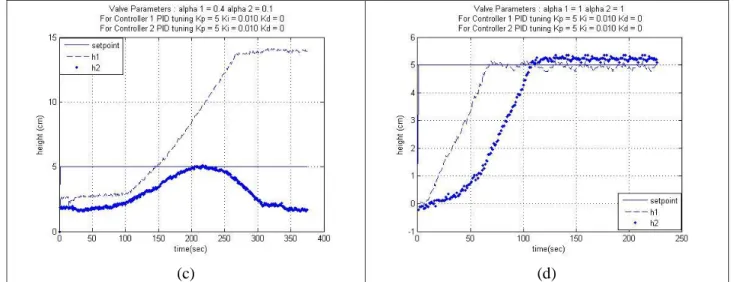
time to track the set point due to coupling effect. Figure 3 (c) shows response for α1 =
0.4 and α2 = 0.1. This setting is considered as strong coupling. As it is shown in
figure, very high amount of input-output coupling is makes system unstable and hence makes tank 1 overflow and tank 2 completely run dry. Figure 3 (d) shows response for α1 = 1 and α2 = 1 (nil coupling). The setting of the valve makes the MIMO process
free from coupling effect. Very good set point tracking for both h1 and h2 is found in
the nil coupling case.
(c) (d)
Figure 3 Output response of system keeping PID parameters constant and Valve parameters (a) α1= 0.6 & α2 = 0.7, (b) α1= 0.5 & α2 = 1, (c) α1= 0.4 & α2 = 0.1, (d) α1= 1 & α2 = 1
Another verification of working of the developed set up is to investigate the effect of different PID controller setting on a MIMO system. As shown in table (2), the interactions of input-output kept same with α1 =0.6 and α2 = 0.8. But, the proportional
gain (Kp), integral gain (Ki) and derivative gain (Kd) are selected as shown in table
(2). Set point tracking performance of four different controller settings are presented in figure 4 (a) to 4 (d) respectively. A MIMO coupled system exhibits property such that if gain of a controller is increased than simultaneously gain of another controller is required to be reduced to maintain overall stability of the system.
(c) (d)
Figure 4 Output response of system keeping valve parameters constant and PID settings (a) Kp1 =5, Kp2 =5, (b) Kp1 = 5, Kp2 =1, (c) Kp1 =5, Kp2 =15, (d) Kp1 =2, Kp2 =7
Figure 4(a) shows that a decent response when controller are tuned to values Kp1
=5 and Kp2 =5; When the controller gain are tuned with Kp1 =5 and Kp2 =1 it is been
observed that the setpoint tracking of level of tank 2 has satisfactory performance but the level of tank 1 could not track the set point. In case of controller tuning with Kp1=5 and Kp2=15 the set point tracking performance is not satisfactory. It clearly
unstable and controlled variable never reaches to set point. Figure 4(d) shows the better control performance with Kp1=2 and Kp2=7. The above discussed set of
experiments well demonstrates the presence of coupling effect between inputs and output.
5. CONCLUSION
A low cost and reliable laboratory set up for mulit input and multi output coupled process control test set up is developed. The PID control algorithm is developed using LabVIEW platform. The user friendly interface has been developed for ease of working with the set up. The process has the enough flexibility to convert it in the SIMO as well MISO process to check the control algorithm performance for such systems. The performance of the test set up is verified with the different PID settings as well with different interaction (coupling) conditions among the inputs and outputs. The result are presented and found in line with the typical behaviour of MIMO process control. The proposed laboratory setup is capable to check and compare the performance of various high end algorithm of multivariable process control.
REFERENCES
[1] Thomas E. Merlin, Process Control Designing Processes and Control Systems for Dynamic Performance, McGraw-Hill Inc., 1995.
[2] Dale E. Seaborg, Thomas F. Edgar , Duncan A. Mellichamp, Process Dynamics and Control, John Wiley & Sons Inc., 2004.
[3] Grebeck, Micheal, A Comparision of Controllers for Quadruple Tank System,” Dept. of Automatic Control, Lund University, Lund, Sweden, 1998.
[4] R. Suja Mani Malar, T.Thyagarajan, Modeling of Quadruple Tank System using Soft Computing Techniques, European Journal of Scientific Research, vol. 29, no. 2, pp. 249-264, 2009.
[5] Alvarado, D. Limon, W. Garc´ıa-Gab´ın , T. Alamo , E.F. Camacho, “An Educational Plant Based on the Quadruple Tank Process, in Int. Federation of Automatic Control, Madriad , Spain, 2006.
[6] Karl Henrik Johansson, Alexander Horchz, Olle Wijkz, Anders Hanssonz, Teaching Multivariable Control Using the Quadruple-Tank Process, in IEEE Conference on Decision and Control, Phoenix, AZ,, 1999.
[7] Johansson, Karl Henrik, The Quadruple-Tank Process: A Multivariable Laboratory Process with an Adjustable Zero, IEEE Transactions On Control Systems Technology, vol. 8, no. 3, pp. 456-465, 2000.
[8] Prof. D. Anggeline Vijula, Anu K, Honey Mol P, Poorna Priya S, Mathematical Modeling of Quadruple Tank System, International Journal of Emerging Technology and Advanced Engineering, vol. 3, no. 22, pp. 261-265, 2013.
[9] Tomi Roinila, Matti Vilkko, Antti Jaatinen, Corrected Mathematical Model of Quadruple Tank Process, in The International Federation of Automatic Control, Seoul, Korea, 2008.
[10] Effendi Rusli, Siong Ang. , Richard D. Braatz, A Quadruple-Tank Process Control Experiment, University of Illinois at Urbana Champaign, 2004. [11] NXP Semiconductors, Datasheet of Integrated Silicon Pressure Sensor,
MP3V5004G,” NXP Semiconductors, [Online]. Available: http://cache.nxp.com/files/sensors/doc/data_sheet/MP3V5004G.pdf?fsrch=1 &sr=3&pageNum=1.
[12] National Instruments, LabVIEW System Design Software, National Instruments, [Online]. Available: http://www.ni.com/labview/.
[13] National Instruments, USER GUIDE NI USB-6008/6009, [Online]. Available: http://www.ni.com/pdf/manuals/371303n.pdf.
[14] National instruments, PID Control, National Instruments, [Online]. Available: http://www.ni.com/white-paper/6440/en/.
[15] National Instruments, NI LabVIEW PID and Fuzzy Logic Toolkit for Windows, National Instruments, [Online]. Available: http://sine.ni.com/nips/cds/view/p/lang/en/nid/209054.
[16] Vaishak Dayanandan and Sudha T, A Novel Antenna for Uwb-Mimo Applications Using A T-Shaped Stub. International Journal of Advanced Research in Engineering and Technology, 5(5), 2014, pp. 01-08.
[17] Dr Amged S. El-Wakeel, Dr A.E. Elawa and Y.S. Eng. El-Koteshy. Position Control of A Single Arm Manipulator Using Ga-Pid Controller. International Journal of Advanced Research in Engineering and Technology, 4(2), 2013, pp. 120-135.
[18] STMicroelectronics, Datasheet L298 Dual Full- Bridge Driver, [Online]. Available:
http://www.st.com/web/en/resource/technical/document/datasheet/CD000002 40.pdf.