Engineering a Grapevine Pruning Training Tool for Use in
Educational and Professional Environments
Catherine Thornbury
Advised by Dr. Andrew Danowitz and Dr. Jean Dodson Peterson
Senior Project
Electrical Engineering Department
1
Contents
Acknowledgements ... 3
Abstract ... 4
Chapter 1: Introduction ... 5
Chapter 2: Customer Needs Assessment ... 7
Chapter 3: Requirements and Specifications ... 8
Chapter 4: Functional Decomposition (Level 0 and Level 1 Block Diagram) ... 11
Chapter 5: Project Planning ... 13
Chapter 6: Design Implementation and Considerations ... 18
Introduction to Design Plan... 18
Part Selection... 20
Schematic ... 21
Theory of operation ... 22
Code ... 23
Chapter 7: Testing ... 26
Power Calculations ... 26
Testing the Flex Resistor ... 26
Calibrating the Flex Resistor ... 27
Writing to the SD Card... 28
Testing the Battery ... 28
Testing the Whole System... 29
Chapter 8: Conclusion and Future Work ... 30
References: ... 31
Appendix A: User Manual ... 32
APPENDIX B — ANALYSIS OF SENIOR PROJECT DESIGN ... 38
List of Tables Table 1: Training tool for vineyard trimming requirements and specifications ... 8
Table 2: Training tool for vineyard trimming deliverables ... 10
Table 3: Level Zero Block Diagram ... 11
Table 4: Level One Block Diagram ... 12
Table 5: Cost Estimates ... 13
2
Table 7: Engineering specifications alterations/additions ... 19
Table 8: Components list ... 19
Table 9: Bill of Materials ... 21
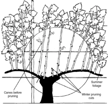
List of Figures: Figure 1: Reference and visual representation of a typical wine grape vine discussed in this project. The type of pruning done in this project is called bilateral cordon spur pruning, where the canes are trimmed back to a certain number of buds (also called positions or nodes) during the winter to ensure that each grape cluster gets the same amount of resources from the grapevine [1]. Image source: Grainger and Tattersall [1]. ... 5
Figure 2: Level Zero Block Diagram ... 11
Figure 3: Level One Block Diagram ... 12
Figure 4a: Gantt Chart tasks, descriptions, and durations ... 15
Figure 4b: Gantt Chart for the completion of this project during the 2019-2020 school year ... 16
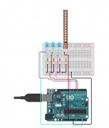
Figure 5: Simple breadboard diagram of the final prototype. This figure does not show the Arduino Ethernet Shield with SD card, but all the pins remain the same. ... 18
Figure 6: Schematic of the entire system, minus the Ethernet breakout board, which follows the same pinout as the Arduino Uno. ... 21
Listing 1: The Arduino sketch employed in this project to measure the resistance of the FSR, compare it to calibrated values, display whether to leave one, two, or three positions, and to record the times and size of the cut to the SD card. ... 25
Listing 2: “FSR testing sketch” by Adafruit. Retrieved from [10]. ... 27
Figure 7: Serial output when the flex resistor mounted on the shears is bent and then unbent. This shows that there is enough variations between the AnalogRead values to be able to determine the difference between small, medium, and large canes. ... 27
Figure 8: Example output CSV as read in Excel after making six “fake” cuts on the specimen used as training data for this project. The index number of the cuts made that day, time elapsed since turn on of the system, and size of the cut are shown in the CSV when read from the SD card. ... 29
Figure 9: Quick reference for vineyard-related vocab used in this manual. The canes are the extra growth on the spurs, which will be trimmed off during the process of pruning. Source: Grainger and Tattersall [1]. ... 32
Figure 10: Demonstration of the front of the shears and the arrow marking ... 33
Figure 11: Example short flex sensor used in this project. It is imperative that the flex has a high resistance variance, in order to get enough difference in analog read values to measure different spur widths to the tenth of a millimeter. ... 34
Figure 12: Schematic for the use of the Flexible Resistor as a sensor. ... 35
Figure 13: Demonstration of the position of the flex sensor to be used in this project ... 35
3
Acknowledgements
This project was made possible by many. Firstly, I’d like to thank Drs. Jean Dodson Peterson and Andrew Danowitz, for their steadfast advising no matter the state of the world. When the first design of the project, an optical encoder, did not give the resolution needed for this project, it was Dr. Danowitz who suggested a force-sensitive resistor. Dr. Dodson Peterson’s patience in teaching me everything I needed to know about viticulture for this project is something I will forever be grateful for. This project was also made possible by the Baker-Koob grant, which allowed for more designs to be considered due to their generous funding of this project.
4
Abstract
This report documents the design of a field-safe and portable tool that helps field hands identify how many wine grape nodes to prune per cane. This practice allows for a more bountiful harvest [1]. The device indicates to the worker whether to leave one, two, or three nodes on a cane. The device is attachable to a set of industry-standard shears to allow for efficient and cost-effective pruning.
5
Chapter 1: Introduction
The objective of this project is to develop a tool that significantly reduces the amount of training time needed for vineyard pruning field workers and to standardize the vineyard pruning practice.
This project blends electrical engineering principles, viticulture, and mechanical engineering knowledge to implement the measurement electronics into a pair of shears in a safe and portable way. The impact of this project is reduced training times for both field hands and viticulture students as well as improved grape yields. There currently exists no similar training tool for vineyard pruning.
The aims of this project are twofold: one, to characterize the typical widths of each wine grape cane to determine whether to leave one, two, or three nodes on the cane [1]; and two, to
implement a device that will measure a cane’s diameter and display to the user how many nodes to leave based on the cane measurement. In Spring 2020, the additional request was made to log each cut made by this device so that research regarding the amount of small, medium, and large canes within certain parts of a vineyard can be conducted.
The first phase of this project was the characterization of the typical diameters of spurs with the assistance of Dr. Dodson Peterson, and the second phase of this project was fabricating a
prototype of a digital measurement setup and integrating it as an attachment for industry standard shears.
Figure 1: Reference and visual representation of a typical wine grape vine discussed in this project. The type of pruning done in this project is called bilateral cordon spur pruning, where the canes are trimmed back to a certain number of buds (also called positions or nodes) during the winter to ensure that each grape cluster gets the same amount of resources from the grapevine
6 In December 2019, Dr. Dodson Peterson and I went to the Cal Poly vineyards and used
traditional measurement methods (calipers, rulers) to measure and characterize average cane diameter that correlates with leaving one, two, or three nodes on the cane, respectively [2].
The electrical prototyping plan involved using a flexible force-sensitive resistor to accurately take cane measurements. Based on where the pruning blades stop, the flexible resistor will send the information of the blade’s current position to a microcontroller, which will signal to the display to show to the operator how many nodes to leave on the cane [3]. Once accurate measurement electronics were built, they were implemented in a prototype that fit over the shears. The remaining electronics not used for sensing are hard-wired to the shears and housed in a small bag, similar to other industry-standard electronic shears, such as the Felco 802 [4]. A display is mounted on the shears as well, which signals to the operator the number of nodes to leave on the cane, based on the output of the measurement sensor.
Finally, the electrical measurement design was tested using the sample canes obtained in
December 2019. Further field testing was planned for the spring of 2020, but due to the outbreak of COVID-19, was unable to be performed. A final prototype created from this project is
7
Chapter 2: Customer Needs Assessment
This product is primarily designed for use in a research setting or in training new field workers on proper vineyard pruning techniques.
Additionally, the tool could be modified to fit the needs of different plants in the future, to cater to home gardeners and farmers.
The customer needs for this project are for a tool that is:
1. Portable
2. Easy to use and understand 3. Rugged enough for field work 4. Accurate
8
Chapter 3: Requirements and Specifications
The focus of this project is portability and durability. If the tool cannot survive 8-hour workdays in the fields with thousands of pruning cuts each day, the tool is essentially useless [5].
Additionally, this tool needs to clearly and concisely tell the operator whether to leave one, two, or three nodes on the cane. This project must be an add-on to industry standard shears to allow for simple and cheap setup.
Table 1: Training tool for vineyard trimming requirements and specifications
Marketing
Requirements
Engineering
Specifications
Justification
1,3,5 Weigh 1 pound or less Industry standard vine pruning shears are all a little less than a pound in weight.
1 Battery life of over 8
hours
A typical American workday is 8 hours long. People using this tool should not have to go back to a power source multiple times a day and further interrupt their pruning schedule.
2 Waterproof to one meter It rains, there is always water around plants, and the trimmers could be dropped in a bucket for cleaning, for example.
2 Able to be used 100 times
a day for three months
This was the original estimation, but as shown in table 7, the shears should be expected to make over 2000 cuts in a day, according to Dr. Dodson Peterson.
3 Requires less than ten
minutes to train an employee in its operation
Educators and vineyard owners want an easy, quick way for their employees to know how many positions to leave on each cane. Employees should be able to understand how to use this tool in ten minutes or less.
4 Measure the width of the
cane caliper to 10% accuracy
As found in January 2020, a small cane caliper is anything under 7.5mm in diameter, medium is 7.5 to 10mm in diameter, and large is anything over 10mm in diameter [2].
5 All electronics must be
small enough to fit in/over industry standard shears
9
Marketing
Requirements
Engineering
Specifications
Justification
Marketing Requirements
1. Portability 2. High Durability 3. Ease of use
4. High measurement accuracy
10
Table 2: Training tool for vineyard trimming deliverables
Delivery Date Deliverable Description
10/28/19 Meet with Dr. Dodson Peterson and Dr. Danowitz
12/6/19 Cane caliper definitions established
1/10/20 Initial Design Review
2/28/20 EE 461 demo
3/6/20 EE 461 report
5/8/20 EE 462 demo
5/15/20 ABET Sr. Project Analysis
5/28/20 Sr. Project Expo Demo Video
11
Chapter 4: Functional Decomposition (Level 0 and Level 1
Block Diagram)
Figure 2: Level Zero Block Diagram
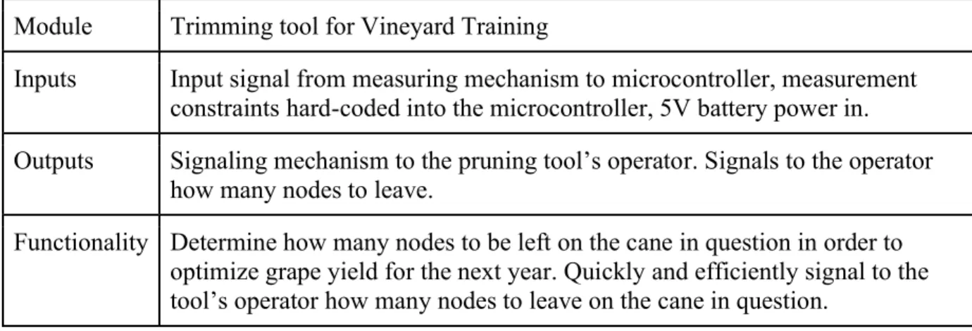
Figure 2 and table 3 show the lowest level of detail for this project. The electrical design for this project consists of some sort of battery-powered electrical device to measure the cane caliper and output the number of nodes to be left on the trimmed cane. Table 3 clarifies each of the blocks shown in figure 2 and justifies why each block was selected for the level zero block diagram.
Table 3: Level Zero Block Diagram
Module Trimming tool for Vineyard Training
Inputs Input signal from measuring mechanism to microcontroller, measurement constraints hard-coded into the microcontroller, 5V battery power in.
Outputs Signaling mechanism to the pruning tool’s operator. Signals to the operator how many nodes to leave.
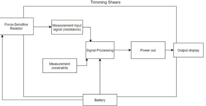
12 Figure 3: Level One Block Diagram
Figure 3 and table 4 show expanded versions of figure 2 and table 3, respectively. The purpose of a level one block diagram is to detail the mechanics of how the goals set in the level zero block diagram (figure 2) are achieved. Figure 3 shows the main mechanics of this project: a force-sensitive resistor is read by the microcontroller to convert linear displacement of the pruning shears into an analog reading. From pre-programmed constraints loaded onto the
microcontroller, the analog reading is compared to the constants, and the display shows whether to leave one, two, or three positions on the cane.
Table 4: Level One Block Diagram
Module Trimming tool for Vineyard Training
Inputs Input signal from measuring mechanism (force-sensitive resistor) to microcontroller, 5V battery power in.
Outputs Signaling mechanism to the pruning tool’s operator. Signals to the operator how many positions to prune to.
13
Chapter 5: Project Planning
Table 5: Cost Estimates
Item Estimated Cost + Labor Justification Industry standard pruning shears
$60 The midpoint for standard shears is about $50, plus shipping costs.
Small microprocessor $25 A small microprocessor, such as the Arduino Uno, was selected for this project.
Assorted electronic prototyping equipment (sensors, proto-boards, jumper wires,
batteries, chargers)
$100 The force-sensitive resistor is about $10, the batteries are about $30 each, chargers are $5 each. I will need a kit of resistors and capacitors to prototype, and I will also need wires and solder to make connections. I would like to be able to have extra parts so that if one breaks, I will have a replacement ready.
Assorted mechanical prototyping equipment (3D filament, metal, shear sheath)
$50 I need to have the electronic equipment fit seamlessly into the shears, so I will need to have some sort of mechanical housing to allow for a comparable grip to be used
My time $35/hr. actual cost $0/hr.
I get paid nothing for this, and it is estimated I will work for 10 hours a week on this project for 22 weeks. I was paid $35 an hour at my previous internship. Therefore, $7,700 of my time is not included in this budget.
Total: $235
14 A design that was fully prototyped but ultimately scrapped due to calibration reliability used an optical encoder to delineate the distance traveled by the shear blades as they were being
squeezed around a cane. Due to issues of the sensor reading differently in different light
conditions and the inability of the shears to be housed in a completely light-proof environment, the optical encoder design was scrapped. After switching to the force-sensitive resistor, multiple iterations of placement and orientation on the shears were developed, requiring three purchases of two different types of force-sensitive resistors so that each of the designs could be compared.
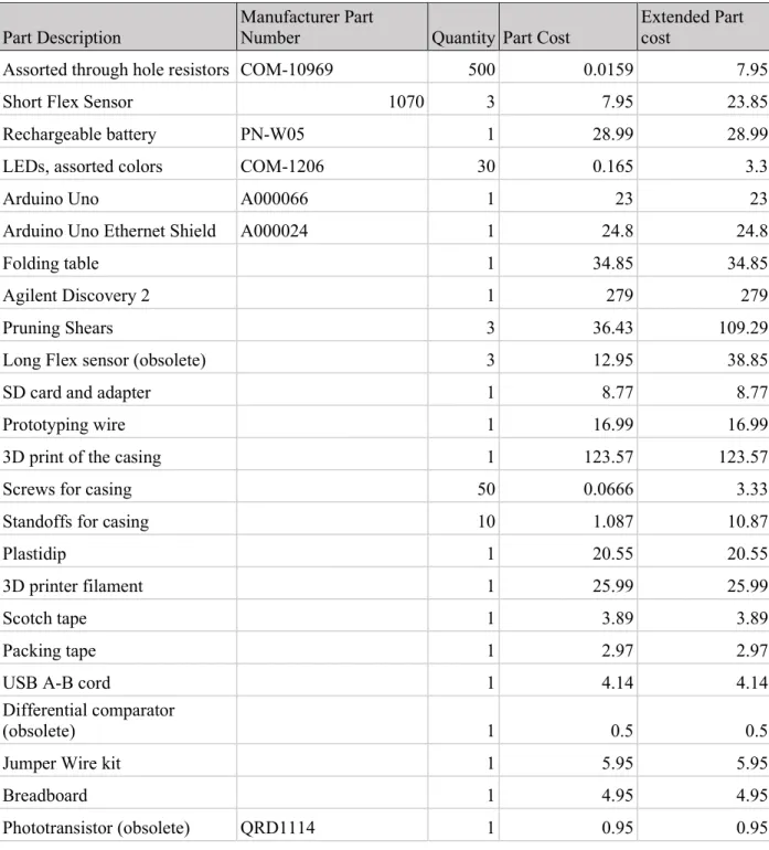
Table 6: Actual Project Costs
Part Description
Manufacturer Part
Number Quantity Part Cost
Extended Part cost
Assorted through hole resistors COM-10969 500 0.0159 7.95
Short Flex Sensor 1070 3 7.95 23.85
Rechargeable battery PN-W05 1 28.99 28.99
LEDs, assorted colors COM-1206 30 0.165 3.3
Arduino Uno A000066 1 23 23
Arduino Uno Ethernet Shield A000024 1 24.8 24.8
Folding table 1 34.85 34.85
Agilent Discovery 2 1 279 279
Pruning Shears 3 36.43 109.29
Long Flex sensor (obsolete) 3 12.95 38.85
SD card and adapter 1 8.77 8.77
Prototyping wire 1 16.99 16.99
3D print of the casing 1 123.57 123.57
Screws for casing 50 0.0666 3.33
Standoffs for casing 10 1.087 10.87
Plastidip 1 20.55 20.55
3D printer filament 1 25.99 25.99
Scotch tape 1 3.89 3.89
Packing tape 1 2.97 2.97
USB A-B cord 1 4.14 4.14
Differential comparator
(obsolete) 1 0.5 0.5
Jumper Wire kit 1 5.95 5.95
Breadboard 1 4.95 4.95
15 Part Description
Manufacturer Part
Number Quantity Part Cost
Extended Part cost
Line follower sensor (obsolete) 1 2.95 2.95
Motor encoder (obsolete) 2 2.865 5.73
Adafruit Metro Mini
(Obsolete) 1 18.18 18.18
Light sensor (obsolete) 1 7.5 7.5
Solder Paste (obsolete) 1 6.95 6.95
Solder 1 11.95 11.95
Proximity sensor (obsolete) 1 5.95 5.95
Total Project
Cost 866.51
Table 6 details all related costs to this project. All items marked “obsolete” denote items that pertain to designs that were scrapped.
17 Figures 4a and 4b detail the Gantt chart used in this project. The main deliverables for this
project were the final project prototype and the final project report. To achieve these
18
Chapter 6: Design Implementation and Considerations
Introduction to Design Plan
This project went through many versions and revisions. The original design plans used optical sensors and an encoder system for measuring the linear distance traveled by the blades of the shears. However, due to the large amount of variance in light in an outdoor setting, this design failed to have consistent calibration, thus, this idea was scrapped in favor of a system using a variable resistor as a potentiometer. The final design of this project uses an Arduino to take the analog reading of the resistor, and then compares that analog reading against calibrated values for small, medium, and large canes.
19
Table 7: Engineering specifications alterations/additions
2 Waterproof to 1 meter It rains, there is always water around plants, the trimmers could be dropped in a bucket for cleaning. -> Pruning shears do not have to be cleaned very often and can be wiped down with a wet cloth when needed.
2
Able to be used 100 2,000 times a day for 3 one month
This is an estimated number, it needs to be verified with Dr. Dodson Peterson, but it was estimated that a person out in the fields needs to trim at least 100 vines each day for a 3 month period (winter). Wine grapes need to be pruned in a few days of intense work to prune a vineyard. Dr. Dodson Peterson also made a rough estimate that there should be room for 2,000 datapoints of cuts per day in the shears.
2 Allow for approximately 2,000 cuts per day to be logged by size of cut (small, medium, or large) and exported in a file for research
This was achieved by adding on the Arduino Ethernet shield, which allows for an SD card to be read from and written to. The code of this project accommodates for this and allows for all data from the day to be saved and logged if the SD card from the shears is plugged into a computer at the end of a day.
Marketing Requirements
1. Portability 2. High Durability 3. Ease of use
4. High measurement accuracy
5. Be a modification of industry standard shears
Table 8: Components list
Component Quantity Purpose
Pruning Shears 1 The base of this project. Industry standard wine
grape pruning shears
Force-Sensitive Resistor 1 Small force-sensitive resistor that increases resistance as it is bent
LEDs 3 Acts as the display for the project. One light for
small canes (leave one bud), two lights for medium canes (leave two buds), and three lights for large canes (leave three buds).
Assorted Resistors 4 Pull down resistors and current sinks
Arduino Uno 1 Microcontroller for the project.
20 Part Selection
The microcontroller used in this project is an Arduino Uno. It was selected for its low price, reliability, and wealth of pre-existing libraries, documentation, and code. It has 14 digital input/output pins, six of which can be used as PWM outputs [6]. Additionally, it has six analog inputs, a USB connection, a power jack, an ICSP header and a reset button. It operates at 5V and supports input voltage from 6V-20V. It works with a 16MHZ clock, has 31.5KB Flash Memory, 2KB SRAM, and 1KB EEPROM [6]. Additionally, the Arduino Uno allowed for a pre-existing design, the ethernet shield, to be used in order to increase the data storage and ease of use of this project [6].
Further work could repeat this project but with a more cost-effective development board such that the support for the SD card was not needed as an additional purchase. For this design, the Arduino and the Arduino Ethernet shield are required, and the purchase of both is $47.80. Equipping a team or a class with this project is certainly more cost effective than the $2,280 Felco 802 shears available from Felco [4] but could certainly be improved. The Felco 802 shears are the industry standard electronic pruning shears and are the closest commercial product available that performs similar functions to this project. At the end of the day, the Felco 802 can report back how many small, medium, and large cuts were made during the day, but don’t have anything to show an operator whether to leave one, two, or three positions on the cane in real time [4].
The variable resistor selected is the three-inch short flex sensor from Adafruit, ID 1070 [3]. It was selected for its high range of available resistances (25KΩ completely unflexed to 100KΩ completely flexed), to allow for measurements to be taken to the nearest tenth of a millimeter in this project [3].
The hard storage device was chosen to be a SanDisk 32 GB micro SD card. This is well over the necessary amount in order to save a day’s worth of data, since the Arduino stores the cuts as ints and then uses those to increment a tally on a CSV, as well as storing the index, size, and
timestamp of the cut. For reference, the battery test performed in Section 7 of this report logged 533 cuts over 44 hours, and the final file size was 16 KB. However, the SD card is useful in this design since it provides a familiar user interface as well as prevents difficulties in transferring data from the Arduino to the computer.
21 127mA and the battery charges at 230mA, conditions such as temperature, shade, and angle of the sun in relation to the battery make it so this system cannot rely entirely on solar power [8].
Schematic
Figure 6: Schematic of the entire system, minus the Ethernet breakout board, which follows the same pinout as the Arduino Uno.
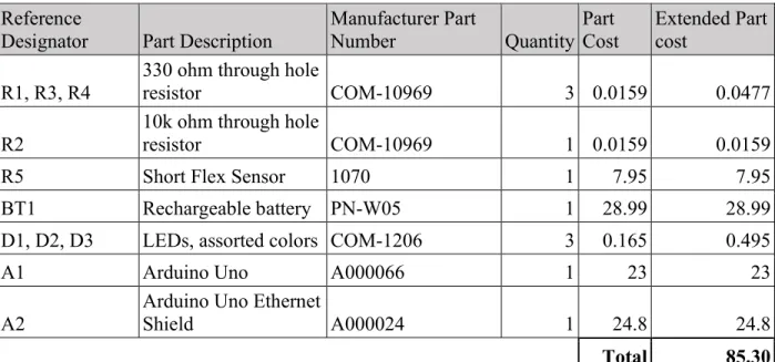
Table 9: Bill of Materials
Reference
Designator Part Description Manufacturer Part Number Quantity Part Cost Extended Part cost
R1, R3, R4
330 ohm through hole
resistor COM-10969 3 0.0159 0.0477
R2
10k ohm through hole
resistor COM-10969 1 0.0159 0.0159
R5 Short Flex Sensor 1070 1 7.95 7.95
BT1 Rechargeable battery PN-W05 1 28.99 28.99
D1, D2, D3 LEDs, assorted colors COM-1206 3 0.165 0.495
A1 Arduino Uno A000066 1 23 23
A2
Arduino Uno Ethernet
Shield A000024 1 24.8 24.8
22 Theory of operation
The flexible resistor works by increasing its electrical resistance as it is bent. The resistance is then read by the AnalogRead function on the Arduino, and is in theory translated to a value between 0 and 255, with 255 indicating the resistor is completely relaxed and 0 indicating the resistor being completely bent [3]. In practice, the flex resistor had an analogRead of 244 when completely relaxed and 100 when completely bent.
The software was written with the assistance of a Cal Poly alumna, Sharon Kuang. The software employed in this project is written as a series of if/else statements that after initializing the SD card, finds if the analog reading of the variable resistor has settled on a resistance value,
indicating that the shears are around something to be measured. If the analog reading is settled, the software records the settled analog reading and matches it to known analog readings of small/medium/large cane width. It then records to the SD card the size of the cane that was last settled on after the user squeezes the shears completely shut and re-opens them after a cut. At the same time, the index of the cut as well as the time since the Arduino was powered on are
recorded. Finally, the code allows for a tally to be kept at the top of the CSV file that simply states the number of small, medium, and large cuts made that day. When the user resets the Arduino by pressing the “reset” button, the CSV file remains, but the variables for the tally of small, medium and large cuts are set back to zero.
The software employs the millis() function from the Arduino library to scale the Arduino’s clock to time events in seconds and minutes instead of milliseconds [9]. The time since startup of the system is recorded when a cut is made, and printed next to the current cut number and size of the cane in the CSV file for each cut made.
When the program starts up, it initializes the SD card and checks to see if there exists a file named cuts.csv on the SD card. If there is no such file, the program will then create a file called cuts.csv and write that there are zero small, medium, and large cuts. Since the maximum amount of cuts expected is 2,000 a day, the character buffer is 36 long, in order to account for the size of the formatted string written to the csv. This format includes the strings “small”, “medium”, and “large”, newlines, commas, and the final null character. A similar character buffer is used to print a formatted string holding the time, size and index of cut.
23 Code
/* Sr Project Spring 2020 -- Cal Poly * Vineyard training tool
* Cate Thornbury and Sharon Kuang
************* Calibration Instructions **************** * Run Program on Arduino IDE, open Serial Monitor
* Change "LowerEnd", to the analogRead of a 7.5 mm object * Change "UpperEnd" to the analogRead of a 10 mm object
* Change "Open" to the Analog read when shears are completely open
* Change "Closed" to a couple values above the analogRead of the shears closed */
#include <SPI.h> #include <SD.h>
#define NOTSET -1
#define SMALL 0
#define MEDIUM 1
#define LARGE 2
#define SIZESET 5
#define fsrAnalogPin 0 // FSR is connected to analog 0
#define GREEN 3 // the pin the LED is connected to
#define YELLOW 2
#define RED 5
// ******** Calibration variables (change these) **************** int LowerEnd = 130;
int UpperEnd = 145; int Open = 180; int Closed = 100;
// ******* End calibration variables ************
int fsrReading; // the analog reading from the FSR resistor divider File logFile;
const char* fileName = "cuts.csv";
const char sizeFormat[][7] = {"Small","Medium","Large"}; const char* format = "#%d - %02d:%02d:%02d - %s\n";
const char* formatTotal = "Small,%d\nMedium,%d\nLarge,%d\n"; int lastSetSize = 0;
int countsAtSize = 0; int cutSize = 0; int cutNumber = 0; char chrBuffer[37];
void setup() {
pinMode(GREEN, OUTPUT); // Declare the LED as an output pinMode(YELLOW, OUTPUT);
pinMode(RED, OUTPUT);
Serial.begin(9600); // We'll send debugging informatTotalion via the Serial monitor
Serial.print("Initializing SD card..."); bool sdInit = SD.begin(4);
while (!sdInit) {
24
}
Serial.println("initialization done."); if (!SD.exists(fileName)){
logFile = SD.open(fileName, FILE_WRITE); if (logFile){
sprintf(chrBuffer,formatTotal,0,0,0); logFile.print(chrBuffer);
logFile.close(); } else {
Serial.print("could not create file"); }
} }
void loop(void) {
fsrReading = analogRead(fsrAnalogPin); Serial.println(fsrReading);
if (fsrReading < Closed){ //cut is made
if (lastSetSize != NOTSET){ logCut(lastSetSize); }
//reset cut size after logging lastSetSize = NOTSET;
cutSize = NOTSET; countsAtSize = 0;
} else if (fsrReading < LowerEnd){
if (cutSize == SMALL && countsAtSize < SIZESET){ countsAtSize++;
} else{
countsAtSize = 0; }
cutSize = SMALL;
digitalWrite(GREEN, HIGH); digitalWrite(YELLOW, LOW); digitalWrite(RED , LOW); delay(150);
} else if (fsrReading <= UpperEnd) {
if (cutSize == MEDIUM && countsAtSize < SIZESET){ countsAtSize++;
} else{
countsAtSize = 0; }
cutSize = MEDIUM;
digitalWrite(GREEN, HIGH); digitalWrite(YELLOW, HIGH); digitalWrite(RED , LOW); delay(150);
} else if (fsrReading < Open){
if (cutSize == LARGE && countsAtSize < SIZESET){ countsAtSize++;
} else{
countsAtSize = 0; }
cutSize = LARGE;
25
digitalWrite(RED , HIGH); delay(150);
} else {
//shears open
digitalWrite(GREEN, LOW); digitalWrite(YELLOW, LOW); digitalWrite(RED , LOW); }
if (countsAtSize == SIZESET){ lastSetSize = cutSize; }
}
void logCut(int cut){ int cuts[3];
char cutBuffer[22];
unsigned long currentTime = millis(); int seconds = (currentTime/1000)%60; int mins = (currentTime/60000)%60; int hours = currentTime/3600000; cutNumber++;
logFile = SD.open(fileName, FILE_READ); logFile.read(chrBuffer,36);
logFile.close();
sscanf(chrBuffer,formatTotal,&cuts[0],&cuts[1],&cuts[2]); cuts[cut]++;
sprintf(chrBuffer,formatTotal,cuts[0],cuts[1],cuts[2]);
sprintf(cutBuffer,format,cutNumber,hours,mins,seconds,&sizeFormat[cut]); Serial.println(chrBuffer);
Serial.println(cutBuffer);
logFile = SD.open(fileName, O_WRITE); if (logFile){
logFile.seek(logFile.size()); logFile.print(cutBuffer); logFile.seek(0);
logFile.print(chrBuffer); logFile.close();
} }
Listing 1: The Arduino sketch employed in this project to measure the resistance of the FSR, compare it to calibrated values, display whether to leave one, two, or three positions, and to
26
Chapter 7: Testing
Power Calculations
Using the Analog Discovery 2 and a multimeter, the 5V output of the Analog Discovery was connected in series with the multimeter. 5V was supplied to the system with a current meter in series with the power into the system. Using this setup, it was measured that the system drew 114mA in standby mode, and the system drew 127mA with the LEDs illuminated (shears squeezed shut). Since the system runs on 5V, the power consumed on standby is 0.57W, and with the LEDs illuminated it consumes 0.635W.
Testing the Flex Resistor
After soldering leads onto the flex resistor, a multimeter set to measure resistance was used to observe the variance in resistance as the flex resistor was bent and straightened. This ensures that the soldering of the leads did not cause a break in the connection of the flex resistor, nor are there shorts between the two leads of the resistor, which are close to each other. The leads need to have sufficient strain relief so that the soldered-on leads to the flex resistor do not snap when the flex resistor is bent.
The following code was used to obtain the analog readings of the shears being closed and then opened again [10]. Using the output of the AnalogRead on the serial monitor of the Arduino IDE, figure 7 was obtained.
/* FSR testing sketch.
Connect one end of FSR to 5V, the other end to Analog 0. Then connect one end of a 10K resistor from Analog 0 to ground Connect LED from pin 11 through a resistor to ground
For more information see www.ladyada.net/learn/sensors/fsr.html */
int fsrAnalogPin = 0; // FSR is connected to analog 0
int LEDpin = 11; // connect Red LED to pin 11 (PWM pin)
int fsrReading; // the analog reading from the FSR resistor divider int LEDbrightness;
void setup(void) {
Serial.begin(9600); // We'll send debugging information via the Serial monitor pinMode(LEDpin, OUTPUT);
}
void loop(void) {
fsrReading = analogRead(fsrAnalogPin); Serial.print("Analog reading = "); Serial.println(fsrReading);
// we'll need to change the range from the analog reading (0-1023) down to the range // used by analogWrite (0-255) with map!
LEDbrightness = map(fsrReading, 0, 1023, 0, 255); // LED gets brighter the harder you press
27
delay(100); }
Listing 2: “FSR testing sketch” by Adafruit. Retrieved from [10].
Figure 7: Serial output when the flex resistor mounted on the shears is bent and then unbent. This shows that there is enough variation between the AnalogRead values to be able to determine the
difference between small, medium, and large canes.
Calibrating the Flex Resistor
The flex resistor was calibrated in the following manner.
1. Run the Arduino IDE on a computer, and open a new file containing the code (Listing 1) provided in Chapter 6.
2. Connect the USB side of the Arduino power cable to a computer running the Arduino IDE.
3. Launch the serial monitor. It should be displaying the analog reading of the flex sensor on the shears.
4. Update the value of the variable “Open” in the variables section of the code to reflect the analog reading of the shears in the open position.
5. Using the calibration 3-D print or an equivalent object that is 7.5mm in diameter, place the 7.5mm diameter object in the measurement area of the shears.
28 a. Repeat this step and take the average of several measurements for better accuracy. 7. Update the value of the variable “LowerEnd” in the variables section of the code to
reflect the analog reading of the 7.5mm object measured and recorded.
8. Using the calibration 3-D print or an equivalent object that is 10mm in diameter, place the 10mm diameter object in the measurement area of the shears.
9. Record the Analog reading from the serial monitor when the shears are around the object that is 10mm in diameter.
a. Repeat this step and take the average of several measurements for better accuracy. 10.Update the value of the variable “UpperEnd” in the variables section of the code to
reflect the analog reading of the 10mm object measured and recorded.
11.Update the value of the variable “Closed” in the variables section of the code to reflect the analog reading of the shears completely closed.
12.Upload the code with the new calibrated values to the board.
Writing to the SD Card
When the program starts up, it initializes the SD card and checks to see if a file named cuts.csv exists on the SD card. In order to test that the Arduino is communicating with the SD card as expected, insert a microSD card into the SD card slot on the Arduino, power the system on, and press the reset button. Remove power to the system, then remove the SD card and insert it into a computer for reading. If there exists a file called “cuts.csv” with three rows stating small, medium, and large, the Arduino is functioning properly.
Testing the Battery
To verify calculations done in Section 6 of this report showing that the battery life of this system is expected to last 87.72 hours in optimal conditions, the Arduino was programmed to run all the program code as usual but write to a CSV a dummy cut every 5 minutes to show that the battery was alive and everything was working as normal. In order to simulate a worst-case scenario, the system was left in the dark so it could not charge the battery using the solar panel. The ending CSV showed that the Arduino lost power after 44 hours and 25 minutes and 533 dummy cuts, meaning that it has a battery life of a little under 44.5 hours of mixed use.
There are a multitude of reasons why the battery life of this project in practice is significantly lower than the calculated battery life, some being that the battery was never tested in its actual full capacity, since the student did not have equipment to measure that. Additionally, the
29 Testing the Whole System
Example canes collected by Dr. Dodson Peterson during the 2019 pruning season were used to simulate canes that would be cut during a typical pruning season. The bottom of each of the canes was measured first with digital calipers to ensure that the diameter measurements were in agreement with the 7.5 mm and 10mm guidelines put in place by vineyard experts [1].
The whole system was then tested by making numerous “fake” cuts (pulling the cane out of the shears before closing the shears) and ensuring that the data was written to the SD card as
expected. In Figure 8 below, two small, two medium, and two large canes were selected to make “fake” cuts. The output of the software when making these “fake” cuts is as shown below in figure 8.
Figure 8: Example output CSV as read in Excel after making six “fake” cuts on the specimen used as training data for this project. The index number of the cuts made that day, time elapsed
30
Chapter 8: Conclusion and Future Work
Future work could include the modification of this prototype into something that can be better mass-produced, as well as modifications and a new prototype as needed from direct field testing. Finally, increasing the manufacturability of this project would involve a custom PCB to be designed to substitute for an off-the-shelf development board.
Additionally, the original scope of this project had the project being tested in the vineyards during the 2020 pruning season, but due to COVID-19, it is necessary for this project to have its first full field test during the winter of 2021, assuming that the pandemic has abated by that time. Testing of this project was limited because it was not possible to get this project into the fields during the winter of 2020. Testing was done by calculating an estimated power usage per day and then extrapolating that to the battery capacity. Additionally, the unit was left on and in standby mode to see how long it would last, which ended up being 44 hours and 25 minutes.
31
References:
[1] K. Grainger and H. Tattersall, “Chapter 4: The Vineyard.” Wine Production and Quality, John Wiley & Sons, 2016, pp. 36–50, [E-book] Available:
ebookcentral.proquest.com/lib/calpoly/reader.action?docID=4306430#.
[2] Pokorny, Kym. “Don't Be Timid When Pruning Grapes.” OSU Extension Service, Oregon State University , 29 May 2019. [Online] Available:
extension.oregonstate.edu/news/dont-be-timid-when-pruning-grapes.
[3] Adafruit. “Short Flex Sensor.” Adafruit.com, 2020. [Online] Available: adafruit.com/product/1070
[4] FELCO. “FELCO 802.” Electric Pruning Tools, Felco.com, 2020. [Online] Available: felco.com/us_en/our-products/powertools/felcotronic-electric-tools/felco-802.html
[5] P. Skinkis, V. Walton, A.J. Dreves, C. Kaiser, S. Renquist, S. Castagnoli, R. Hilton, L. Brewer. “Recognize the Symptoms and Causes of Stunted Growth in Vineyards.” Oregon State University Journal of Agriculture, ser. EM8975, Jan. 2019. [Online] Available: catalog.extension.oregonstate.edu/em8975.
[6] Arduino. “Arduino Uno,” 2020. [Online] Available: store.arduino.cc/usa/arduino-uno-rev3
[7] BLAVOR. “10,000mAh Solar Power Bank.” Amazon.com, 2020. [Online] Available: amazon.com/Solar-Power-Charger-Flashlight-Splashproof/dp/B07FDXDB3W
[8] K. Wedel. “How to Charge Your Phone Using Only Solar Power.”
AndroidCentral.com, April 22, 2020. [Online] Available: androidcentral.com/how-charge-your-phone-using-only-solar-power
[9] Arduino. “millis()” 2020. [Online] Available: arduino.cc/reference/en/language/functions/time/millis/
[10] L. Fried. “Force Sensitive Resistor (FSR)” Adafruit, July 29, 2012. [Online] Available: learn.adafruit.com/force-sensitive-resistor-fsr
32
Appendix A: User Manual
User Instructions
This product is primarily designed for use in a research setting or in training new field workers on proper vineyard pruning techniques. Vineyard pruning generally requires someone to have knowledge to intuitively tell whether to leave one, two, or three spur positions for new shoot development in the coming year. The delineation between one, two, or three positions as used in this project is that one position shall be left on any spur below 7.5 mm in diameter, two positions on 7.6-10mm diameter spurs, and three positions left on any spur above 10mm in diameter [1].
Figure 9: Quick reference for vineyard-related vocab used in this manual. The canes are the extra growth on the spurs, which will be trimmed off during the process of pruning. Source: Grainger
and Tattersall [1].
Typical use operation
Start of the day:
Ensure that the battery is charged and connected (The USB port from the battery to the USB slot on the Arduino housing).
33 Press the reset button on the Arduino housing to initialize the Arduino for collecting
data for the day.
Replace the Arduino Housing to ensure no accidental resets if the electronics bag is jostled.
When at a cane that needs spur pruning:
Line up the spur with the arrow marked on the shears, as shown in figure 10 below.
Figure 10: Demonstration of the front of the shears and the arrow marking
Gently squeeze the shears and observe the LEDs on the handle of the shears.
o One illuminated LED = leave one position (small-sized cane).
o Two illuminated LEDs = leave two positions (medium-sized cane).
o Three illuminated LEDs = leave three positions (large-sized cane).
Either squeeze the shears completely after an LED has illuminated and settled on a measurement, or completely release and squeeze the shears to cut as with standard shears. Either is fine, the cut size will be recorded in the SD card either way. As long as the shears are not held in one position (that is not completely released)
continuously for more than a second, no extra cuts will be accidentally recorded. Release shears fully to complete data recording.
At the end of the day (or whenever data is desired to be extracted from the SD card):
Remove the Arduino housing from the electronics housing bag.
34 Remove the micro SD card from the Arduino (Note: it is now safe to disconnect the
battery).
Insert the micro SD card to an SD card adapter and then insert the SD card into a computer
Copy data from the SD card (there should be a file called “cuts.csv”).
Copy “cuts.csv” and rename with date of pruning, and other information needed for cataloging the cuts for the day.
Delete “cuts.csv” on the SD card from the file explorer on the computer.
Remove the SD card from the computer, take the micro SD card from the SD card adapter, and replace the micro SD card in the SD card slot on the Arduino Ethernet Shield.
Repair/troubleshooting manual
Replacing the flex sensor:
Obtain a new flex sensor from https://www.adafruit.com/product/1070 or equivalent. Solder long leads (long enough to reach from the electronics housing bag to the shears – I
used leads about a meter long) to each of the pins, as marked by red arrows in figure 11 below.
Figure 11: Example short flex sensor used in this project. It is imperative that the flex has a high resistance variance, in order to get enough difference in analog read values to measure different
spur widths to the tenth of a millimeter.
35 On the end of the wires that are to go into the Arduino, either attach stiff solid-core wire
to go into the female headers on the Arduino board or attach a male jumper wire header to allow for a connection to the Arduino board.
Solder a 10k Ω resistor to one of the long wires, on the end that’s closest to the Arduino. I found that it is easiest to cut off about one mm of the header and then solder the 10K Ω
resistor directly onto the exposed header pin.
Connect to the Arduino as shown in figure 12 below.
Figure 12: Schematic for the use of the Flexible Resistor as a sensor.
Mount (using tape or glue) the flex on the shears as shown such that when the shears are squeezed to make a cut, the striped side of the flex bends upwards (towards the operator), as shown in figure 13 below.
36 Follow the calibration instructions as shown below.
Calibrating the measurements of the shears
1. Run the Arduino IDE on a computer, and open a new file containing the code provided in
Chapter 6.
2. Connect the USB side of the Arduino power cable to a computer running the Arduino IDE.
3. Launch the serial monitor. It should be displaying the analog reading of the flex sensor on the shears.
4. Update the value of the variable “Open” in the variables section of the code to reflect the analog reading of the shears in the open position.
5. Using the calibration 3-D print or an equivalent object that is 7.5mm in diameter, place the 7.5mm diameter object in the measurement area of the shears.
6. Record the Analog reading from the serial monitor when the shears are around the object that is 7.5mm in diameter.
a. Repeat this step and take the average of several measurements for better accuracy. 7. Update the value of the variable “LowerEnd” in the variables section of the code to
reflect the analog reading of the 7.5mm object measured and recorded.
8. Using the calibration 3-D print or an equivalent object that is 10mm in diameter, place the 10mm diameter object in the measurement area of the shears.
9. Record the Analog reading from the serial monitor when the shears are around the object that is 10mm in diameter.
a. Repeat this step and take the average of several measurements for better accuracy. 10.Update the value of the variable “UpperEnd” in the variables section of the code to
reflect the analog reading of the 10mm object measured and recorded.
11.Update the value of the variable “Closed” in the variables section of the code to reflect the analog reading of the shears completely closed.
38
APPENDIX B — ANALYSIS OF SENIOR PROJECT
DESIGN
Project Title: Training Tool for Vineyard Trimming
Student’s Name: Cate Thornbury Student’s Signature: Cate Thornbury
Advisor’s Name: Andrew Danowitz
Advisor’s Initials: ARD
Date: 6/12/20
• 1. Summary of Functional Requirements
A field-safe and portable tool must be created in order to help field hands identify how many wine grape nodes to prune to per cane in order to allow for a more bountiful harvest [1]. Due to typical pruning practices, the device needs to indicate to the worker whether to leave one, two, or three nodes on a cane. The device designed will be attachable to a set of industry-standard shears to allow for efficient and cost-effective pruning.
This project shall produce an add-on to industry standard pruning shears that allows people of any training or experience level to know how many grape nodes to leave on each cane when pruning wine grape plants in the winter. The training tool add-on shall be able to withstand a typical eight-hour workday and shall be able to be used in bright sun, clouds, and rain.
Additionally, the device designed should be able to differentiate between small, medium, and large canes, which require one node, two nodes, and three nodes to be left on the cane,
respectively. This will necessitate the characterization of cane calipers that necessitate pruning to one, two, or three nodes per cane, since the current pruning practice is based on the width of the worker’s fingers.
• 2. Primary Constraints
• Describe significant challenges or difficulties associated with your project or implementation. For example, what were limiting factors, or other issues that impacted your approach?
This assignment poses the challenge that a field-safe tool shall be made. This means that the tool will need to be rugged enough to be used to thousands of times a day, for eight hours a day, for about a week at a time. Additionally, there needs to be an implementation that allows for the user to use this tool for thousands of times a day and not have serious damage to their hands (extra from what standard shears would do).
39 Difficulties incurred in this project mainly revolved around not having the ability to have field testing and feedback. Unfortunately, the window for field testing for this project is pretty narrow each year, making it hard, if not impossible, to test multiple iterations of this project in one year.
• 3. Economic
• What economic impacts result?
Financial Capital-- the money and credit that produces goods. -- The Financial Capital will be concentrated mostly at the beginning of this project, since Financial Capital is needed to
prototype this project. Additionally, Financial Capital is required to get this prototype into the hands of workers for field testing, which requires a pretty long trip to the vineyards. Finally, money and credit is needed to acquire the electronics and mechanical prototyping goods for use in this prototype. This will be secured via grant funding, or will be self-funded with the help of the electrical engineering department.
Human Capital – Human Capital is defined as the skill, knowledge, and experience possessed by an individual viewed in terms of their value or cost to an organization. -- This project will allow for less trained workers to work as, or more, efficiently than highly trained workers. With increases in efficiency comes a decrease in total employment in some work sectors. However, in the agricultural sector, workers are paid based on how much labor they have done. Since this tool’s goal is to reduce time in pruning, the workers will be more productive and therefore be paid more. With more efficient pruning practices, the wine grape yield is expected to increase, meaning that the amount of grapes produced by the vineyard will be increased with the same number of vines and the same amount of natural resources per cane.
Manufactured or Real Capital – the assets used to produce a good. -- In order to produce this prototype, funding is required, as detailed in the Financial Capital section. In addition, testing equipment such as oscilloscopes and function generators will be required to test the electrical characteristics of this project.
Natural Capital – the resources consumed to produce a good. -- This project uses currently existing technology (pruning shears) and augments their use using electronics. This will require more resources than just the pruning shears, and electronics require rare materials and high carbon emissions for their manufacture.
• When and where do costs and benefits accrue throughout the project’s lifecycle?
The cost will most likely mostly accrue at the beginning of this project, with prototyping and development costs. Getting this tool manufactured after just rough prototypes could prove difficult and expensive. However, this tool’s goal is to build the worker’s intuition, so once the worker is thoroughly trained, they don’t need the training tool anymore. This means that one tool can train many workers for many years.
• What inputs does the project require? How much does the project cost? Who pays?
40 $2500, paid for by a grant by the school (Baker Koob)
Actual final cost of component parts (at the end of your project): $866.51
Attach a final bill of materials for all components.
Part Description Manufacturer Part Number Quantity Part Cost Extended Part cost
Assorted through hole resistors COM-10969 500 0.0159 7.95
Short Flex Sensor 1070 3 7.95 23.85
Rechargeable battery PN-W05 1 28.99 28.99
LEDs, assorted colors COM-1206 30 0.165 3.3
Arduino Uno A000066 1 23 23
Arduino Uno Ethernet Shield A000024 1 24.8 24.8
Folding table 1 34.85 34.85
Agilent Discovery 2 1 279 279
Pruning Shears 3 36.43 109.29
Long Flex sensor (obsolete) 3 12.95 38.85
SD card and adapter 1 8.77 8.77
Prototyping wire 1 16.99 16.99
3D print casing 1 123.57 123.57
Screws for casing 50 0.0666 3.33
Standoffs for casing 10 1.087 10.87
Plastidip 1 20.55 20.55
3D printer filament 1 25.99 25.99
Scotch tape 1 3.89 3.89
Packing tape 1 2.97 2.97
USB A-B cord 1 4.14 4.14
Differential comparator (obsolete) 1 0.5 0.5
Jumper Wire kit 1 5.95 5.95
Breadboard 1 4.95 4.95
Phototransistor (obsolete) QRD1114 1 0.95 0.95
Line follower sensor (obsolete) 1 2.95 2.95
Motor encoder (obsolete) 2 2.865 5.73
Adafruit Metro Mini (Obsolete) 1 18.18 18.18
41 Part Description Manufacturer Part Number Quantity Part Cost Extended Part cost
Solder Paste (obsolete) 1 6.95 6.95
Solder 1 11.95 11.95
Proximity sensor (obsolete) 1 5.95 5.95
Total Project Cost 866.51
• Additional equipment costs (any equipment needed for development?)
Due to the Covid-19 pandemic, an Analog Discovery 2 and a folding table had to be purchased to get scope captures, since campus and all campus laboratories were closed.
• How much does the project earn? Who profits?
Nothing unless I patent this design and put it into mass production for educational purposes.
• Timing: When do products emerge? How long do products exist? What maintenance or operation costs exist?
Prototypes started January 2020. They need to be further refined through field testing, which will be the next winter that the pandemic has abated. The products, should they be successful, could be patented and moved to mass production, where they can be sold to educators.
43 • What happens after the project ends?
I get it copyrighted by the Cal Poly IP department, or if it’s less successful, I call it a day and a learning experience and move on with my life.
• 4. If manufactured on a commercial basis:
• Estimated number of devices sold per year
100
• Estimated manufacturing cost for each device
$10
• Estimated purchase price for each device
$25
• Estimated profit per year
$1,500
• Estimated cost for user to operate device, per unit time (specify time interval)
If it costs $25 to train one person for three days, their entire training = $8.34/day. This can be then further divided by how many employees are trained by the same device over the years.
• 5. Environmental
44 Whenever electronics are manufactured, they require rare materials and high carbon emissions for their manufacture. This will require more resources than just the pruning shears. I’m estimating that per unit, there should be about five pounds of carbon emissions produced from manufacturing the electronics. Luckily, Arduino, which I’m using to prototype, is a carbon-neutral company, so I don’t have to include their emissions into my estimations. The rest is from the lithium-ion battery, the encoder, and the housing. The final emissions really depend on how and when and if this product is manufactured.
• Which natural resources and ecosystem services does the project use directly and indirectly?
This project requires energy to operate. Therefore, it needs coal, wind, nuclear, solar, or other power sources to function and charge the battery. The battery needs lithium-ion, which is becoming rarer with their popularity for batteries.
• Which natural resources and ecosystem services does the project improve or harm?
This project harms the ecosystem to a degree depending on where the energy is sourced from. It has the lowest emissions if the battery is charged from renewable resources, but that also requires the emissions from making the harvesters of renewable resources. This project could improve the environment if it’s manufactured, and a portion of profits is set for planting trees or conservation.
• How does the project impact other species?
This project impacts the wine grape vines, which can signal distress when they are cut or otherwise damaged. The wine grape vines will possibly have more cuts than before, since this project trains employees in efficiently pruning wine grape vines. Additionally, there comes the regular impacts of deforestation for mining for the materials needed for manufacturing
electronics similar to those used in this project.
• 6. Manufacturability
• Describe any issues or challenges associated with manufacturing.
Due to the nature of this project, the product of this project will be a prototype of something to be manufactured. After all the field testing conducted this year, it will not be the exact same product that could be manufactured at the end of this project. Therefore, a first run of
professionally manufactured versions of this project (should they exist) will need to be tested in the field during pruning season 2021 before further dissemination.
• 7. Sustainability
• Describe any issues or challenges associated with maintaining the completed device, or system.
45 • Describe how the project impacts the sustainable use of resources.
This project aims to have each device used for multiple people for multiple years. Hopefully, this will cut down on the amount of electronic waste generated by projects such as this. Additionally, since this project aims to improve the yield of the wine grapes, that means that the growers can put the same amount of water and nutrients into the soil and get more grapes out, therefore increasing the efficiency of the wine grape growing process.
• Describe any upgrades that would improve the design of the project.
The battery could last longer, be smaller, and all the electronics could be so small that they’d fit seamlessly into the handle of the pruning shears.
• Describe any issues or challenges associated with upgrading the design.
Although small, efficient batteries and small electronics exist, they are more expensive, so this project will have to balance the size and quality of electronics with the cost of said electronics.
• 8. Ethical
• Describe ethical implications relating to the design, manufacture, use, or misuse of the project. Analyze using one or more ethical frameworks in addition to the IEEE Code of Ethics.
In the use of this project, it technically violates ethic 9.) to avoid injuring others, their property, reputation, or employment by false or malicious action. Pruning is the most injury-prone part of the wine-making process, and this tool as it is currently designed in EE 460 doesn’t do anything to address training of how to prune without injuring one’s hands.
This project does a great job regarding ethic 7.) to seek, accept, and offer honest criticism of technical work, to acknowledge and correct errors, and to credit properly the contributions of others; because this is a learning experience for me and I’m working with two advisors to make this project the best it can be.
Also, this project does a great job regarding ethic 8.) to treat fairly all persons and to not engage in acts of discrimination based on race, religion, gender, disability, age, national origin, sexual orientation, gender identity, or gender expression; because its design doesn’t require reading or language abilities, which typically might pose an issue when trying to train field workers when a language barrier is present. Also I’m gay, so gay rights.
• 9. Health and Safety
• Describe any health and safety concerns associated with design, manufacture or use of the project.
In the use of this project, it inadvertently may place the worker in danger, but no less danger than they’d be in with traditional training methods. Pruning is the most injury-prone part of the wine-making process, and this tool as it is currently designed in this project doesn’t do anything to address training of how to prune without injuring one’s hands.
46 • Describe social and political issues associated with design, manufacture, and use.
In the use of this product, it could potentially put some workers out of a job, since pruning efficiency would be increased. However, this project would lead to better pay for the workers that remain. Additionally, if the US continues its animosity towards China, the cost of the
product will almost certainly rise, because for years China was the cheapest place to manufacture electronic goods, but due to political tensions, it’s seeming that cheap electronic manufacturing will be moved further in Southeast Asia (Laos, Cambodia, Vietnam).
• Who does the project impact? Who are the direct and indirect stakeholders?
Direct stakeholders are vineyard workers, vineyard owners, and viticulture students.
If this project is mass produced, myself, Dr. Dodson Peterson, and Dr. Danowitz will be stakeholders.
Indirect stakeholders are wine consumers and everyone who is impacted by the environmental harm caused by the manufacture of electronics.
• How does the project benefit or harm various stakeholders?
This project will benefit field workers, as they will be paid more due to their increased pruning efficiency. However, this comes at the cost to the field worker that they are now more
replaceable in the vineyard owner’s eyes. It will also impact vineyard owners, as training times will be reduced and grape yield increased. Additionally, students will learn better and faster about real-life pruning practices, leading them to be better equipped for their careers after school.
If this project is mass produced, myself, Dr. Dodson Peterson, and Dr. Danowitz will be stakeholders in that we’d receive royalties on the sale of this design.
Wine consumers should be able to see an increase in quality of their wine, since all grapes were able to be pruned exactly according to research, allowing for nutrients in the grapevine to be spread evenly to all nodes [pruning].
Those living close to electronic manufacturing plants and mining operations will be harmed in more visible way, in that more electronics will be produced for this product. Even those living far away need to live with the consequences of our current consumer-based industry and the general decline of the planet’s resources.
• To what extent do stakeholders benefit equally? Pay equally? Does the project create any inequities?
Stakeholders should benefit fairly equally, in that the vineyard workers will be more efficient in their jobs. The vineyard owners should yield more grapes and more money. The students will need less formal time pruning to accrue good experience in pruning. Dr. Dodson Peterson, Dr. Danowitz, and myself would receive small amounts of monetary compensation should this tool become mass-produced. An inequity that may be caused by this project would be furthering the gap between the field workers and vineyard owners, since this project would allow workers to be more efficient at their jobs, but there’s no regulations in place at the moment that scale
47 • Consider various stakeholders’ locations, communities, access to resources, economic power,
knowledge, skills, and political power.
The field workers generally have less political and economic power than the vineyard owners. They both live in the same communities, but in different living situations. This tool would add to worker’s experience and skills, and increase their monetary compensation, which is change in a positive direction. However, the vineyard owners will also be receiving more economic power, so the relative power that the workers gain in comparison to the gain of the owners is rather small.
• 11. Development
• Describe any new tools or techniques, used for either development or analysis that you learned independently during the course of your project.
During this project, I had to learn quite a bit about vineyard pruning and typical practices. I have many trips to the vineyards planned in order to get hands-on experience in pruning, and in learning about this project, I've learned quite a bit about typical vineyard practices. I learned what a cane, node and spur are, in relation to grape growing. Additionally, this project helped me hone my uses of encoders and mechanical implementations. Because the electrical equipment needed to measure the cane does not automatically fit over a pair of shears, I had to do quite a bit of research into mechanical engineering in order to find out how to properly fit my electronics as an add-on to industry-standard shears.
Literature search:
[1] K. Grainger and H. Tattersall, “Chapter 4: The Vineyard.” Wine Production and Quality, John Wiley & Sons, 2016, pp. 36–50, [E-book] Available:
ebookcentral.proquest.com/lib/calpoly/reader.action?docID=4306430#.
This book has lots of official information about wine pruning practices. This is important, because I have to understand typical wine pruning practices before I design a tool to aid in them. This source is reputable because it is used as a textbook for a class at Cal Poly, so it's as reputable as a textbook at Cal Poly gets.
[2] H.W Chow, et al. “A Low-Cost Submicrolinear Incremental Encoder Based on 3 X 3 Fiber-Optic Directional Coupler.” IEEE Transactions on Instrumentation and Measurement, vol. 59, no. 6, 5 Apr. 2010, pp. 1624–1633. [Online] Available: IEEE Xplore Digital Library.
This article, published on IEEE details submicrolinear encoder based measurement methods, which might inform my project. It's for really precise measurements on a small scale, and this project requires precise measurements on a small scale, measuring the widths of the grapevines. This article is peer reviewed and published in IEEE, as well as cited by thousands of other academic papers, so it should be pretty reputable.
48 Journal of Agriculture, ser. EM8975, Jan. 2019. [Online] Available:
catalog.extension.oregonstate.edu/em8975.
This article is about the importance of pruning and other issues within the vineyard. This is important to me because it outlines typical pruning practices and why they’re important. It was published in the Oregon State University Journal of Agriculture, so it should be pretty reputable because it has been peer reviewed and cited by others.
[4] Pokorny, Kym. “Don't Be Timid When Pruning Grapes.” OSU Extension Service, Oregon State University , 29 May 2019. [Online] Available: extension.oregonstate.edu/news/dont-be-timid-when-pruning-grapes.
This article begins to detail measurements I need for the definition of when to prune a grape vine or not. It's not as professional as the other articles used in this literature search, but it still
provides useful information. The author of this is a Viticulture professor at Oregon State University, and the article has been peer-reviewed before being published on the website, so it should be more reputable than just someone's blog post.
[5] Quenzel & Associates. “Electrocoup Battery Pruner F3015.” Electric Pruning Tools, Orchard Valley Supply, 2019. [Online] Available: www.orchardvalleysupply.com/collections/electric-pruning-tools/products/electrocoup-battery-pruner-f3010?variant=7774271209500.
This is an example of a currently existing electronic pruning tool. This product automatically activates the shears, so the person doesn't get tired. It is found on Orchard Valley Supply, and this is a new product, released in 2019. Since this product is available for purchase, I know that it exists, and it should work, although you never know. This product is also important to me because it has an eight-and-a-half hour battery life, which is one of the requirements that I was trying to achieve.
[6] ROHM Semiconductor, “Photointerrupter, Small Type.” 2018.10, Rev. C. [Online] Available: http://rohmfs.rohm.com/en/products/databook/datasheet/opto/optical_sensor/photointerrupter/rpi-352.pdf
This datasheet from Rohm semiconductor is of an optical photo interrupter. This would be helpful in any kind of measurement application, especially for a small size measurement, like I’m doing. This would be helpful because it could just be a switch, a preset measurement could be set in, and as soon as the shears cross the threshold for that, it would trigger the mechanism for signaling to the operator that the vine should be pruned. The datasheet is from a large, reputable manufacturer, Therefore, there should be multiple people that were involved in the writing of this datasheet. Although there are times when datasheets are inaccurate, this was published in 2016, making me think that it has been thoroughly revised.
[7] J. Morris, “Vineyard apparatus, system, and method for vineyard mechanization” U.S. patent US20030033749A1, October 22, 2001. [Online] Available:
https://patents.google.com/patent/US20030033749