*Correspondence to Author:
LI Bao-yue
Merchant Maritime College, Shang-hai Maritime University, ShangShang-hai 201306, China.
How to cite this article:
LI Bao-yue, JIANG Guo-he, CHEN Bi-wen. Design and realization of fault simulation software for cooling water system of marine diesel engine. International Journ-al of NaturJourn-al Science and Reviews, 2019; 4:11
eSciPub LLC, Houston, TX USA. Website: https://escipub.com/
LI Bao-yue. et al., IJNSR, 2019; 4:11
International Journal of Natural Science and Reviews
(ISSN:2576-5086)
Research Article IJNSR (2019) 4:11
Design and realization of fault simulation software for cooling water
system of marine diesel engine
Aiming at the problems of high training cost and high safety risk in the training of marine diesel engine cooling water system operators, a mathematical model is established based on the technical parameters, working conditions and measured data of MTU20V956TB92 marine diesel engine cooling water system. The simulation software of diesel engine cooling water system faults is developed by using Visual Studio 2012 platform, which realizes from mathematical model to code. Conversion to simulate the working state of ship cooling water system in normal operation and failure. The results show that the system can accurately simulate the normal operation and fault state of the cooling water system, and improve the actual ability of the trainers to respond to the fault of the ship cooling water system.
Keywords: Marine diesel engine; Cooling water system; Fault
simulation
LI Bao-yue1,JIANG Guo-he1,CHEN Bi-we1
1Merchant Maritime College, Shanghai Maritime University, Shanghai 201306, China.
ABSTRACT
1. Introduction
The ship simulation technology has been stud-ied in foreign countries since the 1980s, and a marine engine simulation device has been de-veloped to replace the physical marine engine for the relevant personnel to learn and use. Do-mestic simulation technology started late, and the technology is relatively immature [1]. In the process of combustion of fuel, about 1/3 of the heat of marine diesel engine needs to be emit-ted by itself. In order to ensure that the diesel engine is at a good working temperature, cool-ing water is needed to cool the key heat dissi-pation components of the ship. The main func-tions of the marine cooling water system are to keep the temperature of the heated parts in a reasonable working range to ensure their work-ing strength, to keep the temperature difference between the heated parts inside and outside to reduce their thermal stress, to keep the piston and cylinder liner in a proper gap and to keep the lubricating film on the cylinder wall in a nor-mal working temperature. Therefore, it is partic-
ularly important to ensure the stable and normal operation of the ship cooling system in the en-gine. The good working state of the cooling wa-ter system can ensure the stable operation of the ship, so the simulation of the cooling water system fault has important practical significance for the training of relevant staff. In addition, fault simulation software also has many advantages such as reducing workload of staff, reducing training costs, fault visualization, etc. [2] [3].
2. Mathematical Model of Cooling Water Sys-tem for Marine Diesel Engine
In the simulation system, the reasonable con-struction of mathematical model is a very im-portant part, which is the basis of system design and implementation. We simulate the data gen-erated by each device through modeling meth- od [4].
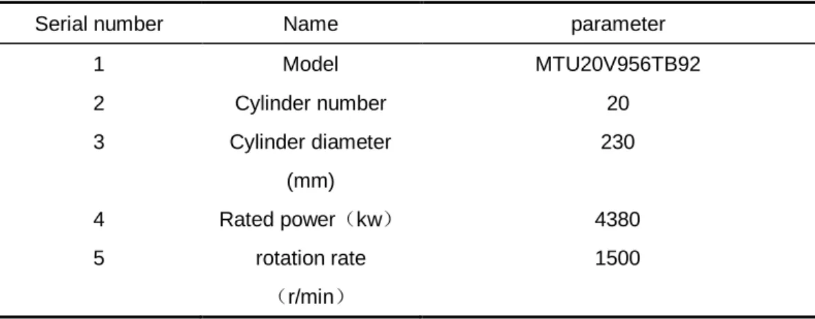
In this paper, MTU20V956TB92 is taken as the research object. It is a four-stroke direct-injec-tion water-cooled turbocharged diesel engine with medium V configuration. Its basic parame-ters are as follows.
Table 1-1 Basic Parameters of Diesel Engines
Serial number Name parameter
1 Model MTU20V956TB92
2 Cylinder number 20
3 Cylinder diameter
(mm)
230
4 Rated power(kw) 4380
5 rotation rate
(r/min)
1500
2.1 Mathematical Model of Cooling Lubricat-ing Oil System
The cooling of lubricating oil is mainly accom-plished by countercurrent heat transfer between
state of diesel engine.
Figure 1-1 Heat transfer diagram of cooling lubricating oil system
By heat transfer equation:
1 3 1
1 1
[ ( )]
yo
low l lo i
dt
T m c t t
d =W R − − (1-1)
i
t:Temperature of Low Temperature Freshwater
Intake Cooler; tyo:Temperature of low
tempera-ture fresh water outlet cooler; mlow:Mass Flow
of Low Temperature Freshwater; W3: Thermal Capacity of Freshwater Side at Low Tempera-ture; R1: Heat Transfer and Thermal Resistance
of Main Engine Lubricating Oil Cooler; T1: Av-erage Temperature Difference of Lubricating Oil
Cooler. The formula is expressed as the heat transferred from high-temperature oil to warm water in unit time, minus the heat carried by low-temperature fresh water, which is equal to the change of heat on the side of low-temperature water.
1 T
: Average Temperature Difference of
Lubri-cating Oil Cooler for Main Engine, is
1 ( ) ( ) ln i yo i o yo i i o
t t t t T t t t t + − + = − −
油 油
油
油
(1-2)
i
t油 : Lubricating oil inlet cooler temperature; t油o:
滑油出冷却器温度; tyo :低温淡水出冷却器温度;
i
t : Temperature of Low Temperature Freshwater
Intake Cooler. From top to bottom:
1 4 1 1 1 [ ( ) ] o i o dt
m c t t T
d =W − −R
油
油 油 油 油 (1-3)
4
W : Thermal Capacity of Lubricating Oil Side;
c油: Specific heat of lubricating oil.
The formula is expressed as the change of the
transfer mathematical models of the main en-gine lubricating oil cooler.
2.2 Mathematical Model of Cylinder Liner Cooling Water for Main Engine
Diesel engine is one of the main cooling parts of cooling water system. The cylinder liner of die-sel engine is cooled by cooling water to keep its working temperature within a certain range, so
as to keep the diesel engine in a sustainable working state. Figure 1-2 shows the heat trans-fer schematic diagram of the cylinder liner of a diesel engine, in which the excess heat gener-ated by the combustion of the diesel engine is transferred to the cylinder liner. The difference between this part of heat and the heat carried by the cooling water is the heat change of the diesel engine [5]
Figure 1-2 Diagram of Heat Transfer in Cylinder Liner of Diesel Engine
2
2 1
( ) ( )
in out
dt
W Q Q Q t mc t t
d = − = − − (1-4)
W: Total Heat Capacity of Cooling Water and
Cylinder Liner in Cylinder Liner, W =Mc+M c0 0;
M : Cooling water in cylinder liner; M0: Quality of Cylinder Liner; c : Specific heat of cooling
water; c0 : Specific heat of cylinder liner; m : Mass Flow Rate of Cylinder Liner Cooling Water;
1
t : Inlet temperature of main engine cylinder
liner cooling water; t2 : Outlet temperature of main engine cylinder liner cooling water; Q t( ):
Heat transfer from diesel engine combustion to cooling water per unit time.
This paper assumes that the cooling water can take away the heat in the cylinder of a diesel engine in a fixed proportion d(d=20%) is:
* * *
( )
3600
e
d P b
Q t = (1-5)
P: Host power, unit: Kw;be: Fuel consumption
rate, unit: Kg Kwh/ ; : Low calorific value of
fuel, unit: KJ Kg/ ;
In the belt-in type (1-5), there are:
2
2 1
* * *
3600
e
d P b
dt mc mc t t
d W W W
= − + (1-6)
Formula (1-6) is a simplified thermodynamic mathematical model for the cooling of the main engine cylinder liner.
2.3 Mathematical Model of Visceral Block-age in Seadoor Filter
The submarine door filter is mainly used to block
cal resistance loss, that is: 2 2 j U h g
= (1-7)
U: Average Velocity of Seawater in Pipeline(m/ s); : resistance coefficient. The inlet and outlet
pressure of the filter is calculated by Bernoulli equation.
2 2
1 1 2 2
1 2
2 2 j
P U P U
Z Z h
g g g g
+ + = + + + (1-8)
Among them: the height of section position Z1 and Z 2, the pressure of section position P1 and section position P2, respectively; is the den-sity of sea water.
The relationship between fluid velocity Q and flow rate U in pipeline can be expressed by the following formula: 12 2 4Q U d
= (1-9)
Substitute (1-7) and (1-8) into (1-9) and take into
accountZ1=Z2,U1=U2, Then the following form-
ula can be obtained:
2
1 2 2 4
8 Q P P d − =
(1-10)
2.4 Mathematical Model of Water Pump
Water pump is an important part of marine die-sel engine cooling system. The normal operati-
on of water pump is an important guarantee of the system. The characteristic equation of the pump is as follows:
2
0 1 2
H =K +K Q+K Q (1-11)
0
K : Pressure Head at No Load; K1: Dynamic
Pressure Loss Coefficient of Pump; K2: Pres-sure loss constant of pump itself; H : Pump lift unit : m3/s
( K0、K1、K2 is the fixed parameter
index of the pump)
When choosing the mathematical model, the pumps are classified according to the specific speed, which is defined as:
0.5 0.75 s NQ N H =
(1-12)
N:rotation rate, unit: rpm;
3. Implementation of the system
3.1 Main Structure Design of the System
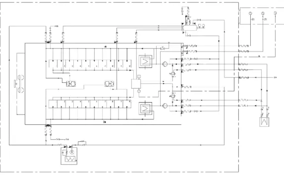
Through drawing software to draw the water
component technology to increase the reusabil-ity of code to meet the design requirements of the system. The system is mainly composed of seawater system, freshwater system and fault simulation system. Each subsystem has the functions to be realized by each subsystem.
Each function needs to establish links with the database, read data from each other, and then appear on the system interface. The structure flow chart of the system is shown in Fig. 2-3, and the arrangement of the freshwater system in the design process is shown in Fig. 2-2.
Figure 2-1 Schematic diagram of cooling water system structure
Figure 2-2 Freshwater Interface Layout of the System
3.2 Data linkage in the system
In the system, the relevant parameters of each component are constantly changing, and the parameters of other parts of the system will
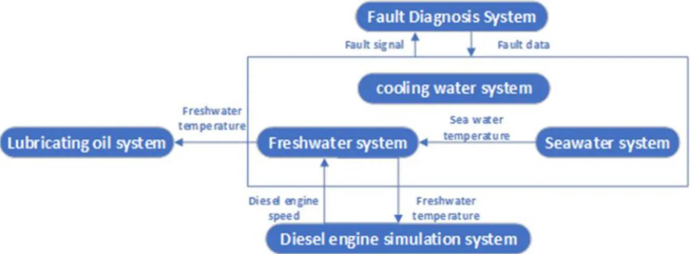
the logical control model, and finally the real-time parameters of the mathematical model are displayed [7]. Figure 2-3 shows the block dia-gram of information exchange between cooling
water system and other systems. The system uses PID control [8] [9]. Figure 2-4 shows the block diagram of PID control algorithm.
Figure 2-3 Information Interaction between Cooling Water System and Other Systems
3.3 Design of database in fault simulation
In this system, the trainees can simulate the faults by injecting the faults into the system in-terface. In the design process, I have edited and arranged the specific parameters correspond-ing to the faults in an Excel table. After the faults
are injected, the data can be invoked. The curr- ent fault parameters can be displayed in the system interface to simulate the faults of the cooling water system.
Figure 2-4 Structure of Excel database
4. Examples of System Fault Simulation
There are many kinds of faults in this system, and the system can be changed slightly accord-ing to the need. The followaccord-ing two examples are the abrasion of seawater pump and the block-age of submarine door to show the effect of the system after completion.
4.1 Wear Failure of Seawater Pump
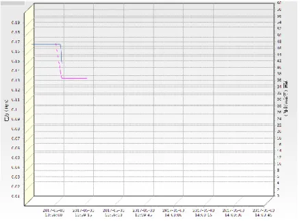
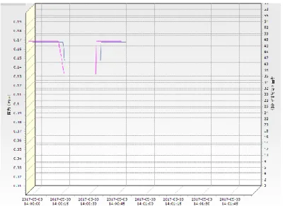
Figure 3-1 shows the normal wear failure dis-play interface of seawater pump. It can be seen from the chart that the pressure of the return pump is stable at about 0.16 MPa and the flowrate of the pump is about 50 m3/h. After
common wear and tear failure, the pressure and flow rate of the sea water pump begin to de-crease. After a period of time, the flow rate of the pump drops to about 39 m3/h and the pres-sure of the pump drops to about 0.14 MPa. If there is no other operation, the fault will con-tinue, and because of the correlation of mathe-matical models [10], if the oil cooler is selected as the measuring point, the cooling water tem-perature will increase. If other relevant measur-ing points are selected, the data of other meas-uring points will change accordingly.
Figure 3-2 shows the process of seawater pump from normal operation to medium wear and then to reset. It can be seen from the graph that when the common fault of the seawater pump is reset, the fault will be eliminated immediately and the
flow and pressure will return to normal condition. The countermeasure of breakdown: Start an-other group of seawater pumps to check and re-pair the breakdown seawater pumps.
Fig. 3-2 Reposition of Common Wear Failure of Seawater Pump
4.2 Blockage failure of submarine door
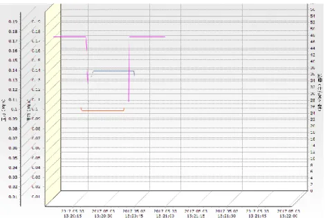
Figure 3-3 shows the result of the blocking fail-ure of the submarine door. It can be seen from the graph that the pressure difference before the submarine door filter is about 0.12 MPa, the pressure behind the filter is about 0.1 MPa and the flow rate is about 50 m3/h when the subma-rine door filter is in normal operation. After the blocking failure of the submarine door, the pres-sure difference before the submarine door filter rises to about 0.125 MPa, the pressure after the
filter decreases to about 0.95 MPa, and the flow rate of the submarine door decreases to about 30 m3/h in a straight line. If the fault will continue, the water temperature of the cylinder liner of the main engine will be selected as the measuring point because of the correlation of the mathe-matical model, and the water temperature will rise rapidly. If other relevant measuring points are selected, the data of other measuring points will also change.[11]
Figure 3-4 simulates the process of submarine door blockage from normal operation to reset af-ter blockage failure. It can be seen from the graph that when the submarine door is blocked and reset, the fault is eliminated, and the flow and pressure of the submarine door filter before
and after return to normal value. The counter-measure for blocking failure of submarine doors: timely inspection and cleaning of submarine doors, and opening another submarine door if conditions permit.
Figure 3-4 Seabed Gate Blockage Failure Reset
5. CONCLUSION
1) The mathematical model is established by the actual working parameters of the cooling water system of marine diesel engine, and the working state of the cooling water system of MTU20V956TB92 diesel engine is simulated by using the platform of Visual Studio 2012. The simulation results are close to the real ship, which shows the accuracy and rationality of the establishment process, and provides a basis for developing similar diesel engine fault simulation system. Definite reference value. 2) The simulation system breaks through the limitation of time and site. Through this system, the operators can be trained in ship cooling wa-ter system, and the training efficiency of the trainees can be improved, the training cost can be reduced, and the trainees'ability to judge the cause of the cooling water system failure can be improved.
Reference documentation
1. Wang Gongsheng. Working process simulation
and fault simulation of marine low-speed two-stroke diesel engine [D]. Dalian Maritime Uni-versity, 2010.
2. Shang Qianming, Wang Ruihan, Chen Hui,
Tang Xinfei. Application of multi-information fu-sion technology in fault diagnosis of marine die-sel engine [J]. China Navigation, 2018 (03): 26-31.
3. Wang Xiaomei. Development of monitoring and
diagnosis system for marine diesel engine
op-eration [D]. Shanghai Jiaotong University, 2011.
4. Zhang Qiaofen. Mathematical model of marine
diesel propulsion system under multi-operating conditions and marine engine operation evalua-tion system [D]. Dalian Maritime University, 2016.
5. Yuan Yunfei. Research on Intelligent Fault Di-agnosis Strategy of Marine Diesel Engine Lubri-cation System [D]. Jiangsu University of Sci-ence and Technology, 2015.
6. Huang Jialiang, Xie Gang. Thermal Fault
Simu-lation of Marine Diesel Engine Based on BOOST [J]. Ship Science and Technology, 2015, 37 (1): 69-74.
7. Chen Jian. Mathematical modeling and
937-942.
8. Qian Yuehua, Gong Dao, Zhu Jun.
Develop-ment and application of real-time simulation model for marine low-speed diesel engine [J].
Marine Engineering, 2017, 39 (06): 20-23. 9. Xiao Wenjian, Li Yongke. Intelligent vehicle
de-sign based on incremental PID control algorithm [J]. Information technology, 2012, 36 (10): 125-127.
10. Gu Linlin, Zhang Jundong. Simulation of diesel engine electronic governor based on fuzzy PID controller [J]. Journal of Dalian Maritime Univer-sity, 2014, 40 (01): 57-60+65. 11. Ling Shuangming. Fuzzy PID adaptive control