http://www.sciencepublishinggroup.com/j/ajche doi: 10.11648/j.ajche.20200801.15
ISSN: 2330-8605 (Print); ISSN: 2330-8613 (Online)
Study on the Performance of a Swirl Tube Column
M. Jiang, H. Yuan, S. Fu, Q. Shi
Institute of Separation Engineering, Changzhou University, Changzhou, P. R. China
Email address:
To cite this article:
M. Jiang, H. Yuan, S. Fu, Q. Shi. Study on the Performance of a Swirl Tube Column. American Journal of Chemical Engineering. Vol. 8, No. 1, 2020, pp. 27-35. doi: 10.11648/j.ajche.20200801.15
Received: March 14, 2020; Accepted: March 26, 2020; Published: April 13, 2020
Abstract:
A column is an important heat and mass transfer equipment, which can be used for distillation, absorption, gas stripping, extraction and other transfer separation process. The commonly used columns include plate columns and packed columns, which are operated under the gravity and have the problems of flooding, furrow flow or bias flow. In this paper, a new column, the swirl tube column, is presented. The swirl tube column is firstly combined super-gravity field (centrifugal force field) with column equipment to enhance mass transfer and absorption process. Through the full-field simulation of a two-stage swirl tube column and experiment, the fluid mechanics performance such as the velocity field and pressure field, pressure drop and flooding critical condition in the swirl tube column, as well as the influence of flowrate and gas-liquid ratio on the absorption performance are studied. Results show that the swirl tube in the column can generate swirling flow, and the flooding problem can be effectively avoided by properly controlling the ratio of liquid to gas, and the absorbing efficiency of the one-staged swirl tube column can reach more than 61%. It is an innovation structural optimization of traditional column equipment. Which has high research and industrial production value.Keywords:
Column Equipment, Swirl Tube Column, Swirl Tube, Super-gravity Field, Fluid Mechanics Performance, Flooding, Absorbing Efficiency1. Introduction
Columns can be used for closing contact between gas-liquid or liquid-liquid phases to achieve the purpose of transfer and separation of components such as distillation, absorption, desorption, extraction drying and so on. The commonly used columns include plate columns and packed columns. The plate column is mainly composed of a cylindrical column body and a plurality of horizontal trays, and the gas-liquid contact mass transfer mainly occurs on the tray plate. The packed column is a mass transfer device with a packing in the column as a two-phase contact member. In recent years, people have made many improvements to the structure of column equipment in order to improve the unit separation efficiency of distillation, absorption and desorption et al. Hosanna Uwitonze et al. [1] proposed a design method for determining the structure of a traditional two-product column and a Petlyuk column. Compared with the conventional rectification column, the fully thermally coupled rectification column has certain advantages in terms of energy saving and capital cost saving. However, he mainly considered energy saving and cost saving,
down the column wall, through the overflow device to the next tray, and again atomized by the gas stream for gas-liquid contact. They claim this swirling plate column not only having advantages of a large gas-liquid circulation, low pressure drop, wide operational flexibility, high absorption efficiency, but also has the advantages of dust removal, easy to block and the stabilization efficiency advantages. However, such column equipment has uneven flow throughout the cross section, the larger the column diameter, the more uneven the distribution, and the limited centrifugal force generated by the rotation of the gas, the larger the column diameter, the smaller the effect. Therefore, the application of the swirling plate column is limited.
The cyclone is a common separation device. The fluid is introduced into the cyclone from the sidewall in a tangential direction or through a spiral blade. The high-speed rotation produces a centrifugal force field to enhance the phase separation process. At the same time, the strong turbulence and shear force generated by the swirling flow can tear the liquid into liquid film, liquid filament and droplet, which increases the specific surface area of the two-phase contact, and accelerates the molecular diffusion and phase-to-phase mass transfer process compared with the conventional DC state. Near the axis of the cyclone, the velocity gradient in the swirl field is large, causing the liquid phase to increase sharply in a narrow range, causing a sharp turbulence in the liquid phase of the region. The degree of turbulence near the wall is also enhanced, which is caused by collision and friction between the high-speed rotating fluid and the wall, which promotes the breakage of the particles and forms a large and constantly updated contact surface, thereby strengthening the mass transfer process [5]. The cyclone has a simple structure, small volume and small footprint, and low cost. Therefore, many scholars at home and abroad have explored the application of heat transfer, mass transfer and separation processes between heterogeneous or multiphase. For example, Romuald P et al. [6] designed and manufactured an air-jet hydrocyclone and injected sulfur-containing exhaust gas into the swirling alkaline absorption liquid. The centrifugal field generated by the swirling flow greatly enhanced the desulfurization process and thus improved Desulfurization effect, the absorption efficiency can reach more than 99%, and it has been successfully applied to the desulfurization process of American smelting companies. K. H. Javed [7] uses swirling gas flow to enhance the mass transfer performance of the spray column.
These are single-tube cyclone operations, while single-tubes ensure mass transfer and separation efficiency of the two phases, but the flowrate is limited. If the single tube diameter is increased to increase the flowrate, mass transfer efficiency and phase separation efficiency are affected. The combination of multiple tubes not only increases the flowrate but also ensures the efficiency of two-phase mass separation. Therefore, the research on multi-tube combination, such as parallel and series, is very important.
This paper combines a cyclone and a column device to form a new type of supergravity column equipment. The device can
complete the transfer process and the phase separation process at the same time, and has the characteristics of high transfer efficiency, avoiding flooding, and large processing capacity per unit volume of equipment.
The performance of the swirl tube column includes transfer performance, phase separation performance and hydrodynamic performance. In this paper, the two-phase flow field distribution, hydrodynamic characteristics and absorption performance in the swirl tube column are studied by experiments and CFD numerical simulation.
2. Basic Structure and Principle of the
Swirl Tube Column
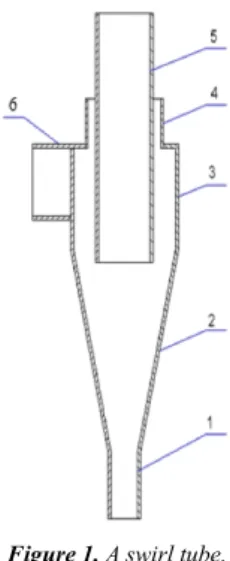
The swirl tube column is a plate column with a swirl tube as the transfer element in the column (Figure 1). The swirling mass transfer element, referred to as the swirl tube, is improved on the original cyclone structure (Figure 2), including the cylindrical conical swirl tube, the tangential inlet, the overflow outlet, the annular inlet opened outside the overflow outlet, and bottom outlet. In the cyclone column, the tray is transformed from a conventional mass transfer and heat transfer site to a platform carrying a swirl tube. The transfer process is not carried out on the tray but in a swirl tube on the tray. The traditional flow field of the entire column section is divided into a plurality of micro-swirl fields. Because the swirling mass transfer element in the swirl tube column can not only fully mix the two-phase materials and improve the phase interface renewal rate by the turbulent action of the combined vortex, and strengthen the dispersed phase sedimentation process by using the super-gravity field (centrifugal force). Therefore, the swirl tube column has a good transfer effect and high phase separation efficiency. In addition, due to the supergravity characteristics of the cyclone field, no flooding occurs in the column; due to the forced uniform arrangement of the swirling tubes, no channeling or drifting occurs in the column; since the swirling separation of the swirling tube is continuous separation The process is not easy to block even if solid precipitates are generated; due to the swirling characteristics in the swirling mass transfer element and easy to satisfy the transfer efficiency and the flowrate by series and parallel connection, the swirl tube column is easy to amplify. A plurality of swirl tubes are connected in parallel to form a tray layer, and the first stage transfer is completed to achieve a certain flowrate requirement. The multi-layer trays are connected in series to form an integral transfer device to achieve a certain transfer effect requirement.
bottom outlet, and then goes down to the next-stage swirl tube for further transfer. The light phase migrates toward the center of the swirl tube, and finally exits from the swirl tube overflow outlet, goes up to the upper-stage swirl tube for further transfer, and finally discharges from the top of the column. In the swirl tube, the heavy phase (usually the liquid phase) enters the swirl tube through the annular inlet around the overflow tube, and through the swirling action, the heavy phase forms a liquid film, a liquid filament or even a droplet, increasing the light and heavy two phases. In the swirl tube, the heavy phase (usually the liquid phase) enters the swirl tube through the annular inlet around the overflow tube, and the liquid phase, liquid filament or even droplets are formed by the swirling action to increase the Specific surface area of light and heavy two-phase contact. And because the liquid phase moves to the wall of the swirling tube under the action of centrifugal force, the relative velocity of the two phases increases, and the interface renewal rate of the light and heavy phases is improved, thereby strengthening the phase separation process and the transfer process.
Figure 1. A swirl tube.
1-bottom outlet, 2-cone section, 3-colum section, 4- annular inlet, 5-overflow outlet, 6- tangential inlet
Figure 2. Swirl tube column.
As a new type of supergravity enhanced transfer equipment, the swirl tube column can be used for various transfer processes between various materials, such as absorption, stripping, extraction, distillation, and the like.
3. Methods
3.1. Experiment Method
3.1.1. Materials
Feed materials: air mixed with CO2, whose volume
concentration is 1.5%.
Absorption liquid: NaOH solution, with the concentration of 0.5mol/L.
The concentration of CO2 of gas flow were analyzed by an
austenitic gas analyzer.
3.1.2. Test Rig and Its Operation
In this section, a single-tube two-stage swirl tube column test device as shown in Figure 3 is constructed according to experimental requirements and laboratory conditions. The flow chart of the Test rig is shown in Figure 4. The NaOH was formulated into a 0.5 mol/L solution, and about 250 L (which can satisfy the continuous experiment for 15 minutes) was stored in the reservoir. Turn on the annular blower and adjust the air flow Q to 100 m3/h. The flowrate of CO2 from the
cylinder could be adjusted to keep the CO2 concentration at
around 1.5%. After the mixed gas is configured, the centrifugal pump is started to drive the NaOH solution into the swirl tube column. During this process, the readings of each meter are closely observed, recorded one by one, and the gas at the overflow is sampled and placed in a numbered sampling bag. After the end of the experiment, the flowrate of CO2 and
the blower is calibrated, and the amount of the intake air and the amount of the liquid are changed accordingly.
Figure 4. Experimental flow chart.
R is storage container; P1 is centrifugal pump; P2 is blower; V is valve; P is pressure gauge; F is flowmeter.
To investigate the effect of flowrate on its absorption, the gas-liquid ratio, the CO2 concentration 1.5% and the NaOH
concentration 0.5mol/L is kept to be unchanged. To investigate the effect of the gas-liquid ratio on absorption, the feed flowrate, the CO2 concentration 1.5% and the NaOH
concentration of 0.5 mol/L are basically unchanged.
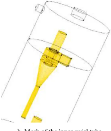
a. swirl tube column mesh
b. Mesh of the inner swirl tube
Figure 5. Meshing of a swirl tube column.
3.2. Numerical Simulation Method
3.2.1. Physical Models and Meshing
Due to the complicated structure of the analog whole column equipment, it is necessary to draw a large number of mesh, it takes up too many resources of the computer and it is difficult to perform a more accurate simulation. Therefore, we simplify the structure of the swirl tube column as shown in Figure 5. One plate is equipped with a 50 mm diameter swirl tube, and two layers of plates are connected in series, and the cylinder diameter is 200 mm.
Using GAMBIT to model and mesh, the structure of the swirl tube in the column is divided by high-quality structural mesh, and the outer cylinder is divided by unstructured mesh. As shown in Figure 6.
3.2.2. Model Calculation and Boundary Conditions
Using the simulation software ANSYS 15.0, the finite volume method is used as the calculation method, the turbulence model is selected by the Reynolds stress model (RSM), the multiphase flow model is selected by the Euler-Eulerian model, and the population balance model is loaded. Among them, the Luo model is selected by the aggregation and fragmentation of the droplets. Turn on the component transport model, set up mixing multi-component, and turn on the interphase chemical reaction. The pressure-velocity coupling term in the governing equation is selected by the Phase Coupled SIMPLE algorithm, Select PERSTO pressure complement format. The discrete method of the other items selects the QUICK method, and the double precision solver is used to improve the calculation accuracy.
3.2.3. Selection of Turbulence Model
For the strong rotating flow in the swirl tube [8], the Reynolds stress model which is more advantageous in simulating the anisotropy of the turbulent flow field is selected [9]. For incompressible fluids, the governing equation is [10] (Reynolds-averaged Navier-Stokes), which can be expressed as:
+ ρ = 0 (1)
= " + ′ # = 1, 2, 3 (3) Where ) = !!!!!!!′ ′ is the average Reynolds stress (Pa),
μ is the hydrodynamic viscosity + ∙ -// , is the velocity vector (m/s). In order to close the control equation, the RSM model is used to calculate the transport equation:
0
+ 1 = −23, + 24, − 5 − 6 + ∅ − 8 − 9 (4)
Where 1 , −23, , 24, , 5 , 6 , ∅ , 8 , 9 are convection term, turbulent diffusion term, molecular viscous diffusion term, shear stress generation term, buoyancy generation term, pressure strain term, viscous dissipation term and system rotation generation term [11].
3.2.4. Boundary Conditions
The boundary conditions are set as follows:
(1)Inlet boundary conditions: the gas phase liquid inlets of the swirl tube column are set as velocity inlets, which are perpendicular to the inlet cross section, and the flow rate is converted according to the treatment amount. The hydraulic diameter is calculated according to the relevant formula, and the turbulence intensity can be calculated according to the formula (5).
I = 0.16 Re2? @ A
B (5)
where Re is Reynolds number, DH is Hydraulic diameter (m).
The inlet speed simulated below is 0.8m/s in the liquid phase and 2m/s in the gas phase; the input amount is 0.6m3/h in the liquid phase and 9m3/h in the gas phase.
(2)Outlet boundary conditions: Exports are all set as pressure outlets.
(3)The inner wall of the swirl tube inside the swirl tube column includes an axial side wall and a top end inner wall, be processed without slip, and other parameters remain the default.
3.2.5. Component Transport Model and UDF
Turn on the component transport model and set the mixture components. The heavy phase is a NaOH solution, and the light phase is air containing a certain CO2 concentration. A
chemical reaction is added between the two phases, and the basic reaction equation is 2NaOH + CO2 = Na2CO3 + H2O.
The reaction rate was defined using the HET_RXN_RATE macro in UDF, and the simulated reaction rate was set to the immediate reaction of gas-liquid two-phase contact.
4. Results and Discussion
4.1. Two-phase Flow in the Swirl Tube Column
Similar to a plate column, the two-phase flow in the swirl tube column is also a complex phenomenon. Under the action of gravity, the liquid flows through the swirling tubes of the various stages from top to bottom, and is discharged to the bottom of the column; under the push of the pressure difference, the gas passes through the swirling tubes of each stage from bottom to top and is discharged to the top of the
column. The liquid is rotated by the gas in the swirl tube to carry out the phase contact mass transfer. The swirl tube column divides a large swirling flow field of the traditional swirling column into several small swirling fields. Through the multi-layer swirling tube, the principle of centrifugal sedimentation is used to achieve multi-layer purification. Therefore, the main flow mass transfer region of the gas-liquid two phase is in the swirl tube.
4.1.1. Pressure Field
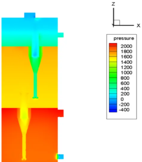
Figure 6 is a contours of pressure within the swirl tube column. It can be seen from Figure 6 that the pressure in the single-layer tray space gradually decreases from top to bottom; the multi-stage series tray space has a significant decrease in pressure, the space pressure in the uppermost layer is the smallest, and the pressure in the lowermost layer space is the largest. The pressure field distribution of the cyclone in the swirl tube column is basically similar to that in a single swirl tube. As the radial position increases, the pressure value increases and reaches a maximum at the wall surface. The value is small at the position of the overflow outlet and the bottom outlet, and even the bottom outlet may have a negative pressure, that is, an air column is generated. After the fluid enters the swirl tube, the pressure energy is converted into kinetic energy, and the high-speed rotational motion of the fluid is achieved, and the pressure distribution is stable, indicating that the flow field in the component is stable, which is advantageous for the mass transfer and separation process.
4.1.2. Velocity Field
As shown in Figure 7, the gas phase enters the column from the light phase inlet of the swirl tube column, and then enters the swirl tube from the tangential inlet of the swirl tube to drive the liquid swirling which flowing down from the upper tray. After gas-liquid mass transfer and separation, the gas phase flows out of the overflow outlet to the upper tray, and then enters the upper swirl tube from the tangential inlet and drives the liquid phase flowing down from the top layer to rotate. The two-stage mass transfer separation is completed as a whole, and the velocity field basically conforms to the idea of the beginning of the design.
Figure 7. Velocity vectors of swirl tube column.
4.2. Hydrodynamic Characteristics of the Swirl Tube Column
The hydrodynamic performance of the swirl tube column mainly refers to the flow state of the gas-liquid two phases in
the swirl tube, and various factors affecting the mass transfer and separation performance of the swirl tube, such as the pressure drop, the split ratio and the operating parameters.
4.2.1. Two-phase Distribution
Figure 8a is cloud chart of liquid phase distribution in outer tube. It can be seen from the figure that the gas-liquid two-phase layering is relatively obvious, and a liquid of a certain height is accumulated on each layer of the tray. The liquid entering the lower tray from the upper tray needs to overcome the pressure difference ∆P between the trays. Figure 8b is a Y=0 cross-sectional view, and each of the trays in Figure 8 has a certain height H of hydrops. The height not only provides a static head for the liquid to enter the lower tray but also seals the bottom outlet and the annular inlet, so that let the tangential inlet of upper swirling tube to be the only path which the gas coming out of the lower overflow outlet can enter. The formula for simply calculating H is
ρgh = ∆p (6) The calculated H is 20mm, which basically conforms to the actual simulated result.
Figure 8.Cloud chart of liquid phase distribution in the swirl tube column.
4.2.2. Pressure Drop
The pressure drop of the swirl tube column is an important performance index to measure the performance of the swirl tube column. It is directly related to the energy consumption of the operation process, the determination of operating conditions and other issues. The pressure drop of the gas through the swirling tubes of each layer of the tray directly affects the velocity distribution and pressure distribution in the
swirling tube, which in turn affects the mass transfer performance, separation performance and the flowrate of the swirling tube.
The energy needs of the swirl tube in the swirl tube column are manifested by the need for its driving force and pressure drop. The pressure drop is usually expressed by the static pressure loss at the inlet and the overflow, ie
o
P
P
P
=
−
2
2 i
k
8
=
∆
D
Q
P
π
ρ
(8)where
Q
i is feed flow rate (volume),D
is the norminal diameter of the swirl tube,ρ
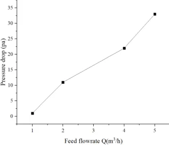
is medium density and k is constant.Figure 9. The relationship between pressure drop and feed flowrate. As shown in Figure 9, the pressure drop increases as the flowrate increases. Due to the rotation of the fluid in each stage of the swirling tube in the column and the generation of sufficient centrifugal force, the pressure drop of the swirling column is greater than that of conventional column equipment [12], but it is lower than that of other supergravity columns, and simple structure. [13]
4.3. Absorption Performance of the Swirl Tube Column
The absorption efficiency is to characterize the absorption effect of the gas-liquid absorption device. Generally, for gas purification, the absorption effect can be directly expressed as the solute molar ratio at the outlet, and if a gas is used, the formula (9) can be used.
E = 1 − 1H/1 (9) where
I is Working temperature (K);
R is Molar gas constant, 8.314J/(mol * k);
1 is Swirling tube inlet CO2 volume fraction 1H is Swirling tube outlet CO2 volume fraction
J is The molar ratio of CO2 in the inlet of the swirling tub
column is determined by equation (10);
JH is The molar ratio of CO2 in the outlet of the swirling tub
column is determined by equation (11);
Since the characteristics of the actual gas at low pressure are close to the ideal gas, the volume fraction is equal to the mole fraction, so the relationship
between the molar ratio and the volume fraction is
J =L@KK (10)
JH=L@KKMM (11)
4.3.1. Effect of Feed Flowrate on Absorption Efficiency
According to formula (9), combined with the test data and the simulation data, the chemical absorption efficiency of the swirl tube column at different treatment amounts can be calculated.
Figure 10 is a graph showing the relationship between the amount of gas treatment and the absorption efficiency of a two-stage swirl tube column with the gas-liquid ratio remaining substantially constant (20: 1). In general, the efficiency curve has a decreasing trend. When the flowrate is between 30m3/h and 40m3/h, the absorption efficiency changes from decreasing to increasing, and 40m3/h reaches the maximum absorption efficiency of 80%. After 40m3/h, The absorption efficiency decreases faster.
Figure 10. Absorption efficiency as a function of feed flowrate.
Figure 11. Liquid flow distribution at the top of the swirl tube tower. The reason for the phenomenon of Figure 10 is that the
5 10 15 20 25 30 35 40 45 50 55 60 65 0
10 20 30 40 50 60 70 80 90 100
Ab
so
rp
it
on
e
ff
ic
ie
nc
y
(%
)
Flowrate (Q (m3/h))
absorption of CO2 in the swirl tube in the swirl tube column is
affected by two factors: residence time and absorption rate. When the flowrate is small, the residence time is longer and becomes the main factor affecting the absorption efficiency, so the absorption is relatively sufficient; When the flowrate is large, the relative velocity of gas and liquid becomes larger, the droplet breakage increases, the contact surface becomes larger, and the thickness of the gas-liquid film becomes thinner, so that the rate of absorption becomes larger, and thus the absorption rate becomes a major factor affecting the absorption efficiency. However, in this case, the time of the radial and axial motion characteristics of the droplets in the swirling field is reduced, resulting in a decrease in the effective contact time of the two phases, which may result in a weakening of the absorption effect.
In Figure 10, the flowrate starts from Q = 30m3/h to 40m3/h, and the absorption efficiency starts to increase. This is because the increase rate of the absorption rate starts to increase from the flowrate Q=30m3/h, and the influence of the residence time on the decrease of the absorption efficiency is weakened to some extent, so that the absorption efficiency starts to increase. After the treatment amount Q=40m3/h, the absorption efficiency decreases sharply. As can be seen from Figure 11, since the swirling tube column body is small, the flowrate gradually becomes larger under the condition of a certain liquid-gas ratio, so the heavy phase is progressively increased and the amount of heavy phase gradually becomes larger than the amount entering the annular inlet. Therefore, the top of the swirl tube will be filled so that the heavy phase has no way to enter the lower layer of the swirl tube and the gas for mass transfer, resulting in a sharp decrease in absorption efficiency. In general, the absorption efficiency of the two-stage swirl tube column studied by the light simulation experiment can reach 82% when the treatment volume is Q=40m3/h.
4.3.2. Effect of the Gas-liquid Ratio on Absorption Efficiency
According to formula (9), combined with the test data and the simulation data, the chemical absorption efficiency of the swirl tube column at different gas-liquid ratios can be calculated. Figure 12 shows the absorption efficiency of the two-stage swirl tube column as a function of liquid-gas ratio. The absorption efficiency increases as the liquid-gas ratio increases. Because the liquid mass transfer coefficient decreases as the liquid-gas ratio increases, the more the CO2
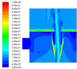
absorption in the gas phase is absorbed by the liquid phase of the experiment as the chemical absorption, that is, the more sufficient the absorption. When the liquid-gas ratio is less than 0.05, the absorption efficiency drops sharply as the liquid-gas ratio decreases. There are two reasons for this problem: (1) The liquid phase has too little chemical absorption and absorbs saturation. (2) As shown in Figure 13, since the amount of intake air is much larger than the amount of liquid intake. The cause is gradually flown into the liquid phase of the bottom tray by gravity from the top tray, and is blown back by the gas phase from the bottom layer, causing a problem of flooding. Therefore, controlling the liquid-gas ratio above
0.05 can effectively avoid the problem of flooding.
Figure 12. Absorption efficiency as a fuction of iquid-gas ratio.
Figure 13. Liquid phase distribution cloud map with liquid flooding problem. From the experimental and simulation results, the single-stage absorption efficiency of the swirl tube column can reach 70%, which is much larger than 20%-40% of the traditional gravity field equipment. The absorption efficiency of the two stages can reach 80%-90%.
5. Conclusions
The swirl tube column is an innovative design proposed by the authors. It replaces the mass transfer element in the traditional column with a swirl tube, and uses the supergravity field to strengthen the transfer process and the phase separation process, and could meet the requirement of processing capacity and efficiency through varying the number of swirl tubes and stages respectively. As long as the simple control of the treatment volume and liquid-gas ratio can effectively avoid the flooding, channeling and other problems that are likely to occur in traditional column equipment. The one-stage efficiency of the cyclone tube column could reach 61%, which is significantly higher than that of a traditional column with about 40%. The swirl tube
0.0 0.1 0.2 0.3
column is expected to be a "transistor" in the history of the column equipment industry.
Through the simulation and experiment, conclusions could be drown as follows.
(1)In the case of a certain gas-liquid ratio, the treatment amount is controlled under 40m3/h. With the increase of the treatment amount, the absorption efficiency is slightly decreased and then increased, which is basically maintained between 75% and 80%.
(2)When the liquid-gas ratio is increased under a certain flowrate, the liquid-gas ratio is controlled to be greater than 0.05, and the absorption efficiency increases as the liquid-gas ratio increases.
(3)The pressure drop of one stage the swirl tube column is higher than that of conventional columns, but the total pressure drop could be maintained in an acceptable range due to the small number of stages of the swirl tube column.
References
[1] Hosanna Uwitonze, Kyu Suk Hwang, Inwon Lee. A new design method and operation of fully thermally coupled distillation column [J]. Chemical Engineering & Processing: Process Intensification, 2016, 102.
[2] Toshihiro Wakabayashi, Alessandro Ferrari, Shinji Hasebe. Design and commercial operation of a discretely heat-integrated distillation column [J]. Chemical Engineering Research and Design, 2019.
[3] Meng Tang, Shaofeng Zhang, Dewu Wang, Yan Liu, Lusha Wang, Chen Liu. Experimental study and modeling development of pressure drop in concurrent gas-liquid columns with a tridimensional rotational flow sieve tray [J]. Chemical Engineering Science, 2018, 191.
[4] Tianen Tan, Dazhao Wang, Yizhong Jin. Application of Swirl Plate Tower and Its Recent Research Progress [J]. Petrochemical Equipment, 1991 (2): 13-16. (In Chinese) [5] Huixin Yuan, Biao Feng. Separation Engineering [M]. Beijing:
China Petrochemical Press, 2001.145-147. (In Chinese) [6] Bokotko R P, Hupka J, Miller J D. Flue gas treatment for SO2
removal with air-sparged hydrocyclone technology. [J]. Environmental Science & Technology, 2005, 39 (4): 1184-1189.
[7] Javed K H, Mahmud T, Purba E. Enhancement of Mass Transfer in a Spray Tower Using Swirling Gas Flow [J]. Chemical Engineering Research & Design, 2006, 84 (6): 465-477.
[8] Pericleous K A, Rhodes N. The hydrocyclone classifier — A numerical approach [J]. International Journal of Mineral Processing, 1986, 17 (1–2): 23-43.
[9] Yongbo Shan, Yuxing Li. Prediction of cyclone separation performance by Reynolds stress (RSM) model [J]. Refining Technology and Engineering, 2005, 35 (1): 18-21. (In Chinese).
[10] Murthy Y R, Bhaskar K U. Parametric CFD studies on hydrocyclone [J]. Powder Technology, 2012, 230: 36-47. [11] Delgadillo J A, Rajamani R K. A comparative study of three
turbulence-closure models for the hydrocyclone problem [J]. International Journal of Mineral Processing, 2005, 77 (4): 217-230.
[12] Development of new towers and computational fluid dynamics and mass transfer studies [D]. Tianjin University, 2004. (In Chinese).