Volume 42 (2010)
Proceedings of the
4th International Workshop on
Multi-Paradigm Modeling
(MPM 2010)
Compliance between Architecture and Design Models of
Component-Based Systems
Sebastian Herold
12 pages
Guest Editors: Vasco Amaral, Hans Vangheluwe, C ´ecile Hardebolle, Lazlo Lengyel Managing Editors: Tiziana Margaria, Julia Padberg, Gabriele Taentzer
Compliance between Architecture and Design Models of
Component-Based Systems
Sebastian Herold
Clausthal University of Technology
Department of Informatics – Software Systems Engineering Group P.O. Box 1253, 38670 Clausthal-Zellerfeld, Germany
Abstract: The design of software systems and the models describing it are usually constrained by the intended software architecture. The intended software architec-ture defines, for example, how components may be grouped or how they may in-teract. For the sake of maintenance, evolvability, and smooth operation of software systems, it is of great importance to check and guarantee the architectural compli-ance of the design and the implementation. Due to size and complexity of modern software systems such checks cannot be done manually but require adequate tool support. Unfortunately, current tool support is not flexible enough to cover easily different aspects of architectural compliance checking.
This paper outlines an approach to architectural compliance checking in component-based systems component-based on logic formalisms. Furthermore, the paper describes a pro-totypical tool that realizes the approach, and its application in a case study.
Keywords:Architectural compliance, model consistency, component-based devel-opment
1
Introduction
According to the most broadly accepted and commonly used definitions of software architec-ture, a software architecture deals with the fundamental organization of a system, manifested in its components, relationships among them and to the environment ([IEE00]). A software archi-tecture embodies the earliest and most far-reaching design decisions for the development process and life-cycle of a software system. Errors and mistakes made during the design of the software architecture are nearly irreversible and very difficult and costly to repair [BCK05].
Due to the size and complexity of modern software systems and their development processes, it is always possible that during the detailed design and implementation of the system the in-tended architecture will be violated. As a consequence, the design decisions manifested by the architecture are not reflected in the actual system. Model-driven development (MDD)[SVC06] addresses these compliance issues partially. The software architecture of a system can be speci-fied as a model which is semi-automatically transformed and refined into a more specific design model of the system, which again could be transformed into the implementing code. If the trans-formation rules are correct, compliance between architecture model and design model or the implementation is ensured.
of software architectures. Models specifying software architectures normally consist of
inten-sionalstatements about the system. Simplified, an intensional statement defines a concept by
constraints that hold for the - potentially infinite many - instances of the concept [EHK06]. For example, from an architecture model containing a logical layer [BMR+96], we could generate a package representing the layer in the design model, but not which specific components and functionality are encapsulated by the layer. Only the intensional constraint is known, stating that components in this layer may not access components from layers above. Thus, a transfor-mation of an architectural model into a design model will create only one valid refinement of many possible ones. In practice, it will be edited manually and requires compliance checks after changes.
However, checking architectural compliance is difficult task, even for highly sophisticated ex-perts that have to adhere to simple import rules [BBS03]. Unfortunately, current tools are not flexible enough for this task. They often support only a limited set of artifact kinds that can be checked for architectural compliance, mostly for a single modeling or programming language. Furthermore, tools are limited to single architectural aspects like SonarJ1which checks whether the logical layers of the intended software architecture are correctly refined in Java code. But there exist many more aspects like different architectural patterns, reference architectures, archi-tecture guidelines and policies.
Especially for multi-paradigm modelling those restrictions on flexibility are severe. The com-bination of modelling techniques and approaches resulting in a large set of different models and meta models used to describe a system requires compliance checking across model boundaries.
There are two reasons for this lacking flexibility. First, most approaches do not base on an appropriate abstraction of development artifacts that enables them to easily support different meta models or kinds of artifacts. Second, approaches that are claimed to describe software systems at the architectural level, e.g. architecture description languages [MT00] or many component-based approaches [RRPM08] do not provide a level of abstraction higher than the design level because they do not reflect the intensional characteristics of software architectures. Thus, they are not able to cover a broad range of architectural aspects.
In this paper, we will outline an approach to flexible architectural compliance checking. It is based upon a sound mathematical formalization of component-based systems and models. Furthermore, this formalization allows us to distinguish clearly between architecture and design models, and, thus, define a precise compliance criteria. The following section introduces the approach. In Section 3, a small case study will be described. Section 4 takes a look upon related work, Section 5 sums up the paper.
2
A Formal Approach to Architectural Compliance Checking
This chapter will explain the conceptual framework developed to support flexible architectural compliance checking in component-based systems. As mentioned above, two issues are of vital importance to allow flexible compliance checking tool support. First, a formal representation of component-based systems and models of component-based systems created in all development stages, i.e. coarse-grained architecture design, detailed design, and implementation. Second, it
im p le m e n ts ServiceIF [Interface] CustomerServices [Class] Customer [Class] Persistable [Interface] im p le m e n ts calls X [R] A B R R B A, )∈
( R X∈ Key )} , {( )} , ( ), , {( )} , ( ), , {( } , { } , { } , { } , , , , , { Universe dress getEMailAd tter sendNewsle calls dress getEMailAd Customer tter sendNewsle rvices CustomerSe defines e Persistabl Customer erface ServiceInt rvices CustomerSe implements dress getEMailAd tter sendNewsle Method Customer rvices CustomerSe Class e Persistabl erface ServiceInt Interface e Persistabl Customer dress getEMailAd tter sendNewsle rvices CustomerSe erface ServiceInt U = = = = = = = CustomerServices
+sendNewsletter() ( , )
) ( ) ( tter sendNewsle rvices CustomerSe defines tter sendNewsle method rvices CustomerSe
class ∧ ∧
=
φ
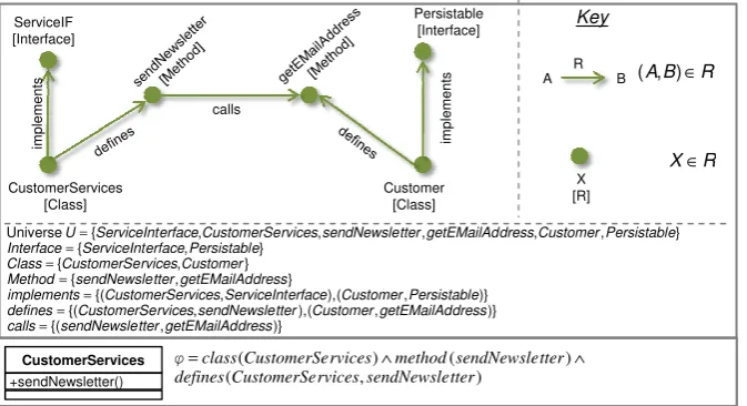
Figure 1: Representation of systems and models.
must be possibleto reflect the intensional characteristics of architectural models in that formal representation and to define and check architectural compliance.
2.1 Overview
The proposed approach is based upon a formalization asstructures[HR04]. Structures consist of a universe of atomic entities and a set of n-ary relations over that universe. Since this is a rather universal definition, also software systems can be represented by structures. Fig.1depicts a structure representing a software system cut-out. It consists of an entity CustomerService
that is an element of the unary relation Class with the meaning that CustomerService is a class. This class provides a method to send newsletters to customers, for this purpose it calls a getEMailAdressmethod on theCustomer class. The call relation between both methods is represented as a corresponding tuple of the binary relationcalls.
Thesignatureof a structure defines which relations are actually available. A signature is a set
of relation symbols that are mapped to relations by a concrete structure. The symbols defined in a signature can also be used in first-order logic formulae. These can contain predicates that relate to the relation symbols of the signature and can be evaluated over structures that have corresponding relations.
Translated to the issue of software system representation, this interrelationship could be used to represent models of software systems. A signature defines the symbols that can be used to describe arbitrary systems, for example the relation symbolsClasss, Interfaces, Methods,
implementss,definess, andcallss. A concrete system, like the system in the upper part of Fig.
1, is represented as a structure. The relation symbols are mapped to the specific relations of the structure, for example,Methodsis mapped toMethod. A cut-out of a signature for component-based systems will be introduced in Sec.2.2.
Architecture Model
Design Model
A
D
A
φ
φ
D) ( A
M φ M(φD)
Architecturally compliant?
) ( ~ )
( A ac M D
M φ φ
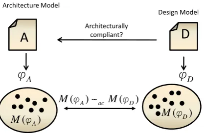
Figure 2: Formalization of architectural compliance.
model is satisfied by the structure representing the system. The lower part of Fig. 1shows a simple UML class diagram and the corresponding first-order logic expression that trivially states as a conjunction of predicates that the modelled class and its method have to be present in the software system. Sec.2.3will describe how statements are systematically derived from models. The approach introduced in [EHK06] applies the distinction of intensional and extensional statements to first-order logic formulae. An extensional statement, in contrast to intensional statements, is a statement whose set of satisfying structures is closed under adding entities and relation tuples, and removing entities that are not explicitly mentioned by the statement. For example, consider again the class diagram and its statement from Fig. 1. Further classes, in-terfaces, or methods could be added to the depicted structure without losing the property that it satisfiesϕ. The same for entities that are not referred to explicitly inϕ, for exampleCustomer.
Eden uses this classification to classify models of the architecture, design, and implementation level by the degree of abstraction they provide. Eden comes to the conclusion that architectural statements are in general intensional statements. For example, consider architectural layers that define an access hierarchy in a system. Of course, entities like components, can be added to the system in a way that the hierarchy is violated. Design models, on the other hand, as usually created in component-based software development describing specific system elements such as components and interfaces, internal structures and behaviour of components, are extensional models.
Whether a given design model D is compliant to a given architecture model A depends on the relationship between the sets of structures, M(ϕA) andM(ϕD), respectively, that satisfy the corresponding statementsϕAandϕD. The definition of that relationship, depicted as∼acin Fig.2, is affected by the fact that design models are extensional, as we will see in Sec.2.4.
2.2 Formal Representation of Component-based Systems
Part Connector rgPart connectorT rcPart connectorS rt ProvidedPo Connector rg connectorT rt RequiredPo Connector rc connectorS Interface rt RequiredPo rtType requiredPo Class rt ProvidedPo rtType providedPo rt RequiredPo Component rt requiredPo rt ProvidedPo Component rt providedPo U Connector U Part U rt RequiredPo rt ProvidedPo Port × ⊆ × ⊆ × ⊆ × ⊆ × ⊆ × ⊆ × ⊆ ⊆ ⊆ ⊆ ∪ = , , C1 r2:C3 r1:C2 J
px pj : Cl
py K )} , {( )} 2 , {( )} , {( )} " depicted not " , {( )} " depicted not " , ( ), , {( )} 2 , 1 ( ), 1 , 1 {( )} , 3 ( ), , 1 {( } { } , { } { }, 2 , 1 { } , , , 2 , 1 , , 3 , 2 , 1 { J Cl implements r con rcPart connectorS px con rc connectorS px rtType requiredPo py Cl pj rtType providedPo r C r C part py C pj C rt providedPo px rt RequiredPo py pj rt ProvidedPo con Connector r r Part py px pj r r J C C C U = = = = = = = = = = = = Example: Relations: C J p I q } , { )}, , {( )} , ( ), , ( ), , {( }, , { } { }, , { } , , , , { I J refersTo J C provides I q J p C p contains J I Interface C Component q p Package q p J I C U = = = = = = = Class Class inherits Interface Class implements Class Component es encapsulat Interface Interface refersTo subtypes Interface Component requires provides Interface Component Package contains Package Package subPackage U Class U Package U Interface U Component × ⊆ × ⊆ × ⊆ × ⊆ × ⊆ ∪ × ⊆ × ⊆ ⊆ ⊆ ⊆ ⊆ , , ) ( , , , Example: Relations:
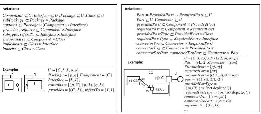
Figure 3: Cut-out of a signature for component-based systems and exemplary structures.
to UML models. The examples for the chosen formalization are simplified UML component diagrams. A more exhaustive description can be found in [Her10].
Fig.3depicts some of the relation symbols2reflecting component-based systems. The left part of Fig. 3 illustrates the interrelations between components, interfaces, and classes. The main first-class elements in component-based systems are components and interfaces. Components (entities that are in the relationComponent) provide functionality to the environment by pro-viding interfaces and describe what they need to realize that functionality by describing which interfaces are required. Both, components and interfaces, represent types that can be instanti-ated, and both are structured by packages which provide namespaces. Interfaces can refer to each other comparable to associations. Furthermore, interfaces can be specialized by subtyping. Classes (in the object-oriented sense) are component-local types and can only be used there. As a consequence, inheritance hierarchies are also encapsulated by components. Classes can imple-ment interfaces provided by the surrounding component. As an example of type formalization, consider the left example in Fig. 3. The package structure is formalized by the unary relation
Package, the contained elements by the binary relation symbolcontainsbetween packages and
the union of interfaces and components. The set of interfaces and components are represented by unary relations, too. The provides relation contains a single element to reflect thatJrefers to I.
The right part of Fig.3 shows relation symbols required for the specification of the internal structure of components. The environment interacts with an instance of a component via ports.
ProvidedPortsare similar to reference variables that are accessible from outside the component
to interact with it. ProvidedPortsare typed with a class of the component but to the outside it appears as an instance of the interface(s) that this class implements. A required port is like a reference variable that can be used inside of the component (i.e. the definition of classes). Required ports are typed by interfaces. To specify the inner structure of components, parts and
2Note that relation symbols in the upper part of the figure and relations in the examples mapped to the symbols are
AllowedDependency
-level : int -pkgName : String
Layer
src.level > trg.level -trg
1 0..*
0..* -src 1
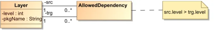
Figure 4: A simple meta model for layers.
connectors are used. Parts are typed and named elements of which an instance of a component is composed.
2.3 Formal Representation of Models of Systems
The first-order logics statementϕM representing a model Mis a formula over a signature that contains the relation symbols defined in the signature for component-based systems. As we will see, a statement can refer to additional symbols.ϕMis a conjunction of formulae that are defined for the single elements of a model. For example, consider Fig.1. The elements of the conjunction result from the single model elements. i.e. the class, the method, and the fact that the depicted class defines the depicted method.
Thus, the shape of the statements of model elements can be defined template-like for single meta model elements. In the example above, such a definition would state that for a methodmin general, a formula Method(m)∧de f ines(c,m) is created whereas the variablemis replaced by the unique identifier of the method andcis replaced by the unique identifier representing the class definingm. Furthermore, we distinguish between the definition of extensional and intensional formulae for meta model elements. The following sections describe the mapping between two different meta models and the formal representation as first-order logics statement.
2.3.1 UML Design Models
The mapping is defined for UML Component and Composite Structure Diagrams and is rather straightforward. Since they are interpreted as design models for component-based systems, the statements representing them are extensional. For example, components of UML are mapped to statements simply stating that a corresponding entity ewithe∈Component has to be present. The same holds for other UML language elements like interfaces, parts, connector, etc., and relationships among them.
2.3.2 Models of Architectural Layers
Fig.4depicts a simple meta model to model the layer of a system. It consists of layers that can be explicitly connected by “AllowedDependency” relationships to indicate that a layer is allowed to access another. Of course, the hierarchy of the layers must be adhered to. The attribute “pkgName” refers to the name of a package (see Sec.2.2) that the layer is mapped to.
The following extensional statements are created for instances of this meta model:
• For each instanceaof “AllowedDependency”: AllowedDependency(l,m) whereasl repre-sents the layer pointed to bya.srcandmthe layer pointed to bya.trg.
Intensional statements are created for layers only, expressing that components in a layer can only access components of different layers if there exists a corresponding allowed dependency relation. Thus, for every layerlis defined:
¬∃m:Layer(m)∧ ¬allowedDependency(l,m)∧dependency(l,m)
The definition of dependency uses the pkgName predicate to map the dependencies between layers to dependencies between packages, and finally, to single elements inside the packages (see [Her10]). For example, a dependency between two layers exists if they are mapped to two packages, the first containing a component that provides or requires an interface defined in the second. This, and other forms of dependencies, are defined asdependi(e,f) predicates, such as
depend1(e,f)BComponent(e)∧Inter f ace(f)∧(provides(e,f)∨requires(e,f))
2.4 Architectural Compliance of Design Models
To check whether a design model is compliant to an architecture model, one could assume that is has to hold that every structure satisfying the statement of the design model also satisfies the architecture model. In general, this will never be the case, since the design model is extensional, and a given satisfying structure can be extended and will still satisfy the design model. Thus, extending a structure satisfying both the intensional architectural model and the extensional de-sign model, can result in structure violating the architecture although being correct regarding the design.
Hence, we only take theminimal satisfying structuresinto account for the definition of com-pliance. A minimal structure of ϕ cannot be further reduced without losing the property of satisfyingϕ. In case of extensional statements, the set of minimal structures is finite REF. Ifϕ is simply a conjunction of predicates, like statements of UML design models (see Sec. 2.3.1), there is a unique minimal structure. Thus, we can informally define for∼ac from Sec. 2 that
M(ϕA)∼ac M(ϕD) if and only if every minimal structure mfrom M(ϕD) is also an element of
M(ϕA).3
Intuitively, this definition distinguishes compliance fromrefinement, which cannot be ensured between architecture and design. Refinement implied that every satisfying structure for the de-sign would also satisfy also the architecture. Hence, the system exactly satisfying the dede-sign as well as system that conform to the design but which are underspecified by it had to conform to the architecture — this cannot be ensures in general due to the intensional characteristics of the architecture. For this reason, the definition of compliance does not take systems into account that are underspecified by the design but only the system represented by the minimal structure.
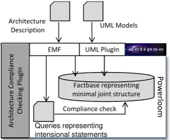
2.5 Prototype Tool Concept
The approach was evaluated by a tool prototype developed as Eclipse plugin (see Fig.5). It uses the logic programming system Powerloom [Inf] to represent structures as factbases and
3More precisely: mcan be extended by tuples of relations that are specific to architecture meta model only, like
A
rc
h
it
e
ct
u
re
C
o
m
p
li
a
n
ce
C
h
e
ck
in
g
P
lu
g
In P
o
w
e
rlo
o
m
Architecture Description
UML PlugIn EMF
Compliance check UML Models
Factbase representing minimal joint structure
Queries representing intensional statements
Figure 5: Structure of the prototypical tool.
first-order logics statements as queries. Instances of arbitrary architecture meta models, such as the simple layers meta model in Sec.2.3.2, are read in as Ecore files with help of the Eclipse
Modeling Framework (EMF) [SBPM09].
From the architecture model and the UML design model, a factbase is generated representing the unique joint structure satisfying the extensional parts of the models. The intensional state-ments for the elestate-ments of the architecture model are annotated in the meta model as Powerloom queries. The model-specific queries (see Sec. 2.4) are generated from these annotation and are evaluated by Powerloom and return violations of the intensional constraints of the architecture model.
3
Case Study – Checking Architectural Layers
The approach and the prototype were applied in an industrial cooperation project as part of a pro-cess for quality assurance. The industrial partner had planned to introduce a new medium-sized information system (about 130,000 lines of Java code, 1,600 classes and interfaces). Architec-tural compliance checks should be executed to investigate whether the design was still compliant to the intended logical reference architecture. Given were an informal description of the intended architecture, which was formalized as a model according to the meta model for layers introduced in Sec. 2.3.2, and a static UML model for the design. Technically, both models are loaded into the tool as Ecore files and a proprietary annotation file describing which intensional queries have to be generated for meta model element instances4. Each layer was mapped to a package from the design model by setting the package name attribute.
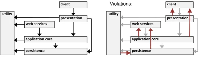
The considered system is subdivided into different layers (see Fig.6). Like a usual information system, it consists of a layer containing the application logic (application core), a layer handling the data access (persistence), and layers providing functionality for user interaction (presentation and client) or interaction with external applications (web services).
The persistence layer and its outgoing dependencies, for example, are transformed into the
4Since the UML design model is extensional, such annotations were defined for the sample architecture meta model
client
utility
presentation web services
application core
persistence
client
utility
presentation web services
application core
persistence Violations:
Figure 6: Case Study Layers Structure and Detected Violations
following facts:
Layer(persistence), level(persistence,1),
pkgName(persistence, org.x.persistence), AllowedDependency(persistence,utility)
According to the definition of the intensional statements for layers, the statement for the per-sistence layer is
(not (exists ($m)(and (Layer $m)
(not (allowedDependency persistence $m)) (dependency persistence $m)))
which is a version of the intensional statement for layers as presented in Sec.2.3.2interpretable by Powerloom.
The right part of Fig.6depicts the identified violations. Most of the violations between the presentation layer and the client result from using objects for the transportation of data between these layers by data transfer objects [Fow02]. These objects were defined inside the client and were used by the presentation layer. The violations between application core and client appear due to a kind of searching functionality that was implemented in the client layer which was simply not the intended place. The utility layer contains security functionality which accesses the persistence layer for identification purposes and therefore produces violations. Some violations (between application core and web services) are caused by imports which are used to realize callbacks, as needed for the observer pattern.
4
Related Work
This work is strongly influenced by the theoretical framework of Eden, Hirshfeld, and Kazman as mentioned in Sec.2.1. They mainly deal with the general categorization of design descriptions and the application to design patterns. The issue of compliance between two or more models is not tackled.
There exist tools and approaches in the field of architectural conformance checking.
Depen-dency Structure Matrices (DSM)capture the dependencies between modules of system[Ste81].
weighted as numerical value. Tools likeLattix LDM allow software architects to define con-straints like “can-use” to restrict the value certain entries are allowed to have [SJSJ05]. Since architectural rules are more general than those dependency constraints, DSM provide only lim-ited flexibility. Moreover, most approaches support only a limlim-ited set of design artefacts to be checked; furthermore, the integration of a high-level architecture description is not possible nor is such a description provided by tools themselves.
Reflexion modelsare another technique to check architectural compliance [MNS01]. The
ar-chitect generated a high-level model manually, containing arar-chitectural modules and dependen-cies between them “as intended”. A source code model is generated automatically, reflecting the same dependencies between source code elements “as they are”. A manual mapping between architectural elements and source code elements allows it to compare the overall structures and to depict differences in the set of relationships as so-called reflexion models. Implementations of this kind of compliance checking are for example [KLMN06,DHHJ10,RVP06]. Although they provide high-level models of the software architecture, and can hence potentially be better inte-grated into model-driven engineering, they reduce architectural rules to dependency constraints as well, and often support only few artefact types, i.e. meta models.
Most flexible w.r.t different architectural rules are query-language based approaches like CQL, .QL, or JQuery which are query-language for object-oriented source code [CQL, MVH+07,
Vol06]. Based on first-order logics they provide the most expressive mechanism to define ar-chitectural rules. Most tools, however, only support a small set of source code but not design models to be checked, and do not provide a high-level architecture model.
More related work regarding architectural compliance checking can be found in the field of consistency management for models, an overview for UML models can be found in [EB04]. However, examples mostly do not deal with the consistency or views on the same or a simi-lar level of abstraction, and not with consistency towards an intensional model. There are also approaches that deal specifically with the consistency of architecture and design models. For example, [SB05] deals with checking architectural features in component diagrams by using de-scription logics. Egyed, for example, outlines an approach in [Egy00] for consistency checking between C2 ADL architecture descriptions and refining UML high-level designs. For this ap-proach holds the same limitation as for other Architecture Description Languages: they do not provide description techniques with intensional character.
5
Conclusion
The contribution of this work is to provide an approach for checking architectural compliance of different kind of artifacts that are created in the development of component-based systems. This approach provides a solid formal foundation for a broad range of constraints that a software architecture may impose on design models of different meta models and, thus, can improve the situation of current tool support.
dif-ferent meta models. Furthermore, we would like to evaluate the flexibility and usability of this approach in more industrial case studies with regard to the definition of different architectural constraints.
Bibliography
[BBS03] M. Bennicke, W. Bischofberger, F. Simon. Eclipse auf dem Pr¨ufstand: Eine Fallstudie zur statischen Programmanalyse.OBJEKTspektrum05:22–28, 2003.
[BCK05] L. Bass, P. Clements, R. Kazman.Software architecture in practice. Addison-Wesley, 2005.
[BMR+96] F. Buschmann, R. Meunier, H. Rohnert, P. Sommerlad, M. Stal.Pattern-Oriented
Software Architecture, Volume 1: A System of Patterns. Wiley, Chichester, UK, 1996.
[CQL] Code Query Language specification. http://www.ndepend.com/CQL.htm.
http://www.ndepend.com/CQL.htm
[DHHJ10] F. Deissenboeck, L. Heinemann, B. Hummel, E. Juergens. Flexible Architecture Conformance Assessment with ConQAT. InProc. of the 32nd International
Confer-ence on Software Engineering (ICSE 2010). ICSE ’10, p. 247–250. ACM, New York,
USA, 2010.
[EB04] M. Elaasar, L. C. C. Briand. An Overview of UML Consistency Management. Technical report, Department of Systems and Computer Engineering, Carleton University, 2004.
[Egy00] A. Egyed. Validating Consistency between Architecture and Design Descriptions. In
Proc. of 1st Workshop on Evaluating Software Architecture Solutions. 2000.
[EHK06] A. H. Eden, Y. Hirshfeld, R. Kazman. Abstraction classes in software design. IEE
Software153:163–182, 2006.
[Fow02] M. Fowler. Patterns of Enterprise Application Architecture. Addison-Wesley Long-man, 2002.
[Her10] S. Herold. Checking architectural compliance in component-based systems. In SAC
’10: Proceedings of the 2010 ACM Symposium on Applied Computing. Pp. 2244–2251.
ACM, New York, USA, 2010.
[HR04] M. Huth, M. Ryan.Logic in Computer Science: Modelling and Reasoning about Sys-tems. Cambridge University Press, New York, USA, 2004.
[IEE00] IEEE. IEEE Recommended practice for architectural description of software-intensive systems. Technical report, 2000.
[Inf] Information Science Institute, University of Southern California. Powerloom Knowl-edge Representation and Reasoning System.
[KLMN06] J. Knodel, M. Lindvall, D. Muthig, M. Naab. Static Evaluation of Software Archi-tectures. In Proceedings of the 10th European Conference on Software Maintenance
and Reengineering 2006 (CSMR 2006).Pp. 285–294. Mar. 2006.
[MNS01] G. C. Murphy, D. Notkin, K. J. Sullivan. Software reflexion models: bridging the gap between design and implementation.IEEE Transactions on Software Engineering 27(4):364 –380, Apr. 2001.
[MT00] N. Medvidovic, R. N. Taylor. A Classification and Comparison Framework for Software Architecture Description Languages.IEEE Trans. Softw. Eng.26(1):70–93, 2000.
[MVH+07] O. de Moor, M. Verbaere, E. Hajiyev, P. Avgustinov, T. Ekman, N. Ongkingco, D. Sereni, J. Tibble. Keynote Address: .QL for Source Code Analysis. InProc. of the 7th IEEE International Working Conference on Source Code Analysis and Manipula-tion. P. 3–16. IEEE Computer Society, Washington, USA, 2007.
[Obj10] Object Management Group. UML Superstructure Specification Version 2.3. 2010.
[RRPM08] A. Rausch, R. Reussner, F. Plasil, R. Mirandola (eds.). The Common Component
Modeling Example: Comparing Software Component Models. Lecture Notes in
Com-puter Science 5153. Springer, 2008.
[RVP06] A. Raza, G. Vogel, E. Pl¨odereder. Bauhaus — A Tool Suite for Program Analysis and Reverse Engineering. In Ada-Europe. Lecture Notes in Computer Science 4006, p. 71–82. Springer, 2006.
[SB05] J. Simmonds, M. C. Bastarrica. Description Logics for Consistency Checking of Archi-tectural Features in UML 2.0 Models. 2005.
[SBPM09] D. Steinberg, F. Budinsky, M. Paternostro, E. Merks.EMF Eclipse Modling Frame-work. Addison-Wesley, 2009.
[SJSJ05] N. Sangal, E. Jordan, V. Sinha, D. Jackson. Using Dependency Models to Manage
Complex Software Architecture. In Proceedings of the 20th annual ACM SIGPLAN
OOPSLA conference. P. 167–176. ACM, New York, USA, 2005.
[Ste81] D. V. Steward. The design structure system: a method for managing the design of com-plex systems.IEEE Transactions on Software Engineering28(3), 1981.
[SVC06] T. Stahl, M. Voelter, K. Czarnecki.Model-Driven Software Development: Technology,
Engineering, Management. John Wiley & Sons, 2006.