Saturation of front propagation in a reaction diffusion process describing plasma damage
in porous low-
k
materials
Soghra Safaverdi,1Gerard T. Barkema,2,3Eddy Kunnen,4Adam M. Urbanowicz,5and Christian Maes1 1Instituut voor Theoretische Fysica, K.U. Leuven, Belgium
2Theoretical Physics, Utrecht, The Netherlands
3Instituut-Lorentz for Theoretical Physics, Leiden University, The Netherlands 4imec, Kapeldreef 75, B-3001 Heverlee, Belgium
5Semiconductor Physics Section, Department of Physics and Astronomy, K.U. Leuven, Belgium
(Received 14 February 2011; revised manuscript received 18 April 2011; published 28 June 2011) We propose a three-component reaction-diffusion system yielding an asymptotic logarithmic time dependence for a moving interface. This is naturally related to a Stefan problem for which both one-sided Dirichlet-type and von Neumann-type boundary conditions are considered. We integrate the dependence of the interface motion on diffusion and reaction parameters and we observe a change from transport behavior and interface motion∼t1/2to logarithmic behavior∼lntas a function of time. We apply our theoretical findings to the propagation of carbon depletion in porous dielectrics exposed to a low temperature plasma. This diffusion saturation is reached after about one minute in typical experimental situations of plasma damage in microelectronic fabrication. We predict the general dependencies on porosity and reaction rates.
DOI:10.1103/PhysRevB.83.245320 PACS number(s): 05.60.−k, 05.20.Dd, 66.30.H−
I. INTRODUCTION
The generation and propagation of interfaces in reaction-diffusion systems is of great importance in a variety of scientific and technological contexts. In nature, the interface often spatially separates two macroscopically different homo-geneous regimes in which one phase or product dominates another one. Typically, at least one particle type diffuses through the medium while reacting with other particles. Births and deaths depend on the spatial location and on the presence of other particle types. Then, when installing appropriate initial and boundary conditions one often sees the appearance of an interface and one asks for the typical temporal behavior in its initial growth and further propagation. The case we treat here is boundary driven from one side, with symmetric bulk diffusion for one particle type that invades the region of a second particle type, while constantly being annihilated by yet a third type of particle. That creates a moving phase boundary and thus goes under the general name of the Stefan problem.1,2
The present work is inspired by experimental investigations on plasma damage in porous low-capacitive materials (low-k, see Ref. 3). One imagines here a porous SiOC material which is exposed via one of its physisorbedaries to radicals such as active oxygen atoms. These radicals diffuse through the material while removing hydrophobic carbon-hydrogen groups and while being chemi-adsorbed in the pores of the material. One then observes the appearance and motion of an interface separating a rich (pristine) carbon-phase from a damaged (oxygen-rich) layer. It is important here to understand the time dependence of that motion and its dependence on diffusion and reaction parameters, which can further be related to material and chemical properties. We come back to this application in the separate Sec.IV.
Of course, the literature on interface motion from reaction-diffusion equations is vast, and many different phenomena have been reported. In particular, damage spreading and related front propagation can take many different forms which we
cannot at all review here (see, e.g., Refs. 4–6 for general research aspects). As just one very famous example for one-dimensional front propagation, as we also have here, reaction-diffusion equations such as of the type of Kolmogorov-Petrovsky-Piskounov show interface motion between two homogeneous phases at constant speed.7 That then takes the form of traveling waves in which one phase advances over the other phase. Here, however, the proposed model shows the motion of the interfacex(t)ln(1+at+b√t) (in one dimension as a function of timet) to be logarithmic, which means that after an initial period diffusion saturation occurs. The main point is that the diffusive motion is boundary driven and that the propagation is limited by the reactions. For the purpose of the application, the logarithmic behavior is caused by the disappearance of the oxygen radicals before reaching the moving interface separating them for the carbon-rich environment. The√t within the logarithm, mostly visible in an initial time period, originates directly from the diffusive motion.
The next section contains the specific mathematical model in the form of coupled partial differential equations. They give a mean-field description of the reaction-diffusion system. The main finding is the change from a diffusive to a specific logarithmic time dependence for the interfacex(t) as above, with the study of dependencies on initial conditions and dynamical parameters. We give a physical heuristics for understanding the basic characteristics via a linearized model. SectionIIIon numerical results summarizes the behavior of our model as a function of the physical parameters. Our results agree with the analytical results of the linearized model, but the higher flexibility of simulations allow for obtaining additional information and predictions concerning the dependence on the various parameters in the model.
contains already the basic set of differential equations, but no systematic analysis was performed and the distinction between different (one-sided) boundary conditions was not considered. The present paper also adds the interesting connections with reaction-diffusion systems of the Stefan type.
II. MODEL AND MAIN FINDINGS
There are three types of particles. The first are called free O particles, which can diffuse but can also change into bound O particles and further annihilate with either bound O particles or with C particles
free O→α bound O, free O+ bound O→ ∅κ ,
free O+C→ ∅R ,
and no other reactions or diffusions take place. The letters are chosen in the context of the later application in Sec.IV
with O for oxygen and C for carbon. The word “free” will there be understood as “reactive” and “bound” will mean adsorbed to the inner surface, either physically or chemically. Once oxygen atoms are absorbed on the surface they start to move around until they recombine and desorb. In other words, since in the experimental conditions desorption of bounded oxygen molecules typically occurs through recombination, reversible desorption is not taken into account.9,10 For the moment we continue to use the more general words “free” and “bound,” as the mathematical setup can have different natural realizations.
The dynamics is further determined by the initial condition at time zero when there are only C particles with homogeneous density and by the boundary conditions. The physics we have in mind concerns a three-dimensional region of locations (x 0,y,z), which is isotropic over the (y,z) coordinates. For the boundary conditions at thex =0 plane we consider two possibilities. The first, of Dirichlet type, specifies a constant density of free O particles at x =0; the second, of von Neumann type, gives a constant flux of particles entering the region atx=0. For the questions and the problem at hand we restrict ourselves to an effective mean-field treatment, ignoring fluctuations or microscopic inhomogeneities, and the geometry is one-dimensional.
We consider the coordinate x 0 in which to express the profile of particle densities as a function of time t0. There are thus three types of concentrations ρ(x,t),c(x,t), and m(x,t), respectively, for free O particles, C particles, and bound O particles. The reaction-diffusion system is then defined via the equations
˙
ρ =Dρ−κρm−Rcρ−αρ,
˙
c= −Rcρ, (1)
˙
m= −κρm+αρ,
where the dotted left-hand sides are time derivatives. The concentrationρ (of the free O particles) undergoes a second spatial derivative in the right-hand side of the first line of Eq. (1); the parameter D >0 being the diffusion constant. The other parametersκ,R, andαare positive reaction rates.
The initial condition (t =0) specifies
c(x,t=0)=1, ρ(x,t=0)=m(x,t=0)≡0, for x >0,
(2)
meaning that we start with C particles fully occupying the material. On the other hand, the boundary conditions (x =0) can be taken either
Dirichlet type:ρ(x=0,t)=V ,
or von Neumann type:ρ(x =0,t)= −J, (3)
where we can take V =1 without loss of generality; the
J >0 stands for the rate of free O particles entering the region, which for the moment we leave as a parameter. It seems more natural to opt for von-Neumann-type boundary conditions for the specific application we have in mind, but we checked that after a transient time there is really no difference between Dirichlet and von Neumann conditions. In the case of von-Neumann-type boundary conditions, the valueρ(x =0,t) converges from being zero at time zero to a fixed finite value (equal to some V >0 depending on J) exponentially fast as time evolves. As a consequence, we mostly concentrate on just one type, that of Dirichlet boundary conditions with
ρ(x=0,t)=1 for all times, but further discussion on possible differences will follow below.
The results of numerical integration of the differential equations (1) are detailed in Sec. III. Our main finding is that the concentrationc(x,t) of C-particles (defining the absence of damage in the application of Sec. IV) shows an interface x(t) separating a C-poor from a C-rich phase. There area prioria number of different possible mathematical definitions of the position of the interfacex(t). A first one is to solvec(x(t),t)1/2 (or some other number) forx(t), which certainly makes sense when the interface is sharp enough, after some transient time, but is less useful for very small times. A second definition uses the same conditions as above, but we add the equation ˙x(t)= −D ρ[x(t),t] for the interface speed. That brings the problem in the natural neighborhood of Stefan problems,1,2also valid for very small times but more involved numerically. Whatever (reasonable) definition we take for
x(t) we invariably find that the motion is logarithmic of the general formx(t)=Aln(1+at+b√t) in a typical range of parameters for diffusion and reaction ratesD,κ,R, andα. The coefficientsA,a, andb depend on these parameters, see also in Sec.III. For small times the motion is diffusivex(t)∼√t
while it saturates asx(t)∼lntfor large timest. The transition between the two regimes is basically determined by the amount of reactivity, the more the O particles can be annihilated, the faster saturation sets in.
An approximate treatment toward the second Stefan-like definition of the interface motion described above can already be made visible for a much simpler linear system to which we turn next. We simplify Eq. (1) to a one-component reaction-diffusion equation by imagining an autonomous linear dynamics forρof the form
˙
ρ(x,t)=Dρ−βρ. (4)
makes sense in the damaged region [0< x < x(t)] where the carbon was depleted. The right boundary denoted byin what follows therefore plays the role of interface. We also can think ofβas a measure of reactivity and interaction, whileD
measures the diffusion. The main advantage is, of course, that now Eq. (4) can be solved exactly with boundary conditions
ρ(x =0,t)=1,ρ(x=,t)=0 and initiallyρ(x,t =0)=0. The solution is
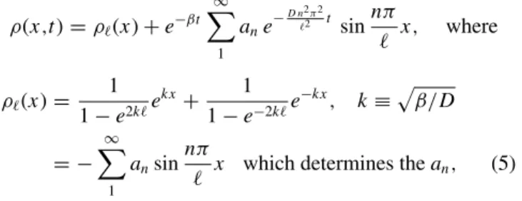
ρ(x,t)=ρ(x)+e−βt ∞
1
ane−
D n2π2
2 t sinnπ
x, where
ρ(x)= 1 1−e2ke
kx+ 1
1−e−2ke
−kx, k≡β/D
= −
∞
1
ansin
nπ
x which determines thean, (5)
andρ is the stationary solution on [0,]. In fact we see that
ρ(x,t) converges exponentially fast to ρ with rate β >0 uniformly in . We can already learn a great deal from the behavior at the edgex =. It is easy to find that
ρ()= −k
sinhk. (6)
We think now ofas the positionxof the interface and−ρ() is then the speed of the interface, so that Stefan’s condition
˙
x(t)=D k/sinh[kx(t)] can be integrated to give
x(t)=
D
β ln[1+βt+
2βt+β2t2]. (7)
We clearly recognize the behaviorx(t)∝√D/β lntfor large times t resulting in a straight line in Fig.1 and intersecting the vertical axis (smallt) at√D/β ln(2β). For small timest
Eq. (7) givesx(t)∝√tandx(t=1)√2Dfor smallβ >0. We can thus find the effectiveD andβ for Eq. (4) from the intersections of thex(t) as a function of lnt with the vertical axis, as in Fig.1, which provide consistency checks for our modeling equations.
0 5 10 15 20 25 30
1 10 100 1000 10000 100000 1e+06
x(t)
t
FIG. 1. Position of the interfacex(t) as a function of time. For longer times, the curve approaches a straight line, indicating that asymptoticallyx(t)=Aln(1+at).
Similarly, we can also solve Eq. (4) with von-Neumann-type boundary condition ρ(x =0,t)= −J but still putting
ρ(x=,t)=0 and initiallyρ(x,t =0)=0. The solution is
ρ(x,t)=ρs(x)+e−βt ∞
1
bne−
D(n−1/2)2π2
2 tcos(n−1/2)π
x,
where
ρs(x)=
J k
e−kx 1+e−2k −
ekx 1+e2k
, (8)
k≡β/D= −
∞
1
bncos
(n−1/2)π
x
which determines thebn.
Exponentially fast in time t, ρ(0,t)=J /k+O(e−k), and
hence we find that forJ ∼
β
D the von Neumann condition imitates the Dirichlet condition with fixed ρ(0,t)=1 and
ρ(x)ρs(x)exp−kx for large , at least for β=0. Clearly then, when the rate β would go to zero, some differences between Dirichlet and von Neumann (one-sided) boundary conditions can be expected, as we indeed recover in Sec.III Bfor the real model. The next section goes back to the full nonlinear model equations (1), but we will find the many general features to be similar to our chosen approximation above.
III. NUMERICAL RESULTS
We now turn to the full set of Eq. (1), and switch to computer simulations. First, we study the system for a specific set of parametersD=1.0, κ=0.1,R=1.0, andα=0.1, and apply Dirichlet boundary conditions; the primary motivation for this specific choice of the parameters lies in their numerical convenience. We apply a forward Euler integration scheme to Eq. (1) with a time step of t =0.001, and store the density profiles of C particles, free and bound O particles at timest =1,2, . . .. Based on our analytic solution (7) of the simplified description (4), we expect that for long times the interface positionx(t), defined as the (linearly interpolated) location where the C-particle density equals 1/2, changes in time asx(t)≈Aln(1+at), for some values of Aanda
which are determined by the system parametersD,κ,R, andα. Figure 1 shows that this expected long time behavior is confirmed by the simulation data.
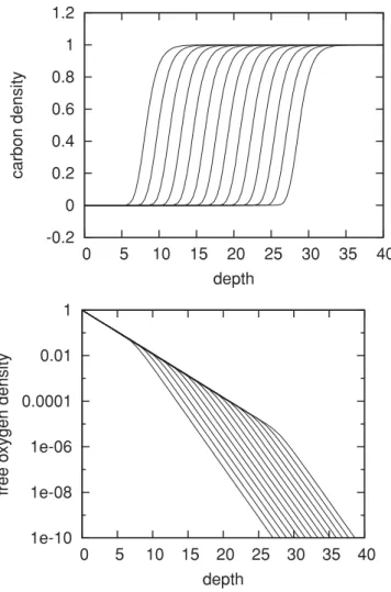
In the same simulations, we also determined the concen-trations of C particles and free O particles as a function of position, for the timest /100=1,2,4,8, . . . ,8192. These are
c(x,t), respectively,ρ(x,t) in Eq. (1). The resulting profiles of C concentration are shown in Fig.2(a). The C-density profile attains a sigmoid-like shape, which gradually moves deeper into the material. As the times of the curves are separated by a factor of 2, and the depth increases with the logarithm of time, the curves are more or less equidistant.
-0.2 0 0.2 0.4 0.6 0.8 1 1.2
0 5 10 15 20 25 30 35 40
carbon density
depth
1e-10 1e-08 1e-06 0.0001 0.01 1
0 5 10 15 20 25 30 35 40
free o
x
ygen density
depth
FIG. 2. Profile of the C concentration (top panel) and free O concentration (lower panel) as a function of depth, at timest /100= 1,2,4, . . . ,8192. Note that the top panel has a linear vertical scale, while the lower panel has a logarithmic vertical scale.
becomes constant even though we applied Dirichlet boundary conditions. This confirms our earlier analytic observation that the behavior for Dirichlet and von Neumann conditions soon becomes indistinguishable.
A. Influence of diffusion
An important ingredient is to understand the influence of the diffusion constantDon the temporal behavior of the interface. After all, the porosity and the architecture of the material can modify exactly that diffusive behavior.
We repeated the simulations with different values for the diffusion coefficient:D=0.5,1,2, and 4. Figure3shows the rescaled interface positionx(t)/√D, indicating that the main effect of variations inDis a rescaled amplitude:A∼√D, as expected from the linear model in Eq. (7). It appears therefore that we understand the influence of the connectivity of the porous material on the time dependence of the interface.
B. Influence of reactivities
The adsorption of the free O-particles and the chemical annihilation of the free O-particles with the bound O-particles
0 2 4 6 8 10 12 14 16 18 20
1 10 100 1000 10000
x(t)/sqr
t(D)
t
FIG. 3. Rescaled position of the interfacex(t)/√Das a function of time, for simulations in whichD=0.5,1,2, and 4. For longer times, the curves fall on top of each other, indicating that asymptoti-callyA∝√D.
(e.g. to create aO2 molecule which is chemically neutral for C-particles) and with the C-particles is the reactive content of our model. Obviously the C particles must remain to define an interface at all, but we can imagine lowering very much the adsorption of the free O particles. In the extreme case we exclude the adsorption of free O particles by settingα=0. Then, we have m(x,t)=0 always and everywhere which simplifies Eq. (1) somewhat. In the case of Dirichlet-type boundary condition ρ(x =0,t)=1, we basically have the transport of O particles through a layer of size x(t) with the difference in concentration fixed (and equal to 1): we thus expect from Fick’s law that the current ˙x(t)∼1/x(t) is proportional to the concentration gradient which gives us
x(t)∼√t. We have checked that this behavior is indeed found for very small adsorption rates, α=0 andκ =0. Figure 4
shows the numerical evidence.
On the other hand, with von Neumann boundary condition
ρ(x =0,t)= −J and for very small absorption ratesα=0
1 10 100 1000
1 10 100 1000 10000 100000
x(t)
t Dirichlet von Neumann sqrt (x) sqrt (x*log(x))
and κ =0, there is a continuous influx of free O particles leading to a concentration of them at the surface which increases in a power law fashion. That can be understood from the following calculation. Let us takeJ =1 and consider the function
ρ1(x,t)≡√t e−x/√t,
satisfying indeed ∂tρ1(x=0,t)= −1. Then, ∂tρ1(x,t)=
ρ1(x,t)/t[1+x/√4t] and∂2
xρ1(x,t)=ρ1(x,t)/t, so thatρ1 appears as a solution of the diffusion equation forx √t. We thus conclude thatρ1(0,t) grows as
√
t. Numerically, we find that the lack of saturation of free O concentration at the exposed surface does not alter the asymptotic behavior of the interface, but it does lead to a logarithmic correction. The behavior is consistent with x(t)∼√tlnt. Also for von Neumann boundary conditions, numerical evidence is presented in Fig.4.
IV. APPLICATION
Low dielectric constant (low-k) materials are typically used in semiconductor manufacturing to compensate for theRC
delay and power consumption increase in microelectronic devices associated with their continuing scaling-down.3,11The microelectronics community has adoptedkas a representation of the relative permittivity or dielectric constant in contrast to the scientific communities usingεr. Nowadays, porous low-k dielectrics based on silica and silsesquioxanes with 10–15% of organic hydrophobic groups are the most favored class of materials for advanced interconnect technology nodes.11 The hydrophobic groups are bonded to a Si atom in the SiO4/2 matrix and can be represented as O3≡SiCHx. To reach ak value below 3.0, introduction of artificial porosity is needed (the k value of air is close to 1).3 Advanced low-k materials have a porosity of 25–50% and a typical pore size being close to 2–2.5 nm. Although the matrix of these materials has properties similar to traditional SiO2, their chemical stability and reactivity strongly depend on porosity. Materials with interconnected pores are chemically active because of the high diffusion rate of active chemicals. In particular, the surface diffusion of adsorbed radicals is much faster than the desorption, which is our motivation not to include reversible adsorption-desorption in our model equations (1), see Refs.12 and13for specific experimental estimates.
During device fabrication, the porous low-k dielectrics are exposed to various plasmas that might degrade their properties. The most challenging plasma treatment is related to plasmas based on oxygen- or hydrogen-containing chemistries that are used to remove organic photoresist masks used for pattern transfer from the low-k films.14 The challenge arises from the similar chemical composition of the low-kfilm and the organic photoresist mask. Both materials contain C-H bonds. The plasma radicals that remove the organic mask also penetrate the porous low-kdielectric film destroying its Si-CH3 bonds. This leads to the formation of polar Si-OH groups as a result of direct chemical reaction with active radicals or saturation of≡Si•broken bonds by OH groups from ambient moisture. The Si-OH groups are centers for further moisture adsorption.15The absorbed moisture with ak value of 80 can fill the whole open pore volume of the material
significantly increasing its k value which is summarized as damage.
Two commonly known approaches are used for the pho-toresist mask removal: (i) a low temperature, low pressure anisotropic plasma, where the photoresist is removed by an ion-assisted process, oxidizing or reducing plasma chemistries at low temperatures10 and (ii) hydrogen-based downstream plasma (DSP) where the resist is removed at high temperatures by a thermally activated chemical process.16 According to recent publications,10,16 both approaches remove C from low-k materials. However, ion-assisted processes remove hydrophobic Si-CH3 groups and graphitized C (residual C that remains after film fabrication), while a thermally activated chemical process with hydrogen plasma removes only graphitized C from low-k dielectrics. In both cases the depth of C-carbon removal can be directly measured with spectroscopic ellipsometry.8,14 Various experimental results have shown the typical time dependence of the depth of C removal. In particular, the typical logarithmic time dependence was observed, as is the one we have derived in the present paper.
The depth of the plasma radical penetration in the low-k
pores determines the extent of plasma damage. Clearly then, the role of Knudsen diffusion is important and our analysis in Sec.III Aclarifies some aspects. For example, the extent of plasma damage can be a few times higher for mesoporous dielectrics with high porosity levels in comparison with nanoporous dielectric with low porosity levels.17,18
As a word of caution and limitations of our approach, plasma damage of low-kmaterials is a complex phenomenon that results in changes of their bonding structure and pore morphology.3 The complexity also increases due to the fact that porous low-kdielectrics are usually amorphous materials with a random pore structure.3 Our set of reaction-diffusion equations (1) can be generalized to include some of these aspects, but soon a more detailed simulation analysis becomes necessary.
V. CONCLUSION
The propagation of damage when a pristine material is exposed to diffusing and reacting particles saturates loga-rithmically. The initial position of the interface is diffusive
∼√t but soon saturates ∼lnt when reactions prohibit the propagation of the damage. The problem can be modeled as a reaction-diffusion system of coupled differential equations where the position of the interface can be determined by viewing it as a Stefan problem. We have discussed Dirichlet and von Neumann boundary conditions, solved a linear approximation, and we have found the detailed influence of re-activities and diffusivity. Numerical integration of the coupled reaction-diffusion equations is in full accord with experimental findings in the context of microelectronic fabrication of low-k
materials.
ACKNOWLEDGMENT
1J. Stefan, Annalen der Physik und Chemie42, 269 (1891). 2S. C. Gupta, The Classical Stefan Problem: Basic Concepts,
Modeling and Analysis(Elsevier, New York, 2003). 3K. Maexet al.,J. Appl. Phys.93, 8793 (2003).
4Bartosz A. Grzybowski,Chemistry in Motion: Reaction-Diffusion Systems for Micro- and Nanotechnology(John Wiley and Sons, New York, 2009).
5V. I. Dybkov,Reaction Diffusion and Solid State Chemical Kinetics, 2nd ed. (IPMS Publications, Kiev, Ukraine, 2010).
6Reaction-Diffusion Equations, edited by K. J. Brown and A. A. Lacey (Oxford University Press, Oxford, 1990).
7A. Kolmogorov, I. Petrovsky, and N. Piskounov, Moscou Univ. Bull. Math. A1, 1 (1937).
8E. Kunnen, G. T. Barkema, C. Maes, D. Shamiryan, A. Urbanowicz, H. Struyf, and M. R. Baklanov,Microelectron. Eng.88, 631 (2011).
9Y. C. Kim and M. Boudart,Langmuir7, 2999 (1991). 10E. Kunnenet al.,J. Vac. Sci. Technol. B28, 450 (2010).
11W. Volksen, D. M. Miller, and G. Dubois,Chem. Rev. 110, 56
(2010).
12P. Macko, P. Veis, and G. Cernogora,Plasma Sources Sci. Technol. 13, 251 (2004).
13J. Marschall and J. E. Boulter,J. Phys. D: Appl. Phys.39, 3849
(2006).
14A. M. Urbanowicz et al., Solid State Phenomena 134, 317
(2008).
15M. R. Baklanovet al., in Mat. Res. Soc., 2006.
16A. M. Urbanowiczet al.,Electrochem. Solid State Lett.12, H292
(2009).