2.1
Sewers
2.1.1 Pipe Material Selection Factors
The following considerations are the important factors to be considered before selecting or approving any pipe material and pipeline system for sewer networks:
a) Resistance to acidic condition of which is prevalent in sewer networks in tropical climates.
b) Resistance to sulphate attack from aggressive soils and groundwater. c) Resistance to corrosion in contaminated soils.
d) Resistance to severe abrasion from sewage flow and usual cleaning methods.
e) Resistance to groundwater entry (infiltration) and sewage escape (exfiltration) through joints.
f) Resistance of the joint material to corrosion and microbiological degradation.
g) Structural damages and other damages that may occur during handling.
h) Handling, laying and jointing care and difficulties.
i) Methods of pipe embedment to ensure good structural performance. j) Maintenance of structural strength and performance in service. k) Methods of maintenance and repair.
l) Cost of supply, transportation and installation.
m) Range and suitability of fittings for smaller diameter sewers. n) Previous local experience.
o) Local availability. p) Pipe pressure ratings.
q) The design life of a pipe shall be at least 50 years. r) All bolts and nuts shall be stainless steel (SS) 304.
s) Where necessary, special tools and trained personal shall be made available during the handling and installation of pipes.
Additionally, the following factors should be considered before selecting or approving any pipe manufacturer and supplier.
a) Compliance of products to standards.
b) Compliance to additional material and product requirements specified by the Commission.
c) Quality control and assurance practised by the manufacturer and supplier to ensure good pipe product quality from manufacturing to delivery.
2.1.2 Pipe Materials and Fittings
There is an extensive range of pipe materials available in Malaysia to be used as gravity, pressure and vacuum sewers. The materials and the standards which the pipes are required to conform to are as follows: a) Vitrified clay (VC) i) MS 672 ii) MS 1061 iii) BS EN 295 b) Reinforced concrete (RC) i) MS 881 ii) BS 5911 iii) BS 7874 iv) BS EN 681 v) BS EN 682 c) Ductile iron (DI)
i) BS EN 598 d) Mild Steel i) BS EN 10025 i) BS EN 10224 e) Stainless Steel i) BS EN 10220
f) Polyethylene (PE) solid wall i) MS 1058
ii) WIS 04-32-15 iii) WIS 04-32-14 iv) WIS 04-24-01
g) Unplasticised polyvinyl chloride (uPVC) solid wall i) MS 628 : Part 2 : Section 2
ii) MS 923 iii) MS 979
iv) AS/NZS 1477
h) Polyethylene profiled wall i) DIN 16961
i) Unplasticised polyvinyl chloride profiled wall i) AS/NZS 1260
j) Glass reinforced plastic (GRP) i) BS 5480
ii) AS 3571
k) Acrylonitrile butadiene styrene (ABS) i) AS/NZS 3518
Marking of all pipes shall comply with Malaysian or British Standards where applicable. Additional requirements to those given in the above standards may be specified from time to time by the Commission.
2.1.3 Pipe Selections
Except where otherwise specifically approved by the Commission, the pipe materials to be used for a specific type of sewer are listed below:
1) Gravity sewers
a) Rigid pipes b) Flexible pipes
i) VC i) GRP
ii) RC ii) Ductile Iron
iii) HDPE (Profile)
2) Force mains (Rising mains) i) Ductile Iron
ii) GRP iii) ABS
iv) HDPE (Solid) v) Steel
3) Vacuum sewers
i) ABS – for internal use
ii) HDPE (Solid) – for external use
There are specific requirements such as pipe class, joint type, linings etc. which the above approved pipe materials must meet in order to suit the above applications. Also, there are certain limitations for use of each pipe type. These requirements and limitations are specified in the following sections.
From time to time, the Commission will publish sewer selection guides which will provide more detailed direction on the selection and use of sewer materials.
For other pipe materials not listed above, their use will be given considerations in special circumstances. However, only pipes and fittings
from manufacturers and suppliers approved by the Commission are permitted to be used for sewerage applications.
2.1.4 Requirements and Limitations for Use of Certain Pipe
Material
Unless the exemption is granted by the Commission, the following limitations or requirements shall be followed when selecting the pipe materials:
I) Gravity Sewer
a) VC
i) Only size 150 mm or above shall be used.
ii) The minimum size for public sewer shall be at least 225 mm.
iii) Pipe shall not be used in unstable ground. iv) Flexible joints are recommended.
b) RC
i) Pipe protection linings are required.
ii) Only sizes 600 mm or above are allowed in compliance to the policy.
iii) Flexible joints are recommended. c) GRP
i) Pipe shall not be used in ground contaminated with high concentration of chemicals such as solvent that can degrade the pipe.
ii) Pipe shall not accept any industrial or other aggressive discharges that may affect the pipe integrity.
iii) Pipe shall be used only when no fittings are required. iv) Only sizes 600 mm or above are allowed.
d) DI
i) The use is only allowed for applications needed high pipe strength.
ii) Pipe protection linings and coatings are required.
iii) Polyethylene sleeving is required for all buried applications.
e) HDPE
i) Pipe shall not be used in ground contaminated with high concentration of chemicals such as solvent that can degrade the pipe.
ii) Pipe shall not accept any industrial or other aggressive discharges that may affect the pipe integrity.
iii) Only pipe with profile wall is permitted. II) Force Mains
a) DI
i) Pipe shall not be used in unstable ground.
ii) Pipe protection linings and coatings are required.
iii) Polyethylene sleeving is required for all buried applications.
iv) Flexible joints are recommended. b) GRP
i) Pipe shall not be used in ground contaminated with high concentration of chemicals such as solvent that can degrade the pipe.
ii) Pipe shall not accept any industrial or other aggressive discharges that may affect the pipe integrity.
iii) Fittings shall be made of ductile iron. iv) Only sizes 600 mm or above are allowed. c) ABS
i) Where VC or RC pipes are not suitable.
ii) Only for nominated projects or as permitted by the relevant authority.
d) HDPE
i) Pipe shall not be used in ground contaminated with high concentration of chemicals such as solvent that can degrade the pipe.
ii) Pipe shall not accept any industrial or other aggressive discharges that may affect the pipe integrity.
e) Steel
i) Pipe is allowed only for sizes 700 mm or above. ii) Pipe protection linings and coatings are required.
2.1.5 Vitrified Clay Pipe
Vitrified clay (VC) pipe is manufactured in Malaysia in diameters of 100 mm to 600 mm and lengths ranging from 0.91 m to 2.50 m. Larger
diameters of VC pipe are imported. VC pipes are classified according to the pipe ring crushing strength which depend on the manufacturing process and quality. VC pipes and fittings can be produced either unglazed or glazed on the interior and/or exterior. When glazed they need not be glazed on the jointing surfaces of the spigot and socket. VC pipes which are available in Malaysia are normally manufactured with spigot-socket flexible joints. Most manufacturers offer rubber ring seals. However, polyurethane seals are sometimes offered by some manufacturers. Vitrified clay pipe has extra chemical resistance that is suitable for sewerage applications. The VC pipe may be used even under very corrosive sewage environment. However, the potential for infiltration is great and must be minimised by careful laying procedures on site. Vitrified clay pipes are permitted for gravity sewers. The minimum permissible size for public gravity sewer shall not be less than 225 mm and for service connection shall not be less than 150 mm.
VC pipes and fittings shall conform to the requirements of MS1061. Pipe strength is classified by the crushing strength (FN) value tested in accordance with BS EN 295-3. The crushing strength for pipe with DN150 shall not be less than 22 kN/m. The crushing strength of the pipe with size ≥ DN 225 is classified by class number. All VC pipes and fittings shall be furnished with spigot-socket flexible joints and rubber ring seals or polyurethane seals. Glazing of VC pipes and fittings are preferred.
2.1.6 Reinforced Concrete Pipe
Reinforced concrete (RC) pipe is manufactured in Malaysia in diameters from 150 mm to 3600 mm. The standard pipe length is 3.05 m. RC pipe is classified according to pipe crushing test load or the three-edge bearing strength which varies with wall thickness and reinforcement. Common reinforced concrete pipes are not resistant to acidic corrosion which occurs in certain septic sewage conditions. The cement used to manufacture concrete pipe shall be factory produced by the cement manufacturer. Pipes can be manufactured using Portland Cement, Portland Blast Furnace Cement, Portland Pulverised Fuel Ash Cement and Sulphate Resisting Portland Cement. All these types of cements are corrosion resistance, except Ordinary Portland Cement and Rapid Hardening Portland Cement. To improve the corrosion resistance, high alumina cement mortar lining and sacrificial lining have been used. Low heat and super-sulphated cements have also been found in some tests to
improve the corrosion resistance. The inclusion of calcareous or limestone aggregate is another measure found to improve corrosion resistance. To resist corrosion by neutral sulphates occurring in aggressive soils and groundwater, RC pipes are sometimes manufactured using sulphate resistance cement and where not available, Portland Pulverised Fuel Ash Cement or Portland Blast Furnace Cement shall be used with the approval from relevant authority.
RC pipes are permitted for gravity sewers of diameter DN600 and larger. Pipe shall be of Standard Strength or higher as determined from structural design. RC pipes linings shall consist of either 12mm thick high alumina cement or 38 mm thick (as appropriate) sacrificial concrete lining. Other linings may be used if approval from the Commission is obtained. Concrete pipe junctions shall be fixed to the main pipe by the pipe manufacturer and fabricated to clay pipe dimensions. Flexible joints which utilise a rubber ring to join a rebated joint and a spigot to a socket are commonly used and are recommended. Ogee joint (fixed joint) shall be used in conjunction with concrete bedding haunching only. RC pipe when used for pipe jacking purpose, shall comply with BS 5911. The RC pipes also incorporate rebated joints with joint elastomeric ring seals either integrated in the unit or supplied separately.
2.1.7 Ductile Iron Pipe
Ductile Iron (DI) pipe manufactured in Malaysia for diameters from 80 mm to 1200 mm. The diameter imported pipe can be up to 2000 mm. Standard lengths are 6.0 m. DI pipe is classified according to wall thickness. The pressure rating of the pipe increases with an increase in wall thickness. Commonly used pipe strength is class K9 and shall comply with BS EN 598 for working pressure exceeding 6 bars.
DI pipe is permitted for force mains and internal pipings of pump stations. DI pipe shall be used for gravity sewers only where it is needed to take the advantages of the high strength of ductile iron, e.g. shallow cover sewers subjected to high live load or sewers of above ground applications.
Pipes shall have flexible joints, i.e. spigot-socket rubber seal joints or mechanical joints, except for pump station pipeworks and valve connections where flange joints shall be used.
Ductile iron will corrode when exposed to certain aggressive groundwaters and conveying certain aggressive water. Therefore, internal lining and external coating protection are required to protect against corrosions. Unless otherwise approved by the Commission, all ductile iron pipes shall
have an external coating to be determined by a Qualified Person based on actual soil condition. For internal lining of a constant full flowing pipe, ordinary Portland cement shall be used, while high alumina cement mortar or plastic adhesive lining is required for partly full flowing pipes. Buried pipe shall have zinc with bitumen external coating and fittings shall have bitumen external coating. The end surfaces shall include the internal surface of the socket and external surface of the spigot for flexible connection.
The finishing layer, which is normally bituminous product, shall cover the whole surface of the applied coating and shall prevent defects such as the loss of adhesion. In addition, the material of the finishing layer shall be compatible with the coating.
Unless otherwise approved by the Commission, all fittings and accessories shall be provided with external and internal epoxy coating.
Polyethylene sleeving shall be used for all the buried pipe and fittings.
2.1.8 Steel Pipe
Steel pipe is manufactured in Malaysia in a wide range of diameters up to 3000 mm and lengths up to 10 m. Pipe joints are normally welded utilising either spigot-socket ends, plain ends or a collar. Flanged and mechanical joints are also available.
Steel pipes will undergo corrosion when in contact with aggressive soil and sewage and, thus, require an internal lining and an external coating. Pipe internal linings normally include high alumina cement mortar, coal tar enamel, coal tar epoxy, sulphate resistant cement lining, or bitumen. Pipe external coatings often include coal tar enamel, bitumen enamel or asphalt enamel and glass fibre.
Steel pipes are permitted only for inverted siphons (depressed sewers) and internal pump station pipework. For force main larger than 700 mm, steel pipe may be used if the approval from the Commission is obtained.
The internal and external surfaces of the pipes and fittings shall be coated with thermosetting (epoxy paint or powder or epoxy tar resin) or thermoplastic (polyethylene or polyurethane) material. The type of external protection shall be determined by the Qualified Person based on soil condition. Following the completion of pipe jointing, exposed steel at the joints shall be protected from corrosion by manually applied external tape wrap and internal cement mortar lining.
A spigot and socket joint welded both externally and internally shall be used for pipe joints except for pump station pipeworks and valve connections where flange joints shall be used. Mechanical joints are only permitted for cut pipe lengths, where internal cement mortar lining at joints is not possible and where movement of the pipeline is to be allowed for.
2.1.9 Solid Wall PE Pipe
Polyethylene (PE) pipe is resistant to sulphuric acid of concentrations that might be found in septic sewage under the worst conditions.
PE solid wall pipe is available locally in diameters up to 1000 mm and in standard lengths of 6 m and 12 m. This pipe is normally butt fusion jointed. Pipe size of 160 mm or less may be flange jointed or electrofusion jointed. PE pipe is classified by pressure rating with static working pressures up to 1.6 MPa. High density PE (HDPE) is used for sewerage applications.
Since PE pipes are flexible, the design of the pipe/trench system is more critical than for rigid pipe materials. Compared to rigid pipes, the stability of flexible pipes relies more on the side support of the earth backfill around the pipe. Consequently, in an urban environment, where the side support may be removed during future adjacent construction of underground services, pipe failures could be more frequent. Ground conditions which provide poor pipe side support are unsuitable for flexible PE pipe.
Solid wall HDPE pipes are suitable for buried pressure sewer and buried vacuum sewer installations. Butt fusion joints shall be used for PE pipe. uPVC fittings are not permitted for force mains. Solid wall pipe for pressure main application shall be of minimum PE80-PN10. The use of specific strength shall depend on the depth and nature of the soil as confirmed by the Qualified Person. Solid wall pipes for vacuum sewer shall be minimum of PE80-PN8 and at least PN10 for heavy vehicle loading.
2.1.10 Profiled Wall PE Pipe
A profiled wall pipe is a pipe with a plain inside surface and with a ribbed or corrugated outside surface. The ribs or corrugations are normally either aligned circumferentially or helically. These corrugated or ribbed profiles optimise the pipe ring stiffness to weight ratio. The pipe can be designed with double-wall profile or triple-wall profile.
Corrugated high density PE pipe is available in Malaysia in a range of size from 100 mm to 3000 mm nominal diameter and in standard 6 m lengths. The standard joint is a flexible spigot-socket joint with rubber seal.
Pipes from specific manufacturers in this category may be permitted by the Commission to be used for gravity sewers where special circumstances require the benefits of such pipes.
2.1.11 Glass Reinforced Plastic Pipe
Glass reinforced plastic (GRP) pipe is currently required to be imported into Malaysia.
There are two principal manufacturing methods for GRP pipes, centrifugal casting and filament winding. The centrifugal casting GRP pipe incorporates silica sand in the wall structure in addition to resin and chopped strand mat glass fibres. The silica sand shall have a maximum particles size of 10 mm. The centrifugal casting GRP pipe shall be according to AS 3751.
The filament winding GRP pipe does not normally incorporate sand, which permits centrifugal casting GRP pipe to have a much thicker wall, and thus much higher ring stiffness than the filament winding GRP pipe. The filament winding GRP pipe uses continuous glass fibres wound helically about the pipe. The design of filament winding GRP pipe shall be in accordance with BS 5480.
Centrifugal casting GRP pipe is classified by internal pressure resistance for pressure applications and by pipe ring stiffness for non-pressure applications. Centrifugal casting GRP is available up to 10000 N/m2 stiffness and up to 2.5 MPa static working pressure. Filament winding GRP is available up to 5000 N/m2 stiffness and up to 1.6 MPa static working pressure
Centrifugal casting GRP pipe is available in sizes from 200 mm to 2400 mm and standard length of 6 m. The inner surface of the pipe is usually finished with a resin rich lining which is resistance to attack by sulphuric acid that may result from septic sewage. Centrifugal casting GRP pipe has a rubber sealing sleeve joint which is supplied fitted to one end. So jointing is similar to a spigot-socket joint. These pipes can also be supplied with flange joints, sleeve-locking joints and sleeve recessed joints for special applications such as pipe jacking and pipeline towing.
Filament winding GRP pipe is available in sizes up to 3700 mm and standard lengths of 6 m and 12 m (size dependent). It also has a resin
rich inner surface although the thickness of this resin surface layer is often limited by the manufacturing method. Some filament winding GRP pipe manufacturers incorporate corrosion resistant glass fibres. This feature can be essential with this GRP pipe because its resin rich surface (gelcoat) is thinner or, sometimes, removed for fabrication purposes. Filament winding GRP pipe currently being offered can be jointed using a sleeve and two rubber O rings. Filament winding GRP pipe does not have a smooth outer surface like centrifugal casting GRP pipe. Machining may be required for the outer surface where rubber sealing rings are used. Flange joints and mechanical couplings are also available for special applications.
GRP pipe is classified as a flexible pipe. It requires sufficient side support to retain its structural integrity in cross-section in the same way as uPVC and PE pipe. GRP pipe has lower strain limits than uPVC and PE pipes since it is made of thermoset resin, which is brittle compared to thermoplastic material. Due to its inherent structure, GRP pipe has a much higher modulus of elasticity than uPVC and PE pipe. Thus, it may have a much thinner wall than uPVC and PE pipes to achieve equivalent ring stiffness. GRP pipe is generally available in higher stiffness than uPVC and PE pipe.
Approval for the use of GRP pipe shall be sought from the Commission for each project intending its use. GRP pipes are permitted for gravity and pressure sewers. For gravity sewers, GRP pipes are only permitted for sizes of 600 mm nominal diameter and larger where no fittings are required. The minimum pipe stiffness shall be SN 5000 with the appropriate stiffness determined in accordance with structural design to AS 2566. For pressure sewers, fittings must only be of ductile iron meeting the coating, lining and other requirements.
2.1.12 Acrylonitrile Butadiene Styrene Pipe
Acrylonitrile butadiene styrene (ABS) pipe is a thermoplastic pipe. It is manufactured in Malaysia in diameters up to 630 mm.
ABS pipe is classified by internal pressure resistance. It comes in various static working pressure ratings up to 1.5 MPa.
The most common jointing method is by solvent cementing. The cementing jointing process is more complex than the jointing process of uPVC pipe. A spigot/socket rubber ring joint is generally not available. Because of the care required to make a solvent cement joint, particularly in larger diameters, the jointing of ABS pipe requires special trainings.
ABS, like uPVC and PE, is resistant to corrosion in the most corrosive sewage environment that could occur. ABS is used in a range of applications requiring pressure pipe. Because of its excellent resistance to abrasion and UV degradation, ABS has found use in industrial and mining applications and also in treatment plants for sewage and water. ABS pipes may be permitted for force mains under special circumstances which require the benefits of such pipes. If used, the approval of the Commission is required. ABS pipes may be permitted for use in buried forced mains and buried interconnecting pipe-works within pump stations.
2.1.13 Sewer Design - General Requirements
The design of a sewerage system shall generally be in accordance with the principles set out in this Guidelines. Additional requirements in the Malaysian Standard MS 1228:1991 Code of Practice for Design and Installation of Sewerage System shall also be referred to in design. The sewerage system shall be suitably designed to carry all sewage flows including sullage to the approved disposal point. Unauthorised connections of surface waters or excessive infiltration to the sewerage system are not permitted.
Unless otherwise agreed by the Commission, all sewers shall be sited in public road reserve so that access can be gained for maintenance purposes. Under special circumstances where the sewer cannot be sited in public road reserve then vehicular access for the sewerline of at least 3 m in width and road bearing capacity of not less than 5 tonne shall be provided.
Sewer pipes should not be constructed on slope or within slope failure envelope. In the event where it is unavoidable, the said structures must be designed not to encounter settlement or the sorts and at any time at risk of collapse during its operating lifespan.
An overflow pipe shall be provided at the last manhole before network pump station and/or sewage treatment plant. Otherwise it should be located at the manhole sited at the lowest ground level.
A checklist for sewer reticulation design is given in the MSIG Volume 2.
2.1.14 Flow Rate Estimations
Few principal considerations when selecting the diameter and gradient of a sewer are:
a) to cater for peak flow.
b) to ensure that there will be a sufficient velocity during each day to sufficiently cleanse the sewer of slime and sediment.
c) to limit the velocity to avoid scouring of sewers. I) Average Flow
The volume of sewage that needs to be treated per day is based on an assumed contribution per population equivalent of 225 litres from various types of premises where the contribution from each premise type is defined in terms of a population equivalent. The recommended minimum population equivalent values are given in Table B1.
II) Peak Flow
The flow used to determine the diameter and gradient of the pipeline is the peak flow. Peak flow is the most severe flow that could occur on any day when considering daily flow fluctuations and infiltrations. The peak flow is derived from the average flow by applying a peak factor for daily flow fluctuations. The peak factor shall be estimated from the following formula:
Peak Factor = 4.7 (PE/1000)-0.11
Where PE = assumed population equivalent III) Infiltration
Infiltration is the amount of groundwater that enters sewers through damage in the network such as cracked pipes, leaked joint seals and manhole walls, etc. There are many variables affecting infiltration such as quality of workmanship, joint types, pipe materials, height of water table above pipeline, soil type, etc. The peak factor above has included the contribution of infiltrations. The maximum allowable infiltration rate shall be 50 litre / (mm diameter.km of sewer length. day).
2.1.15 Sewer Cleansing Velocities
The principal accumulants in sewers are slimes and sediments. The hydraulic requirements for cleansing the sediments of sewer differ from those required for cleansing the slimes of sewer.
I) Sediment Cleansing
For the removal of sediments, the traditional design approach has been to set a minimum velocity to be achieved at least once daily.
Minimum velocity values at full bore of 0.8 m/s are commonly specified. However, it has been found that larger pipe diameters require higher velocity to cleanse the sediment. This is mainly due to higher sediment depths in large diameter pipes
The movement of sediment is mainly a function of shearing stress needed to dislodge sediment off the pipe wall. Similarly, shear stress is a function of pipe diameter. The type of sediment (i.e. grain size, specific gravity, cohesiveness) also influences the movement of sediment and, thus, the amount of required shear stress. For design purposes however, only a single sediment type needs to be assumed.
II) Slime Cleansing
The removal of slime depends on the stress needed to shear sections of slime from each other or from the pipe wall. However, the shear stress required to remove slimes is not a function of pipe diameter. The necessary shear stress depends on the thickness of slime to be removed and the pipe material. The degree of removal of slimes in any pipe material varies with the sewage velocity.
Removal of large portion of slimes requires high sewage velocities. It has been found that 85% or more of the sulphide producing slimes are removed when the grade of the sewer is 2.5 times of that for sediment cleansing. In many instances, it may not be practical to design a sewer to achieve such velocities due to the excessive cost of constructing such a deep and steep sewer. Although increasing the velocity up to the critical velocity will increase the amount of slime being sloughed off, the rate of sulphide production remains substantially unaffected by the thinner slime layer. Therefore, the selection of steep gradient to achieve velocities for full slime stripping is not a design requirement.
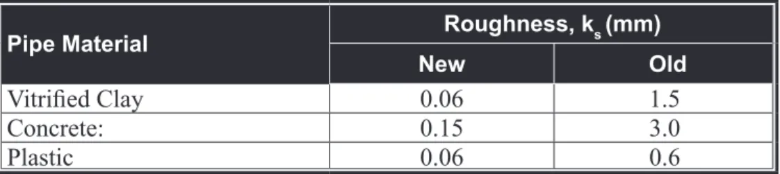
2.1.16 Pipe Roughness
Except for very high velocities, slime will always be present, which will increase the pipe roughness. Abrasion by sediments will also impart a permanent increase in roughness. Pipeline roughness decreases as the velocity increases. However, there is insufficient data to accurately determine the pipeline roughness for a wide range of velocities or at small incremental changes in velocity. In addition, the velocity of the sewage flow varies due to the factors such as daily fluctuations, different type of catchment, different stage of catchment maturity, etc. Therefore, it is not possible to select the pipe roughness with great accuracy. Conservative roughness values as given in Table 2.1 shall be referred to when determining sewer discharge capacity.
Table 2.1a Normal Pipe Roughness for Gravity Sewer
Pipe Material Roughness, ks (mm)
New Old
Vitrified Clay 0.06 1.5
Concrete: 0.15 3.0
Plastic 0.06 0.6
Old and new roughness values shall be used to determine the sewer cleansing and maximum design velocities respectively.
Table 2.1b Normal Pipe Roughness for Force Mains for All Pipe Materials
Mean Velocity, V (m/s) Roughness, ks (mm) 0.8 ≤ V < 1.5 0.6
1.5 ≤ V < 2.0 0.3
V ≥ 2.0 0.15
2.1.17 Design of Gravity Sewer
Unless special arrangements have been agreed for the structural protection of pipes, the minimum depth of soil cover over the sewer shall be 1.2 m. Sewers are not to be constructed under buildings.
The minimum size of public gravity sewers shall be 225 mm in diameter. The minimum size of domestic connections to the public sewer shall be 150 mm in diameter. The maximum design velocity at peak flow shall not be more than 4.0 m/s.
The design shall be based on the worst case scenario. The selection of the gravity sewer diameter and gradient to cope with the peak flow shall be based on the following equations:
1. Colebrook - White Equation
+ − = J'6 ' ' ORJ 6 ' J 9 ZKHUH 9 YHORFLW\ 6 K\GUDXOLFJUDGLHQWPP ν NLQHPDWLFYLVFRVLW\RIZDWHUPV ' LQWHUQDOGLDPHWHUP J DFFHOHUDWLRQGXHWRJUDYLW\PV NV URXJKQHVVFRHIILFLHQWP NV ν
Typical ks values for various types of sewer pipes are presented in Table 2.2 below:
Table 2.2 Typical Roughness Coefficient, ks
Material Roughness Coefficient, ks (mm)
Concrete 0.3 to 3
Cast iron 0.26
Asphalted cast iron 0.12
Ductile iron 0.046 2. Manning Equations 9
=
5
Q
6
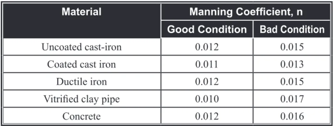
ZKHUH 9 YHORFLW\PVHF 6 K\GUDXOLFJUDGLHQW 5 K\GUDXOLFUDGLXV Q 0DQQLQJFRHIILFLHQWTypical n values for various types of sewer pipes are presented in Table 2.3 below:
Table 2.3 Typical Manning Coefficient, n
Material Manning Coefficient, n
Good Condition Bad Condition
Uncoated cast-iron 0.012 0.015
Coated cast iron 0.011 0.013
Ductile iron 0.012 0.015
Vitrified clay pipe 0.010 0.017
3. Hazen - Williams Equations 9
&5
6
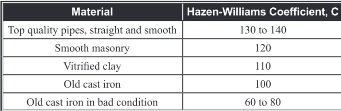
ZKHUH 9 YHORFLW\PVHF 6 K\GUDXOLFJUDGLHQW 5 K\GUDXOLFUDGLXV & +D]HQ:LOOLDPVFRHIILFLHQWTypical C values for various types of sewer pipes are presented in Table 2.4 below:
Table 2.4 Typical Hazen-Williams Coefficient, C
Material Hazen-Williams Coefficient, C
Top quality pipes, straight and smooth 130 to 140
Smooth masonry 120
Vitrified clay 110
Old cast iron 100
Old cast iron in bad condition 60 to 80
Colebrook-White Equation has been deemed to give the most accurate results. However, the other equations, such as Hazen-Williams Equation and Manning Equation are easier to use and may be used too. Various design charts and tables have been developed elsewhere to aid the manual computations.
2.1.18 Design of Force Mains
The minimum diameter of force mains (also known as rising mains) shall be 100 mm diameter. There shall be no reduction in force main diameter with distance downstream.
All bends on force mains shall be securely anchored to resist lateral thrusts and subsequent joint movements.
Air release valves and washouts shall be provided at appropriate locations along the longitudinal profile.
For long and undulating force mains, hydraulic pressure transient analyses may be required to ensure that the force main can cope with water hammer pressures.
Retention times in force mains must not exceed 2 hours without special precautions to mitigate septicity.
All force main shall be designed to withstand at least 1.5 times the working pressure. Approval from the Commission is required if any force main is to be designed to withstand pressure less than the pressure stated above.
Where retention times in the force mains exceed two hours and where concrete pipe are laid downstream of the force mains, an induct vent shall be provided at manholes receiving pumping discharges.
Friction losses are normally calculated using either Darcy-Weisbach (Colebrook-White) Equation or Hazen-Williams Equations. The forms of the equations are different from the equations used to design gravity sewers. The equations are listed below:
1. Darcy-Weisbach Equation ZKHUH KI )ULFWLRQORVV I &RHIILFLHQWRIIULFWLRQ 9 9HORFLW\LQWKHSLSH J $FFHOHUDWLRQGXHWRJUDYLW\ ' (TXLYDOHQWGLDPHWHURIWKHSLSH / /HQJWKRISLSH K I/9 J' I =
The value of f is known to depend on the Reynolds number, Re, pipe roughness, ks, and pipe diameter, D, through the Colebrook-White equation as follows: ORJ NV I ' 5H I 5H 9' Y
The Reynolds number is defined as follows:
where v is the kinematic viscosity of the fluid, typically equal to 1 x 10⁻⁶ m2/s for sewage.
determine the coefficient of friction, f. 2. Hazen-Williams Equation
K
9
&
/
'
I=
ZKHUH KI )ULFWLRQORVV & +D]HQ:LOOLDP&RHIILFLHQWUHIHUWR7DEOH 9 9HORFLW\LQWKHSLSH / /HQJWKRISLSH ' (TXLYDOHQWGLDPHWHURIWKHSLSHForce mains shall be designed to handle the full range of flows from present minimum to future peak.
The design velocity shall fall within the range of 0.8 to 3.0m/sec over the full range of design flows.
The hydraulic resistance of force main fittings and bends shall be included in the hydraulic design.
2.1.19 Vacuum Sewerage System
The design requirements of this Guidelines are the minimum requirements, and do not constitute in themselves a comprehensive design guide sufficient to ensure a correctly functioning system. Every system must be individually designed, based on the design parameters of the system employed; where proprietary systems are employed, it shall be designed in compliance with the requirements of system manufacturers.
2.1.19.1 General
Specification of a vacuum sewage collection system shall only be considered where the life-cycle costs of a conventional gravity sewage collection system are clearly shown to be higher.
This Guidelines assumes that all sewage transportation modes have been identified, their respective feasibilities evaluated against technical, environmental, financial, economic and other relevant criteria over the design life of the asset and that vacuum sewage collection system has been confirmed as the best option. The Commission may request for net present value (NPV) calculations for all options prior to approving construction of a vacuum sewage collection system.
I) Application of Vacuum Sewerage Collection System
Consideration shall be given to the use of the vacuum system in one or more of the following circumstances:
a) Flat or undulating terrain.
b) Obstacles to the sewer route eg utility services, waterways. c) Poor ground subsurface eg high ground water table, rocky
terrains.
d) Isolated, low density communities.
e) Where it is necessary to minimise the impact of construction work.
f) Where it is necessary to minimise the environmental impact. II) Unit Processes
Typical unit processes for a vacuum sewerage collection system is shown in typical drawing in Appendix A. The unit processes shall comprise of, but not limited to, the followings:
a) Collection chamber for housing vacuum interface valve and also forming a sump from which collected sewage is evacuated. b) A vacuum sewer network for the transport of sewage collected
in the collection chambers to a central vacuum station.
c) A central vacuum station where the vacuum pressure is generated which allows the sewage to be collected and forwarded to a receiving gravity sewer manhole or a sewage treatment plant. III) Description of System
a) Collection Chamber and Vacuum Pipeline
When the volume of sewage draining into a collection chamber reaches a predetermined level in the sump, the normally closed interface valve opens. The differential pressure between the vacuum sewer and atmosphere forces the sewage from the collection chamber into the vacuum sewer via a crossover pipe. Typical crossover pipe connection is shown in typical drawings in Appendix A. After the sump is emptied, the valve closes. Air is admitted simultaneously with, or after, the admittance of the sewage. The sewage is driven along the sewer until frictional and gravitational forces eventually bring it to rest in the lower section of the pipe profiles. The characteristics of the vacuum sewerage system ensure that peak discharges into the sewer are rapidly attenuated.
The vacuum sewer discharges into the vacuum vessel at the vacuum station. The vacuum is maintained by vacuum pumps at a predetermined level. The sewage is generally pumped from the vacuum station by
b) Vacuum Station
The vacuum station is similar to a conventional pump station with the addition of vacuum pumps and a closed vacuum vessel. Typical vacuum station is shown in typical drawings in Appendix A. The levels of the sewage in the vacuum vessel are monitored by a set level detection probes which activate the sewage discharge pumps. If the sewage rises too high in the vessel then a high level detection probe stops and locks out the vacuum pumps to prevent the flow of sewage into the vacuum vessels. The vacuum in the vacuum vessel is maintained within the operational range by pressure switches. c) Warranty of System Performance
Since the vacuum system involves proprietary design and equipment, specialised system designers shall be accountable to the performance of the entire vacuum system including both design and construction aspects. The specialised system designers shall also specify clearly the specific maintenance and operational requirements of the system. 2.1.19.2 Collection Chamber
I) General Design Requirements
Collection chambers shall have sufficient capacity to store sewage discharged from all connected properties for at least 6 hours in the event of a valve failure or similar emergency, which is sufficient to cover the Services Licensee emergency response time.
The overflow storage time shall be based on the ultimate sewage design flow that will enter the collection chamber. The volume that can be used for emergency storage shall be the volume contained in the collection chamber from the base of the collection chamber up to the lowest ground level at any point served by the chamber as well as the volume contained in the gravity lateral sewers entering the collection chamber.
Separate chambers shall be provided to serve properties at different elevations where there is a likelihood of sewage from one property flooding another property.
The chamber shall resist external forces and internal water pressure.
pre-cast concrete. The two sections (the valve compartment and the collection sump) may be mounted vertically one on top of the other as shown in typical drawings in Appendix A. The diameter of the sections may be as small as 1200 mm or as large as 1500 mm. The collection sump requires a benching section that allows a scouring action from the sewage as it enters the suction pipe, thereby rendering the sump self-cleansing. The internal surfaces of the sump shall be both strong as well as resistant to corrosive attacks from the collected sewage.
Where the interface valve is situated over the collection sump, a working platform shall be provided for allowing maintenance personnel to stand on when carrying out scheduled maintenance to the interface valve.
The sump shall be sufficiently vented to allow the intake of air without causing a noise nuisance and to ensure that the operation of the vacuum system does not unseal the water traps on the gravity drainage system.
II) Number of Properties Connected
The location of each collection chamber and the number of properties connected to each collection chamber shall be specified in the design drawings / calculations.
Sewage flow from the maximum number of existing or future properties that are proposed to be connected to a collection chamber shall be quantified, and the retention time of the collection chamber can be then established. The retention time shall exceed 6 hours.
III) Maximum Flows to Collection Chambers
The maximum sewer design flow to a single vacuum interface valve collection chamber shall not exceed 0.25 l/s. Where single point flows in excess of 0.25 l/s occur, multiple vacuum interface valves shall be installed. Typical multi-valve collection chamber is shown in typical drawings in Appendix A.
IV) Breather Pipes
Some vacuum interface valves inhale and exhale air during their operation. This is accomplished through a screened air pipe known as a “breather”.
While breather bells are generally mounted inside the collection chamber, it may be necessary to mount them externally.
Each breather pipe shall be fitted inside the “breather bell” located at the top of the collection chamber in an accessible location to allow their removal for maintenance purposes.
V) Covers and frames
Collection chamber covers shall provide an access opening of at least 600 mm diameter. Covers and frames shall be installed in accordance with the requirements stipulated in Clause 2.3.
2.1.19.3 Vacuum Interface Valves I) General
The interface valve shall fail safe in the closed position and shall prevent backflows from the crossover pipes to the collection sump. When the valve is open, the flow path shall not be obstructed by the valve mechanism. The valve shall evacuate at least the batch volume each time per cycle. Valves installed in the sump shall be capable of operating when submerged provided that the breather pipe is not submerged.
The valve shall be installed in the collection chamber using demountable, re-useable “ No Hub” couplings suitable for vacuum service.
II) Level Sensor
The valve shall be equipped with a sensor to determine the level of sewage in the collection sump; this sensor shall be designed to be fouling resistant. Level sensor pipes shall not be less than DN/ID 45.
III) Interface Valve Controller
The controller shall open the valve only if there is a minimum partial vacuum of 0.2bar below atmospheric available and shall maintain the valve fully open until at least the batch volume has been evacuated. If the design provides for the introduction of air after the sewage has been evacuated, the controller shall maintain the valve open for a further period. The controller shall be adjustable so that a range of air to sewage ratios can be obtained. Controllers installed in sumps shall be capable of operating when submerged.
IV) Explosion Proof
The valve mechanism and controller shall be explosion proof if exposed to potentially explosive atmosphere.
V) Life of Valves and Membranes
Every interface unit, comprising the interface valve, controller and sensor shall be expected to last in excess of 25 years. Manufacturers shall clearly specify scheduled maintenance, thus allowing the operators to keep the interface units in tip-top conditions at all times.
2.1.19.4 Vacuum Sewer Design I) General
For a completely flat area, the length of a single sewer branch shall not be more than 3 km. However, the maximum limit of the pipe length would vary according to the gradient achievable in that line. Specialised system designer shall provide a detailed hydraulic calculation for the vacuum sewer network.
Vacuum main routes shall be selected to: a) Minimise lift.
b) Minimise length.
c) Equalise flows on each vacuum main.
d) Provide adequate access for operation and maintenance. II) Sewer Depth
Vacuum sewers, branch sewers and crossover pipe connections from the collection chambers, shall have a minimum cover of 0.9 m to withstand the stresses arising from traffic loads.
When sewers are not buried, they shall be protected from extremes of temperature, ultra-violet radiation and possibility of vandalisms. When sewers are suspended underside walkways or bridges, they shall be rigidly supported so there is no visible sagging between supports. Supports shall withstand all static and specified dynamic conditions of loading to which the piping and associated equipment may be subjected. As a minimum, consideration shall be given to the following conditions:
a) Weights of pipe, valves, fittings, pipe protection materials, and medium in the pipe.
b) Reaction forces due to the operation of isolation valves. c) Wind loadings on outdoor piping.
III) Sewer Profiles
Pipeline profiles shall be self cleansing and prevent the accumulation of solids. Typical pipeline profiles are shown in typical drawings in Appendix A. For crossover pipes, the minimum distance between lifts shall be 1.5 m. Vacuum sewers shall have a minimum gradient of 1 in 500. Where the ground has a gradient of 1 in 500 or more in the direction of flow, the vacuum sewer may be laid parallel to the surface as shown in typical drawings in Appendix A.
a) Design Tolerances
The chainage and invert levels of the pipeline(s) shall be determined to the following levels of design accuracy and specified in the Design Drawings:
i) Sewer chainage to the nearest 0.5 m. ii) Sewer invert levels to the nearest 0.01 m. b) Lift Design
To provide for efficient vacuum transport to sewer extremities, the size of individual lifts shall be kept as small as possible. Many small lifts are preferable to one large lift. The change in invert at each lift shall not exceed 1.5 m. For vacuum sewers, the minimum distances between lifts shall be 6 m.
c) Crossover Pipe Connection
Crossover pipe shall initially fall away from the interface valve and shall connect into the top sector of the vacuum sewer contained within the angle of ± 60° about the vertical axis as shown in Appendix A.
d) Branch Connections
All branch connections to vacuum sewers shall be by a Y-junction connected to the sewer above the horizontal axis as shown in Appendix A. In plan, the angle of the Y-junction shall ensure that flow towards the vacuum station is generated and backflows are minimised. No connection shall be made within 3m of a lift.
e) Water-logging
The profile shall ameliorate water-logging at any change in gradient even when a prolonged power failure occurs (both TNB supply and standby genset fail), and the vacuum interface valves continue to operate and admit sewage until the vacuum level reduced to the point when they will no longer open. When the power is again available, the system shall be capable of recovering to normal operation without intervention by an operator.
IV) Pipework and Fittings for Vacuum Sewers
The recommended material from which to construct vacuum sewers is minimum PE 80-PN 8 rated solid wall polyethylene pipe. Pipe fittings shall be PE 100-PN 8. Pipes shall be UV stabilised with carbon black which shall give the pipe a black colour throughout. The polyethylene pipe is selected because it is both structurally strong and compatible with potentially chemically aggressive and abrasive flows in the sewage.
a) Pipe Size
The suction pipe DN/ID shall not be greater than the DN/ID of the interface valve. The minimum diameter of crossover pipe shall be DN/ID 50 and shall be greater than the DN/ID of the suction pipe. Vacuum sewer shall have a minimum diameter of DN/ID 80.
b) Jointing of PE Pipes and Fittings
PE pipes and fittings less than DN 160 shall be jointed using electrofusion fittings. Pipes and fittings DN 160 and larger shall be jointed with electrofusion fittings or butt fusion welding.
c) Warning System
To act as a warning to an excavation possibly carried out at a later date, the use of a marker tape laid 300 mm on top of the pipe is recommended. This shall be a 150 mm wide polyethylene and printed with a descriptive warning of the pipeworks below.
V) Isolation Valve
The isolation valve clear opening shall be not less than the DN/ID of the pipe, and be capable of sustaining a vacuum pressure of -0.8
Isolation valves shall be resilient seated gate valves with the body, bonnet, gate and bridge fabricated from ductile or cast iron. The stem shall be stainless steel, and the gate shall be encapsulated with Ethylene Propylene Diene Monomer (EPDM). End connections to the valves shall be flanged.
a) Isolation Valve Installation
Each isolation valve shall be located in a chamber, which shall contain a dismantling arrangement for replacement of the isolation valve if needed.
When isolation valves are buried, they shall have extension spindles and surface boxes.
b) Isolation Valve Location
Means of isolating lengths of vacuum sewer to permit repairs or to locate faults shall be provided at distances of not more than 500 m and on branch sewers longer than 200 m.
2.1.19.5 Vacuum Station Design I) General
It is desirable to have the vacuum station located as centrally as possible within the sewer network. This lends itself to a system with multi-branches hence giving added operating and design flexibility. Ideally, the design capacity of a single-vessel vacuum station shall not exceed a population equivalent of 8000 persons.
A dual-vessel station, or more than a single-vessel station that is completely isolated, shall be provided when the population equivalent exceeds 8000 persons.
II) Vacuum Station Layout
A typical vacuum station layout is shown in typical drawings in Appendix A. The vacuum station shall be divided into two main areas, an above ground plant room and a below ground dry well. The floor level of the dry well shall be designed to suit the invert levels of the incoming sewers, the vacuum vessel diameter and the dimensions of the selected sewage discharge pumps.
The vacuum vessel, the sewage discharge pumps, valves and pipework associated with the sewage discharge pumps and a small sump to collect washdown water shall be located in the dry well.
The plant room shall contain the vacuum pumps, control panel, standby diesel generator, vacuum pressure gauges, and moisture trap.
III) Vacuum Vessel
Vacuum vessels shall be designed to meet the requirements of ASME Section VIII Division 1 – 2004 Edition. The vessel shell shall be constructed from mild steel or any other approved material.
Sewer inlets shall be provided with short radius elbows inside the vessel to direct the sewage inflow away from the sewage discharge pump suction connections and the vessel walls.
A vacuum vessel may have up to five (5) incoming vacuum sewers connected directly to the vessel. No inlet pipes shall be connected below the system emergency stop level. Sewage discharge pump suction connections shall be provided at the invert of the vacuum vessel. The vacuum vessel shall be fitted with an externally mounted sight glass which is suitable for operation in a vacuum and is easily removed for cleaning without decommissioning the vessel.
The vacuum vessel shall be provided with a DN 600 access opening, and the cover shall be provided with a lifting eye. Wherever possible, the opening is preferably positioned on the top of the vessel in order to minimise the size of the structure necessary to house the vessel, this conserves valuable resource, reduces the footprint of the building, and thus allows adjacent residences to enjoy more buffer spaces. During the inspection or maintenance works, safe entry procedures shall be adhered to, according to the Department of Occupational Safety and Health (DOSH) codes of laws, by trained certificated operator, and that the vessel is decommissioned, with the access opening removed and discharge pipeworks at the two (2) draw-off points dismantled, and a forced air ventilation is applied.
It is important to ensure that the system would operate continuously in the face of having the vacuum vessel temporarily out of service during an interval inspection. The incoming sewage shall manually be bypassed to a mobile vacuum tanker via a flexible ribbed pipe.
The pipe is of an adequate length to reach the bypass valves safely. Typical bypass valve arrangement is shown in typical drawings in Appendix A.
VI) Moisture Trap
When mechanical vane vacuum pumps are selected, moisture trap shall be provided for the vacuum pumps.
Baffles or moisture removing material shall be fitted inside each vessel to assist with moisture removal.
V) Vacuum Pumps
Vacuum pump capacity (Qvp) shall be rated. The selection of appropriate size of vacuum pump is determined by the following four
factors:-a) The peak flow of the sewage to be collected.
b) The length of the longest single sewer within the sewer network.
c) The total volume of the sewer pipework within the network. d) Air to liquid ratio employed (ratio not less than 3).
a) Evacuation Time
When the vacuum pumps, collection chamber and vacuum vessel have been sized, system evacuation time for an operating range of – 0.55 bar(g) to –0.65 bar(g) shall be calculated using:
(
)
4YS 9PW 9R 9YY 9YV W × + − + = :KHUH W V\VWHPHYDFXDWLRQWLPHPLQXWHVNOTE: In normal operation it is assumed that the vacuum sewers will be approximately 1/3 liquid filled.
The system evacuation time, which is defined as the time period between the vacuum pump start and stop, shall be between 2 and 5 minutes.
b) Selection of Vacuum Pumps
Vacuum pumps shall have sufficient capacity to serve the system. A minimum of two vacuum pumps of equal capacity shall be installed such that one pump can be removed for maintenance without the loss of system capacity. Vacuum pumps, where used, shall be suitable for both continuous operation and for a minimum of 6 starts per hour. c) Vacuum Pipework
ABS pipes and fittings shall be used for interconnecting pipework between the vacuum pumps and the vacuum vessel within vacuum stations.
Pipework shall be fully supported. VII) Sewage Discharge Pumps
Two sewage discharge pumps of equal capacity are recommended for use in a vacuum station. Each pump shall be sized to discharge sewage at a rate at least equal to the calculated design peak flow for the vacuum system. Sewage discharge pumps shall be capable of pumping unscreened sewage and suitable for immersed operation in the event of the vacuum station dry-well flooded. In normal operation the dry-well will not contain water.
Pumps may have a vertical or horizontal configuration.
Sewage discharge pumps shall be suitable for a minimum of 6 starts per hour. Equalising lines connecting the discharge side of the centrifugal sewage discharge pumps to the vacuum vessel shall be installed if required to prevent cavitation or to ensure that the pump inlet is always flooded.
Sewage discharge pumps shall be fitted with isolation valves to allow removal of the pump without disrupting the system operation.
valve and a resilient seated gate valve on the discharge side. Where the discharge pipework is manifold, the final discharge pipe shall also be fitted with a non return valve. The valves shall be able to be operated from the vacuum station floor.
VIII) Vacuum Gauges
150mm vacuum gauges calibrated to read 0 to -1 bar to an accuracy of ±2% shall be fitted to the vacuum vessel and each incoming vacuum sewer. Vacuum gauges shall also have bottom outlets fitted with lever-operated ball valves. All gauge diaphragms shall be suitable for use with sewage gases. The gauges indicate the vacuum pressure within each sewer and enable pressures within the sewer network to be monitored.
IX) Fire-fighting System
Fire-fighting system using carbon dioxide at the genset / fuel room shall be provided at every vacuum station in accordance with Bomba’s requirements.
X) Odour Control
Effective odour control system shall be provided to treat air vents from a vacuum station to prevent malodour impacts being imposed on downstream residential areas.
Biofilters is one of the systems used to remove the odours from the vacuum pump exhaust gases containing toxic and odorous compounds by passing the gases through a natural biologically active filter medium.
XI) Noise Control
Vacuum station shall be acoustically designed and fitted with noise control measures, as required to control noise to levels that comply with local council’s regulations.
XII) Controls and Telemetry a) Vacuum Level Control
Vacuum levels in the vacuum vessel shall be controlled by vacuum switches with operating range of 0 to -1 bar(g). Their purpose is to control the operation of the vacuum pumps and to maintain the vacuum within the vessel inside the operating range. A minimum of four vacuum switches shall be provided to operate the duty and assist pumps, and to provide a high and a low vacuum alarms.
b) Level Control
The level detection probes shall be mounted on the vacuum vessel. The purposes are to control the operation of the sewage discharge pumps and to maintain the sewage within the vessel inside the operating range.
Probes shall be manufactured in one length without any screw joints along their length. Any form of float switch, including magnetic and ultrasonic types shall not be permitted.
The level control system shall respond to the following sewage levels in the vacuum vessel:
Emergency stop level - stops vacuum generation;
- sewage discharge pump operates; Start level - starts sewage discharge pump; Stop level - stops sewage discharge pump; c) Vacuum / Sewage Discharge Pump Control
The controls shall permit the selection of duty, duty assist (where provided) and standby vacuum pumps and sewage discharge pumps and shall provide for the automatic introduction of the standby units in the event of failure.
The electrical controls shall allow sequential operation of all pumps so that running times are equalised. The standby pump shall automatically cut-in should the duty pump fail.
d) Valve Monitoring System / Station Telemetry
Valve monitoring and station telemetry systems are optional, but, shall be implemented for larger schemes comprising more than 50 interface valves.
The open and closed status of interface valves shall easily be detected by the use of a remote control via infrared/radio signals. Alternatively, system suppliers may install a signal cable to relay this information to a display panel within the vacuum station. All monitoring components installed at the collection chambers shall be robust and suitable for use in sewerage application.
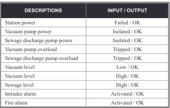
Large schemes shall also include a telemetry section with volt-free contacts for each condition/alarm of the station equipment as shown
Table 2.5 Condition/alarm of the Station Equipment
DESCRIPTIONS INPUT / OUTPUT
Station power Failed / OK
Vacuum pump power Isolated / OK
Sewage discharge pump power Isolated / OK Vacuum pump overload Tripped / OK Sewage discharge pump overload Tripped / OK
Vacuum level Low / OK
Vacuum level High / OK
Sewage level High / OK
Intruder alarm Activated / OK
Fire alarm Activated / OK
XIII) Emergency Power Generation
A back-up diesel generator shall be provided to adequately run the station in the event of an electric power disruption. The generator shall be capable of providing 120% of power for at least one vacuum pump and one sewage discharge pump and other necessary equipment.
2.1.20 Computerised Sewer Designs
Manual computations for the hydraulic design of a sewer network can be avoided for many aspects using proprietary computer software or in-house computer programs. However, there are many variations possible for the different aspects of hydraulic design, i.e. flow contributions from different sources, quantity of infiltration, quantity of inflow, sediment cleansing requirements, pipeline roughness coefficients, etc. It is therefore necessary that the computer software or programs adopt the hydraulic design requirements as detailed in this guideline. Some proprietary softwares may not permit certain adaptations required to conform to the hydraulic design requirements given in this guideline. As such, these software would be unsuitable.
2.1.21 Design of Inverted Siphon
under an obstacle (e.g. railway line, stream, culvert, etc). An alternative to an inverted siphon for bypassing obstacles is a pump station. But such an option may be economically not viable. The profile of an inverted siphon encourages solids settlement and accumulation and therefore they require more frequent cleaning. They must be avoided as much as practicable.
Inverted siphon shall consist of at least two or more parallel pipelines (or barrels). The minimum pipe size of a barrel shall be 225 mm, and shall be provided with necessary appurtenances for convenient flushing and maintenance. There will be an inlet chamber designed to divide the flow among the pipes by allowing each pipe to come into operation in succession and an outlet chamber designed to prevent eddies from carrying solids and sediments back into the siphons.
Longer siphons shall be provided with hatch box with access for maintenance and cleaning. These siphons shall have independent washout facilities.
The manholes shall have adequate clearance for rodding. In general sufficient head shall be provided and pipe sizes selected to secure flow velocities of at least 0.9 m/sec for average flow. The inlet and outlet shall be arranged so that the normal flow is diverted to one barrel, and so that either may out of service for cleaning. Its choice should be taken into consideration the operational and maintenance aspect of siphons. The siphons shall not have sharp bends, either vertical or horizontal. The horizontal leg of the siphon shall have a negative gradient of 8° to 10°, whilst the rising leg shall be limited to 30° to 45° should space permitting. There shall be no change in pipe diameter along the length of the barrel. Pipes and pipe joints used for siphons shall be designed at the appropriate pressure rating.
2.1.22 Structural Design of Sewers
The structural design of a buried sewer can be divided into the following two categories:
a) Rigid pipe. b) Flexible pipe.
All two structural designs shall take account of how the sewer is supported to determine the loading which the sewer can safely withstand.
The structural design of a buried sewer normally considers only the structural integrity of the pipe cross section. Although not as critical as
the structural integrity of the pipe cross section, the considerations for the ground conditions and sewer installation practices that will affect the longitudinal structural integrity shall not be omitted.
There are many design approaches for each of the two structural design categories. However, there are only minor alterations among these different approaches. Some design approaches tend to give a more favourable prediction of performance for a particular pipe material than other approaches. The use of standard design approaches given in this guideline will prevent the selection of a particular design approach purely to favour one material over another. Also, the following recommendations are only meant for general design aspects. Any design aspects that are not covered by this Volume, the designer shall refer to BS EN 752 or any other standards deemed appropriate by the Commission.
a) Rigid Pipe Structural Design Pipes which are classified as rigid are: i) Vitrified clay (VC) pipe.
ii) Reinforced concrete (RC) pipe.
The failure of a rigid pipe normally occurs by pipe fracture. Thus, for structural performance, the determination of the pipe ring crushing strength / load is required. This strength is determined using three points loading test as described in the respective Malaysian Standards for the above pipes. Both VC pipe and RC pipe can be made to achieve different ring strengths as defined in the Standards.
When a buried rigid pipe is supported, the load which the pipe can safely withstand is higher than the load which caused failure in the three point loading test.
The improvement in load resistance provided by different pipe support designs is defined by the bedding factor. Where the sewer is supported on granular material, such as crushed rock, the bedding factor becomes a function of the density of the granular material and the height to which the granular material is placed above the sewer.
By varying the pipe ring strength and the pipe support, different load resistance can be achieved.
The pipe support designs permitted by this Volume are limited to those in typical beddings in Appendix A. They include the following: