European Telecommunications Standards Institute
Technical Report
Digital Video Broadcasting (DVB);
Interaction channel for Satellite Master Antenna TV (SMATV)
distribution systems;
Guidelines for versions based on satellite and coaxial sections
EBU UER
Reference
DTR/JTC-00DVB-67 (b4c00ics.PDF)
Keywords
DVB, broadcasting, digital, video, MPEG, TV, SMATV, interaction
ETSI Secretariat
Postal address
F-06921 Sophia Antipolis Cedex - FRANCE
Office address
650 Route des Lucioles - Sophia Antipolis Valbonne - FRANCE
Tel.: +33 4 92 94 42 00 Fax: +33 4 93 65 47 16
Siret N° 348 623 562 00017 - NAF 742 C Association à but non lucratif enregistrée à la
Sous-Préfecture de Grasse (06) N° 7803/88
X.400
c= fr; a=atlas; p=etsi; s=secretariat
Internet
[email protected] http://www.etsi.fr
Copyright Notification
No part may be reproduced except as authorized by written permission. The copyright and the foregoing restriction extend to reproduction in all media.
© European Telecommunications Standards Institute 1997. © European Broadcasting Union 1997.
Contents
Intellectual Property Rights...5
Foreword ...5
Introduction ...6
1
Scope ...9
2
References...9
3
Definitions and abbreviations ...11
3.1 Definitions ... 11
3.2 Abbreviations... 11
4
System architecture of narrow-band interaction channel...13
4.1 Protocol stack model... 13
4.2 System model... 14
4.3 Application of the reference model... 15
5
IC for SMATV systems based on satellite and coaxial sections ...17
5.1 Satellite section ... 18
5.1.1 Satellite multiple access technology and access control... 19
5.1.2 Antenna size and power amplifier ... 20
5.2 Coaxial section... ... 21
5.2.1 Spectrum allocation... 22
5.2.2 FDM/TDMA multiple access ... 23
5.2.3 Bit rates and framing ... 24
5.3 Satellite-coax interface... 25
5.3.1 RS-232 serial interface ... ... 25
5.3.1.1 Mechanical and electrical characteristics... 25
5.3.1.2 Framing... ... 26
5.3.1.3 Flow control mechanisms ... 26
5.3.2 Alternative interfaces ... 26
5.3.2.1 LAN based interfaces ... 26
5.3.2.2 X.25 communications interfaces... 26
6
Implementation examples for the satellite section...27
6.1 Asymmetric services scenario for interactive broadcasting applications ... 27
6.1.1 Example based on TDMA with fixed assignment ... 27
6.1.2 Example based on CDMA with Slotted Aloha ... 28
6.1.3 Performances, advantages and limitations of the two examples ... 30
6.2 Scenario oriented towards Multimedia services... 30
Annex A (informative):
Satellite link budget examples ...31
A.1 16 kbit/s carriers; TDMA + fixed assignment access protocol ... 31
A.2 16 kbit/s carriers; CDMA + Slotted Aloha access protocol ... 32
A.3 256 kbit/s carriers; TDMA + Slotted Aloha access protocol ... 33
Annex B (informative):
ETSI VSAT standards vs. DVB SMATV Interaction Channel...34
B.1 Safety ... 34
B.2 RF performance ... 35
B.3 Control and Monitoring Functions (CMF)... 36
B.4 Analysis of specified parameters for several scenarios ... 36
B.4.1 Off-axis EIRP emission density... 37
B.4.1.1 Scenario based on TDMA ... 37
B.4.1.2 Scenario based on CDMA ... 37
B.4.2 Antenna transmit gain pattern... 38
B.4.3 Transmit polarization discrimination... 38
B.4.4 Receive polarization discrimination ... 38
B.4.6 Polarization angle capability ... 39
Intellectual Property Rights
IPRs essential or potentially essential to the present document may have been declared to ETSI. The information pertaining to these essential IPRs, if any, is publicly available for ETSI members and non-members, and can be found in ETR 314: "Intellectual Property Rights (IPRs); Essential, or potentially Essential, IPRs notified to ETSI in respect of
ETSI standards", which is available free of charge from the ETSI Secretariat. Latest updates are available on the ETSI
Web server (http://www.etsi.fr/ipr).
Pursuant to the ETSI Interim IPR Policy, no investigation, including IPR searches, has been carried out by ETSI. No guarantee can be given as to the existence of other IPRs not referenced in ETR 314 (or the updates on http://www.etsi.fr/ipr) which are, or may be, or may become, essential to the present document.
Foreword
This Technical Report (TR) has been produced by the DVB Project and submitted for publication to the Joint Technical Committee (JTC) of the European Broadcasting Union (EBU), Comité Européen de Normalisation ELECtrotechnique (CENELEC) and the European Telecommunications Standards Institute (ETSI).
The present document has been produced by the specialized group DVB-RC of the Technical Module of the DVB Project. An interest group, made-up by the European Satellite Operators, has reviewed and agreed the text, based on the contributions made by the European DIGISAT project.
The DIGISAT project is an European project of the ACTS Programme, partially funded by the European Commission, and with the sponsorship of the European Space Agency (ESA).
Advanced Communications, Technologies and Services (ACTS) is the European Commission Research and Development Programme. One of its projects is DIGISAT, which has contributed significantly to the solutions of Interaction Channel for SMATV networks, described in the present document.
NOTE: The EBU/ETSI JTC was established in 1990 to co-ordinate the drafting of standards in the specific field of broadcasting and related fields. Since 1995 the JTC became a tripartite body by including in the Memorandum of Understanding also CENELEC, which is responsible for the standardization of radio and television receivers. The EBU is a professional association of broadcasting organizations whose work includes the co-ordination of its members' activities in the technical, legal, programme-making and programme-exchange domains. The EBU has active members in about 60 countries in the European broadcasting area; its headquarters is in Geneva *.
* European Broadcasting Union Case Postale 67
CH-1218 GRAND SACONNEX (Geneva) Switzerland
Tel: +41 22 717 21 11 Fax: +41 22 717 24 81 Digital Video Broadcasting (DVB) Project
Founded in September 1993, the DVB Project is a market-led consortium of public and private sector organizations in the television industry. Its aim is to establish the framework for the introduction of MPEG-2 based digital television services. Now comprising over 200 organizations from more than 25 countries around the world, DVB fosters market-led systems, which meet the real needs, and economic circumstances, of the consumer electronics and the broadcast industry.
Introduction
The present document provides guidelines and recommendations for the implementation of an Interaction Channel (IC) based on two way satellite links, to users connected to Satellite Master Antenna Television (SMATV) systems.
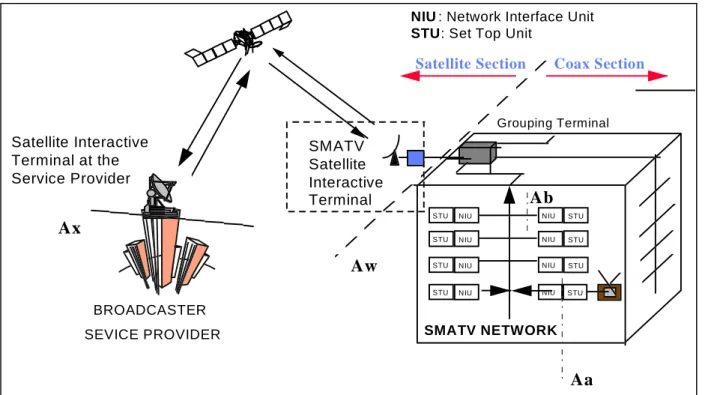
The system provides the IC through the concatenation of a satellite section and a coaxial section (see figure 1) in a seamless fashion. Guidelines and recommendations provided in the present document are valid for the implementation of very cost effective solutions matched to the SMATV scenario as well as for the reuse of already operating satellite networks which are currently installed in a huge amount of buildings throughout Europe.
NIU STU STU NIU STU NIU NIU STU NIU STU NIU STU STU NIU STU NIU Grouping Terminal
NIU : Network Interface Unit STU: Set Top Unit
SMATV NETWORK BROADCASTER SEVICE PROVIDER Satellite Interactive Terminal at the Service Provider
Satellite Section Coax Section
Aw
Ax
Aa
SMATV Satellite Interactive TerminalAb
Figure 1: DVB Interaction Channel for SMATV System overview
Research and Development activities carried out in the frame of the ACTS European Research Program have demonstrated the feasibility of the Interaction Channel for SMATV based on satellite and coaxial sections.
Tests and demonstrations show that this concept is a short term reality and that preliminary prototypes are available supported by the European industry.
The present document describes the key points of the system to cope with the commercial requirements established at the DVB for asymmetric interactive services supporting broadcast to home with narrow-band return channel
DVB Project (A008) [8].
The system described in the present document is an open system allowing the inter-operability between the two sections irrespective of the technology supported. Guidelines are provided in this sense, allowing the use of alternative
technologies for each section (satellite and coaxial cable) with the aim the users or operators can select the technology best suited for each situation depending on the type of SMATV network, required services, quality of services, number of users, traffic requirements, etc.
The SMATV coaxial section solutions described in the present document allow also the use of alternative delivery media such as terrestrial, microwaves, etc., facilitating in this way inter-operable DVB-RC systems for the SMATV environment.
The system described in the present document is compatible with the DVB network independent protocols for interactive services ETS 300 802 [12].
The present document provides reference examples for the implementation of an Interaction Channel system to cope with two different scenarios:
Scenario A:
An environment of asymmetric interactive services supporting broadcast to home with narrow-band return
channel.
It means the typical broadcasting scenario enhanced with low capacity interactive services, which implementation is foreseen to be massive in a short period of time.
Provided that the power required for the Satellite Interactive Terminals (SIT) within this scenario is rather low and considering that the use of very low cost terminals is required, the SIT becomes a differentiated concept from the typical Very Small Aperture satellite Terminal (VSAT) applications, currently working in the professional environment rather than in the consumer one, mainly because of the expected higher number of SIT.
Scenario B:
An environment oriented towards wide-band Multimedia services, where the satellite based infrastructure can play a very effective role.
The generic DVB reference model for interactive systems is followed by the system described in the present document. The Interaction Network is split into a satellite section, a coaxial section and an interface in-between. The satellite section provides the two ways communications between the roof of each building (Grouping Terminal (GT) at the SMATV head-end) and the service provider premises. The coaxial section provides the two ways communications between each User Terminal (UT) and the GT at the SMATV head-end which is located at the roof of each building. The Satellite Interactive Terminal (SIT) is the key equipment of the satellite section, which is composed by the RF antenna subsystem and the satellite modem to provide inter-activity to the SMATV users. One SIT would be needed per building although in some cases it might be convenient to collect the interaction traffic of several adjacent buildings into a single GT. For the satellite section, implementation examples are given for both identified scenarios and for different satellite network technologies such as Code Division Multiple Access (CDMA) and Time Division Multiple Access (TDMA) with the aim of showing the feasibility to implement open and inter-operable systems based on existing standards. In order to provide purely illustrative implementation examples, specific sizing examples are provided for hypothetical services and traffic scenarios, deriving antenna sizes, power required, possible configurations, etc.
The GT at the SMATV performs the collection and the distribution of information coming from and going to the UTs. It is composed by the GT Interactive Network Adapter (INA), the Medium Access Control (MAC) functions and the interfaces with the SIT in order to collect/distribute the information in the SMATV coax network related to each UT's Interactive Interface Module (IIM). For the coaxial section a subset of the options provided by the
DVB-RC-CATV (ETS 300 800 [9]) is recommended allowing a system simpler than the CATV one, thus matching the requirements of the SMATV scenario. One of the key elements of the SMATV scenario with respect to the CATV one is that the GT at the SMATV head-end is an equipment of a consumer type in a similar way as the Set Top Box (STB) is, although the SMATV head-end cost is shared among the users connected to the same SMATV network. Although the system proposed for the coaxial section is applicable for an extended range of SMATV systems, very small SMATV systems with a reduced number of users might require alternative optimized coaxial section solutions.
The interface between the coaxial and the satellite sections is defined with the aim of facilitating the interoperability between subsystems from different vendors and technologies. In principle a very low cost interface, RS-232 based, is recommended although alternative interfaces are identified in order to allow the use of existing equipment as well as to facilitate the provision of Multimedia broadband applications as identified in the scenario B above.
Due to the fact that the cost of the system is one of the major driving factors to ensure the commercial feasibility of Interaction Channel for SMATV, the system proposed takes advantage of the natural grouping of users in an SMATV system for sharing the cost of the SIT and the Grouping Terminal (GT) among the number of users living in the same building. The conclusion reached on the feasibility of the Interaction Channel for SMATV networks is also supported by the cost studies carried out to check the compliance against the DVB Project's Interactive Services Commercial Module (ISCM) user requirements.
Information on the key parameters of the existing ETSI standards on VSAT applicable to the SIT for the SMATV networks, are provided in order to check their adaptation to this scenario where profiles of consumer terminals should be reached, as well as to identify any potential action in the corresponding standardization bodies.
Alternative DVB Interaction Channel (IC) systems may be also used by SMATV users, as for example the Public Switched Telephone Network / Integrated Services Digital Network (PSTN/ISDN) (EN 300 801 [11]) and the wireless Digital Enhanced Cordless Telecommunications (DECT) solutions (EN 301 193 [26]).
The reference model is described in clause 4. In clause 5 the system proposed for DVB Interaction Channel (IC) for SMATV based on satellite and coaxial sections is described and recommendations are provided for the satellite section, the coaxial section and the interface between them. In clause 6 implementation examples of SIT implementation are provided for the two identified scenarios and for several configurations as illustrative examples. Annex A provides examples of satellite link budgets. Annex B provides information on the key parameters of the existing ETSI standards in reference to SIT.
1
Scope
The present document provides guidelines and recommendations for the implementation of an Interaction Channel (IC) based on two way satellite links, to users connected to Satellite Master Antenna Television (SMATV) systems.
The system provides the IC through the concatenation of a satellite section and a coaxial section in a seamless fashion. Guidelines and recommendations provided in the present document are valid for the implementation of very cost effective solutions matched to the SMATV scenario as well as for the reuse of already operating satellite networks which are currently installed in a huge amount of buildings.
The system described in the present document is an open system allowing the inter-operability between the two sections irrespective of the technology supported. Guidelines are provided in this sense, allowing the use of alternative
technologies for each section (satellite and coaxial cable) with the aim the users or operators can select the technology best suited for each situation depending on the type of SMATV network, required services, quality of services, number of users, traffic requirements, etc.
The present document provides reference examples for the implementation of an IC system to cope with two different scenarios:
Scenario A: asymmetric interactive services supporting broadcast to home with narrow-band return channel.
Scenario B: wide-band Multimedia services.
2
References
References may be made to:
a) specific versions of publications (identified by date of publication, edition number, version number, etc.), in which case, subsequent revisions to the referenced document do not apply; or
b) all versions up to and including the identified version (identified by "up to and including" before the version identity); or
c) all versions subsequent to and including the identified version (identified by "onwards" following the version identity); or
d) publications without mention of a specific version, in which case the latest version applies.
A non-specific reference to an ETS shall also be taken to refer to later versions published as an EN with the same number.
Because of the rapid development of specifications and standards it is recommended to verify in each case whether the following documents have been replaced by more recent versions. The following list was compiled in August 1997.
[1] EN 300 473: "Digital Video Broadcasting (DVB); Satellite Master Antenna Television (SMATV) distribution systems". Known as "DVB-CS".
[2] EN 300 421: "Digital Video Broadcasting (DVB); Framing structure, channel coding and modulation for 11/12 GHz satellite services". Known as "DVB-S".
[3] EN 300 429: "Digital Video Broadcasting (DVB); Framing structure, channel coding and modulation for cable systems". Known as "DVB-C".
[4] ETS 300 159: "Satellite Earth Stations and Systems (SES); Transmit/receive Very Small Aperture Terminals (VSATs) used for data communications operating in the Fixed Satellite Service (FSS) 11/12/14 GHz frequency bands". Now covered by ETS 300 784.
[5] ETS 300 161: "Satellite Earth Stations and Systems (SES); Centralized control and monitoring functions for Very Small Aperture Terminals (VSAT) networks".
[6] ETS 300 160: "Satellite Earth Stations and Systems (SES); Control and monitoring functions at a Very Small Aperture Terminal (VSAT)".
[7] ETS 300 194: "Satellite Earth Stations and Systems (SES); The interconnection of Very Small Aperture Terminal (VSAT) systems to Packet Switched Public Data Networks (PSPDNs)".
[8] DVB Project (A008): "Commercial requirements for asymmetric interactive services supporting broadcast to the home with narrow-band return channels".
[9] ETS 300 800: "Digital Video Broadcasting (DVB); Interaction channel for Cable TV distribution systems (CATV)".
[10] DVB Project: "Guidelines for the use of the Specification DVB Interaction Channel for Cable TV distribution systems (CATV)".
[11] ETS 300 801: "Digital Video Broadcasting (DVB); Interaction channel through Public Switched Telecommunications Network (PSTN) / Integrated Services Digital Network (ISDN)".
[12] ETS 300 802: "Digital Video Broadcasting (DVB); Network-independent protocols for DVB interactive services".
[13] TR 101 194: "Digital Video Broadcasting (DVB); Guidelines for implementation and usage of the specification of network independent protocols for DVB interactive services".
[14] prEN 50083: "Cabled distribution systems for television and sound signals".
[15] prEN 50166-2: "Human exposure to electromagnetic fields. High frequency (10 kHz to 300 GHz)".
[16] ITU-T Recommendation V.24: "List of definitions for interchange circuits between data terminal equipment (DTE) and data circuit-terminating equipment (DCE)".
[17] ITU-T Recommendation V.28: "Electrical characteristics for unbalanced doubled-current interchange circuits".
[18] ITU-T Recommendation X.25: "Interface between Data Terminal Equipment (DTE) and data Circuit-terminating Equipment (DCE) for terminals operating in packet mode and connected to public data networks by dedicated circuit".
[19] ISO 2110: "Data Terminal Equipment and Data Communications Equipment. Switching circuits. Application to the pin connectors numbering".
[20] ISO/IEC 8802-3 (ANSI/IEEE 802-3 Ethernet): "LAN/MAN CSMA/CD Access Method Standards Package".
[21] EIA 568 A: "Commercial Building Telecommunications Cabling Standards ISO/IEC 11801 Generic Cabling for Customer premises Cabling".
[22] DIGISAT ACTS project (Digisat-TN-056-HSA version 1.3): "Cost Analysis of the Interactive system for SMATV based on satellite and coaxial sections".
[23] DIGISAT ACTS project (Digisat-TN-09): "Traffic analysis for SMATV Interactive systems". [24] CENELEC EN 50201: "Interfaces for DVB-IRDs".
[25] EIA-232: "Interface between DTE and DCE employing serial binary data interchange". [26] prEN 301 193: "Digital Video Broadcasting (DVB); Interaction channel through the Digital
3
Definitions and abbreviations
3.1
Definitions
For the purposes of the present document, the following definitions apply:
Satellite Master Antenna TeleVision (SMATV) system: A SMATV system is defined as a system which is intended
for the distribution of TV, sound and Multimedia signals to households located in one or more adjacent buildings. These signals are received by a satellite receiving antenna and may be combined with terrestrial TV signals.
SMATV distribution systems are also known as community antenna installations or domestic TV cable networks. A SMATV system represents a means for sharing the same resource among several users for satellite and terrestrial reception. Two systems have been defined in EN 300 473 [1] for the satellite digital TV distribution through SMATV:
a) SMATV system A (SMATV-DTM): This system approach consist of the trans-modulation from satellite
Quaternary Phase Keying (QPSK) signals as defined in EN 300 421 [2] (DVB-S) to a Quadrature Amplitude Modulation (QAM) scheme as defined in EN 300 429 [3] (DVB-C). The process of trans-modulation without baseband interfacing is also known as Transparent Trans-modulation and the head-end unit performing this function is known as Transparent Digital Trans-modulator (TDT).
b) SMATV system B: This system is based on the use of QPSK modulation. The SMATV system B concept allows
a direct reception of digital satellite signals using frequency conversion of the received satellite signal to a frequency band appropriate to the characteristics of the SMATV distribution network. The functional elements of this system are given in the baseline satellite specification EN 300 421 [2] (DVB-S). Two configurations of SMATV system B are considered as follows:
b.1) SMATV-IF: which uses the IF as delivered by the Low Noise Block (LNB) (e.g. 950 - 2 150 MHz); b.2) SMATV-S: which uses a conversion to the extended S-band (e.g. 230 - 470 MHz).
Satellite Interactive Terminal (SIT): The SIT is the key equipment of the satellite section for providing the Interaction
Channel (IC) to SMATV systems. It is composed by the RF antenna subsystem with transmission and reception capabilities and the satellite modem. The SIT is installed at the head-end of each building for providing a two-way communications path between the service provider and the SMATV coaxial section; if the SMATV Grouping Terminal (GT) allows it, a single SIT would be able to collect traffic from several buildings. It is assumed a high number of SIT to be deployed becoming a consumer type equipment.
SMATV Grouping Terminal (GT): The GT at the SMATV performs the collection and the distribution of information
coming from and going to the User Terminals (UT). It is composed by the GT Interactive Network Adapter (INA), the Medium Access Control (MAC) functions and the interfaces with the SIT in order to collect/distribute the information in the SMATV coax network related to each UT (Interactive Interface Module - IIM).
3.2
Abbreviations
For the purposes of the present document, the following abbreviations apply:
BC Broadcast Channel
BIM Broadcast Interface Module CATV CAble TV distribution system CDM Code Division Multiplex
CDMA Code Division Multiple Access (spread spectrum) CMF Control and Monitoring Function
CTS Clear To Send
DCE Data Communications Equipment DTE Data Terminal Equipment DTH Direct-To-Home
DVB Digital Video Broadcasting
EIRP Equivalent Isotropically Radiated Power ETS European Telecommunication Standard FDM Frequency Division Multiplex
FDMA Frequency Division Multiple Access FSS Fixed Satellite Service
GT Grouping Terminal HISPASAT Spanish satellite operator
IB In-Band
IC Interaction Channel
IIM Interactive Interface Module INA Interactive Network Adapter IRD Integrated Receiver Decoder
ISCM Interactive Services Commercial Module (a subgroup of the DVB Project) ISDN Integrated Services Digital Network
ITU International Telecommunications Union
ITU-R International Telecommunications Union - Radiocommunications
ITU-T International Telecommunications Union - Telecommunications Standardization Sector IUT Interactive User Terminal
LAN Local Area Network
LMDS Local Multipoint (or Microwave) Distribution System LNB Low Noise Block
MAC Medium Access Control
MMDS Microwave Multi-point Distribution System MPEG Moving Picture Expert Group
MTU Maximum Transfer Unit NIU Network Interface Unit NSAP Network Services Access Point OOB Out Of Band
OSI Open Systems Interconnection PSTN Public Switched Telephone Network QAM Quadrature Amplitude Modulation QPSK Quaternary Phase Shift Keying RF Radio Frequency
RTS Request To Send
SIT Satellite Interactive Terminal SLIP Serial Line Interconnection Protocol SMATV Satellite Master Antenna TeleVision STB Set Top Box
STU Set Top Unit
TDM Time Division Multiplex TDMA Time Division Multiple Access TDT Transparent Digital Trans-modulator TS Transport Stream
TVRO TeleVison Receive Only UT User Terminal
4
System architecture of narrow-band interaction
channel
A reference model for the system architecture of narrow-band interaction channels in a broadcasting scenario (asymmetric interactive services) is presented in this clause.
4.1
Protocol stack model
For asymmetric interactive services supporting broadcast to the home with narrow-band return channel, a simple communications model consists of the following layers (the layers do not coincide exactly with the Open Systems Interconnection (OSI) layers):
physical layer: Where all the physical (electrical) transmission parameters are defined.
transport layer: Defines all the relevant data structures and communication protocols like data containers, etc. application layer: Is the interactive application software and runtime environments (e.g. home shopping application,
script interpreter, etc.).
DVB addresses the lower two layers (the physical and transport) leaving the application layer open to competitive market forces.
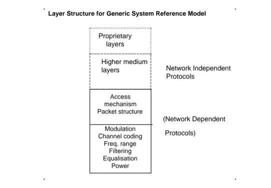
A simplified model of the OSI layers was adopted to facilitate the production of specifications for these nodes. Figure 2 points out the lower layers of the simplified model and identifies some of the key parameters for the lower two layers. Following the user requirements for interactive services, no attempt will be made to consider higher layers in DVB.
Layer Structure for Generic System Reference Model
Modulation Channel coding Freq. range Filtering Equalisation Power Access mechanism Packet structure Higher medium layers Proprietary layers (Network Dependent Protocols) Network Independent Protocols
Figure 2: Layer structure for generic system reference model
The present document addresses network specific aspects only. The network independent protocols are specified separately in ETS 300 802 12].
4.2
System model
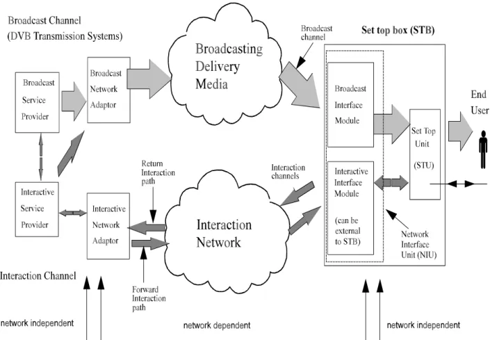
Figure 3 shows the system model which is to be used within DVB for interactive services. In the system model, two channels are established between the service provider and the user:
Broadcast Channel (BC): An unidirectional broadband BC including video, audio and data is established from the
service provider to the users. It may include the Forward Interaction path.
Interaction Channel (IC): A bi-directional IC is established between the service provider and the user for interaction
purposes. It is formed by:
a) Return Interaction path (return channel): From the user to the service provider, the Return Interaction path is frequently used to make requests to the service provider or to answer questions. It is a narrow-band channel, commonly known as return channel.
b) Forward Interaction path: From the service provider to the user, the Forward Interaction path is used to provide some sort of information by the service provider to the user and any other required communication for the interactive service provision. It may be embedded into the BC. It is possible that this channel is not required in some simple implementations which make use of the BC for the carriage of data to the user.
The User Terminal (UT) is formed by the Set Top Unit (STU) and the Network Interface Unit (NIU). The NIU consists of the Broadcast Interface Module (BIM) and the Interactive Interface Module (IIM). The UT provides interface for both broadcast and interaction channels.
The interface between the UT and the interaction network is via the IIM.
4.3
Application of the reference model
This subclause describes the application of the reference model to the SMATV Interaction Channel (IC).
Figure 4 presents the reference model for the particular case of the SMATV IC based on the concatenation of satellite and coaxial sections.
In te ract iv e Net w or k Ad apt er NIU Network Interface Unit
Interactive Service Provider Transmission Network Independent Interaction Media Interaction channel Return Interaction path Forward Interaction path In te ract iv e In te rf ace M o du le SET TOP UNIT B ro ad ca st N etw o rk A d ap te r Broadcast Service Provider
Broadcasting delivery media
Satellite DVB-S CATV DVB-C SMATV DVB-SMATV Terrestrial DVB-T MMDS DVB-MS Broadcast channel Broadcast channel Broa dc as t I n te rf ace Mod u le USER TERMINAL (STB) Transmission Network Independent
Ay
Ax
Ab
Aa
Satellite
Section
Coaxial
Section
Aw
SMATV Interaction Channel based on Satellite & Coaxial sections
Figure 4: Reference model for the particular case of SMATV Interaction Channel
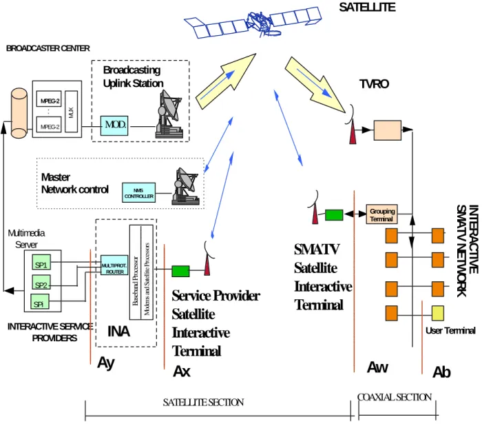
The block diagram for system implementation is presented in figure 5 in order to show the correlation with the reference model.
INTERACTIVE SERVICE PROVIDERS
IN
T
E
RAC
T
IV
E
SM
A
T
V N
E
T
W
O
R
K
Multimedia Server SP1 Grouping Terminal SPi MULTIPROT. ROUTERAy
User TerminalTVRO
Ax
Aw
Ab
SP2 B as eba nd P roc es so r M od em s a nd S at el li te P ro cesso rsSATELLITE
SATELLITE SECTION COAXIAL SECTION
SMATV
Satellite
Interactive
Terminal
Service Provider
Satellite
Interactive
Terminal
NMS CONTROLLERMaster
Network control
INA
BROADCASTER CENTERBroadcasting
Uplink Station
MOD. MPEG-2 MPEG-2 MPEG-2 MU X5
IC for SMATV systems based on satellite and coaxial
sections
This clause provides a system description of DVB IC for SMATV systems based on satellite and coaxial sections. The SMATV infrastructures can support the implementation of the IC for interactive services suitable for DVB systems. Therefore, SMATV systems can be used to implement interactive services in the DVB environment, providing a bi-directional communication path between the User Terminal (UT) and the service provider.
The DVB does not intend to specify a return channel solution associated to each broadcast system because the interoperability of different delivery media to transport the return channel is desirable. The solutions here provided for IC for SMATV systems based on satellite and coaxial sections are a part of a wider set of alternatives to implement interactive services for DVB systems.
The Interaction Channel (IC) is made up by two sections, satellite and coaxial, as depicted in figure 1. For the Return Interaction path (upstream), the interactive traffic from the users is transmitted in the lower part of the frequency band of the bi-directional (passive) coaxial distribution network and is collected at the SMATV head-end by the Grouping Terminal (GT), then it is transported to the service provider through the SMATV Satellite Interactive Terminal (SIT). For the Forward Interaction path (downstream) the responses from the service provider are distributed through the bi-directional satellite network to the SIT at the SMATV head-ends and then, inside each building, the distribution is performed through the GT to each user using the lower part of the frequency band of the bi-directional (passive) coaxial distribution network.
Alternatively, or in parallel, the Forward Interaction path (downstream) could be embedded into the BC in the MPEG-2 Multiplex, when required by the capacity in the Forward Interaction path or the type of application.
The BC is transmitted as specified by EN 300 473 [1] (DVB-SMATV).
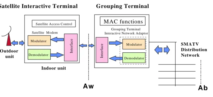
Figure 6 presents the functional block diagram of the SMATV IC system for both: a) the whole SMATV Interactive Head-end, composed by the SIT and the GT, and b) the SMATV Interactive User Terminal (IUT).
Grouping Terminal Interactive Network Adaptor
MAC functions
In te rfa c e Modulator Demodulator SM ATV Distribution NetworkGrouping Terminal
Satellite Interactive Terminal
In te rfa c e Modulator Demodulator
Satellite Access Control Satellite Modem
Indoor unit Outdoor
unit
Aw
Ab
SM ATV Interactive Head-end
Modulator Demodulator Interactive Interface Module Broadcast Interface Module
Set
Top
Unit
Aa
SMATV Interactive User Terminal
(Set Top Box)
SMATV
Distribution
Network
Ab
NIU
User Terminal
Figure 6b: Functional block diagram for the DVB SMATV Interactive User Terminal (IUT)
5.1
Satellite section
The satellite section for the SMATV interactive system is based on satellite networks, using very cost effective solutions designed and matched to the SMATV scenario. Also already operating satellite networks which are currently installed in a number of buildings can be reused for interactive Multimedia applications.
In the present document references are provided to bi-directional SMATV Satellite Interactive Terminals (SIT) working in the Ku band (14/11-12 GHz), although it is recognized that other systems are being developed in Ka band oriented to Direct-To-Home (DTH) applications without precluding its use in a SMATV scenario.
The type of satellite network here considered consists of a central earth station, usually called the Master Station (which provides the management of the satellite network) and a number of remote earth stations (the SIT). Service providers could be connected either to the Master Station or to any of the remote earth stations depending on the specific network architecture. From the service point of view it means that three types of stations are identified: the Master Station for management of the satellite network, the SIT at the service providers and the SIT at the users. Usually the Master Station and the SIT at the service provider will constitute together the Hub station.
Implementation examples of the satellite section are given in clause 6 for the scenarios identified in clause 1 and for different satellite network technologies such as CDMA (Code Division Multiple Access) and TDMA (Time Division Multiple Access) in order to show the feasibility to implement open and inter-operable systems based on existing standards. With the aim of providing purely illustrative implementation examples, specific sizing exercises are presented matched to hypothetical services and traffic scenarios; deriving in this way antenna sizes, power required, possible configurations, etc.
The key factors defining the satellite section are:
a) The satellite multiple access technology and access control, that will determine the complexity of the terminals as well as the network efficiency in terms of throughput. The optimum satellite access technology and access control type will mainly depend on the type of applications, the type of interaction traffic and the population the network is serving.
b) The antenna size and power amplifier size, which will mostly influence to the cost of the SIT and its operational flexibility, as well as the frequency band used for the IC.
c) The network management capabilities that should allow a robust system with a minimum signalling traffic load (see annex B).
5.1.1
Satellite multiple access technology and access control
The system should be prepared for several types of applications which could be typically used at different hours during the day, as for example:
a) Massive avalanche traffic of very short user responses produced as a reaction to a broadcasted program in the broadcasting "Prime time" during the evenings.
b) Other Multimedia applications requiring higher bandwidth such as teleworking, Internet access, etc., which are usually used during throughout all day time.
Different satellite multiple access technologies can be used. Clause 6 provides examples for CDMA / TDMA systems. CDMA means that several channels are provided in the same frequency slots with orthogonal codes. TDMA means that the carrier is split in time bursts.
The following satellite access control modes are commonly used:
1) contention mode as for example in Slotted Aloha or Pure Aloha modes;
2) fixed assignment, for example specific time slots for each terminal in a TDMA mode; 3) reservation mode;
4) dynamic assignment (bandwidth on demand); 5) polling type modes;
6) other mixed possibilities.
Some qualitative assessments on the applicability of each access mode are provided below.
Contention modes are very flexible because when there is a low traffic and it is spread over time the number of collisions is rather small and both delay and throughput are satisfactory. These modes provide the advantage that when the total traffic load is low the whole capacity of each carrier can be used by a single user.
The Slotted Aloha mode establishes reference time slots when a packet can be sent. This makes the access mode more efficient than the Pure Aloha mode in case the network is highly loaded, reaching a theoretical throughput of about 37% at maximum load of the nominal carrier capacity.
Fixed assignments are efficient for applications producing nearly constant or at least predictable traffic generated by each building (or group of buildings). There are no additional delays caused by retransmission, but delays may be caused when the packet to be sent is longer than the assigned burst in the TDMA frame. Nevertheless, the bandwidth efficiency could be low because most of the time there may be unused slots.
Reservation mode is a kind of fixed assignment controlled dynamically depending on the request from the terminals to reserve certain number of slots to transmit a specific amount of information. It prevents the network to be saturated with collisions when a batch traffic is produced by any terminal.
Dynamic assignment is a kind of fixed assignment controlled dynamically depending on the request from the terminals to reserve certain number of slots per time unit in order to allow a certain bit rate for a specific building or group of buildings. It does not seem an adequate solution for transactional traffic formed by short messages although it could be a very convenient approach for an scenario in evolution towards wideband Multimedia applications.
Polling type modes could be inefficient for big networks with several thousands of terminals as it is foreseen in the DVB scenario.
Mixed modes which take the advantage of fixed assignment, reservation, dynamic assignment and contention based modes are available in existing and planned systems and therefore any type of combination of access control modes can
be implemented. Clause 6 provides examples of Slotted Aloha in CDMA and fixed assignment in TDMA mode, as well as TDMA with Slotted Aloha at a higher bit rate, which is oriented towards a scenario supporting Multimedia
applications.
The conceptual Interaction Channel (IC) solution described in the present document allows the implementation of any of the above access modes provided the interface requirements with the coaxial section are met.
5.1.2
Antenna size and power amplifier
In order to establish adequate satellite link margins, the SIT should be sized to produce the adequate Equivalent Isotropically Radiated Power (EIRP) level which can be achieved by trading-off the antenna gain (equivalent to antenna size) and the power amplifier. Based on an example of link budget performed with representative examples of
HISPASAT satellite parameters and taking as an example a data rate of 16 kbit/s (see annex A for examples of link budgets) a combination of 90-120 cm antennas with 0,1 0,2 W amplifiers is a good compromise between cost and performance for most cases depending on the specific satellite coverage, system performances, service availability, etc. It is understood, in consultation with manufacturers, that in order to achieve a low cost power amplifier avoiding the need of thermal radiators, the maximum power should be less than 0,5 W at the SIT. The antenna size is not a critical requirement in the SMATV environment, because just one antenna is needed for the whole building (o group of buildings) to be installed on the roof and because the final cost of the terminal, in practice, does not depend of the antenna size, provided it is smaller than 1,2 m.
On the other hand, the off-axis EIRP of each carrier (in CDMA it means the addition of the EIRP of several carriers with the same frequency slot and orthogonal codes) should be compliant with the relevant criteria for protection between satellite systems (see note) avoiding harmful interference.
NOTE: See in annex B the off-axis EIRP emission density considered.
Therefore, in the trade-off between antenna size and power amplifier, the off-axis EIRP criterion should be considered. This requirement can be met with current antenna technology even assuming a 55 cm antenna and an up to 0,7 W amplifier (for the case of 16 kbit/s, see annex B), although both criteria, cost requirements and the link margin, recommend bigger antenna (90-120 cm) sizes and smaller amplifiers (0,1-0,2 W).
Here again, a trade-off between antenna size, power amplifier and satellite transponder parameters should be made by the operator matching the specific service requirements.
5.2
Coaxial section
The coaxial section supports the bi-directional communications between the User Terminal (UT) and the Grouping Terminal (GT). The Interaction Channel (IC) is based on the same SMATV coaxial distribution network than the Broadcast Channel (BC) but using the lower frequency range (15-35 MHz). The Interactive Interface Module (IIM), which is located at the user side, provides the performance required for signal transmission (modulation, demodulation, channel coding, network access, etc.) through its interface and channel adapter called IIM (see figure 7). The GT at the SMATV head-end collects/distributes the interaction traffic related to the users connected to one or more independent SMATV networks in order to feed the SIT.
SMATV
Distribution
Network
Aw
SMATV Coaxial section
S a te llite S ectio n
Aa
Ab
Modulator Demodulator Interactive Interface Module Broadcast Interface ModuleSet
Top
Unit
NIU
Grouping TerminalInteractive Network Adaptor
MAC functions
In terfac e Modulator DemodulatorGrouping Terminal
User Terminal
Figure 7: Block diagram of the SMATV coaxial section
For the coaxial section the baseline recommended solution consists on a subset of the options provided by the
DVB-RC-CATV specification (see ETS 300 800 [9]) allowing a system simpler than the CATV one, thus matching the requirements of the SMATV scenario. One of the key elements of the SMATV scenario with respect to the CATV one is that the Grouping Terminal (GT) at the SMATV head-end is an equipment of a consumer type in a similar way as the STB, although the SMATV head-end cost is shared among the users connected to the SMATV, which could be those of a single building or a group of buildings.
Due to the specific cost requirements of the SMATV, and taking into account the reduced number of users in SMATV (typically 5 to 300 users) in comparison with typical CATV networks, an appropriate subset of the DVB-RC-CATV system options is recommended in order to minimize the complexity and the cost of the GT.
In principle, it is intended that the SMATV IIM at the UT should be identical to the one needed for CATV system taking advantage in this way, for both scenarios CATV and SMATV, of the economies of scale of the IIM at the UT. In summary, the IIM at the UT will be the same, either for SMATV users or CATV users, but the GT at the SMATV interactive head-end will be much simpler than the CATV interactive head-end.
A description on the coaxial section system concept follows. SMATV coaxial section solution is based on the DVB-RC-CATV system. Therefore, the full detailed description of the physical layer parameters, access modes, MAC functions, etc., are provided in ETS 300 800 [9].
The coaxial section allows the transmission of IC signals through the Forward Interaction path (downstream) and Return Interaction path (upstream). The general concept is to use the Forward Interaction path from the GT to the IIM to provide synchronization and information to all IIM. This allows the IIM to adapt to the network and send synchronized information in the Return Interaction path. Return Interaction path carriers are divided into time slots which can be used by different users, using the TDMA technique. One Forward Interaction carrier is used to synchronize up to 8 Return Interaction path carriers, which are all divided into time slots. A counter at the GT is sent periodically to the IIM, so that all IIM in the same SMATV network work with the same clock. This gives the opportunity to the GT to assign time slots to different users.
Three major access modes are provided with this system. The first one is based on contention access, which lets users sending information at any time with the risk to have a collision with other user's transmissions. The second and third modes are contention-less based, where the GT either provides a finite amount of slots to a specific IIM, or a given bit rate requested by a IIM until the GT stops the connection on IIM's demand.
These access modes are dynamically shared among time slots, which allow IIM to know when contention based transmission is allowed or not . Periodically, the GT will indicate to new users that they have the possibility to go through sign-on procedure, in order to give them the opportunity to synchronize their clock to the network clock, without risking collisions with already active users. This is done by leaving a larger time interval for new users to send their information, taking into account the propagation time required from the GT to the IIM and back.
Several simplifications of the head-end as specified for the CATV system (DVB-RC-CATV; see ETS 300 800 [9]) can be applied to the SMATV scenario in order to allow for a simple GT with a lower processing capability.
These simplifications can be done for the SMATV systems because the lower number of users and the smaller distance that separates the head-end and the users with respect to the CATV networks. In any case the Integrated Receiver Decoder (IRD) based on DVB-RC-CATV (ETS 300 800 [9]) would apply for SMATV taking advantage on the expected economy of scale. The options recommended for the SMATV scenario in ETS 300 800 [9] are:
1) Use the Out Of Band (OOB) option with a unique carrier in each direction. Alternatively, or in parallel, the Forward Interaction path could be embedded into the BC in the MPEG-2 Multiplex, when the capacity required in the downstream or the type of applications require it.
2) Use of a single 3,088 Mbit/s carrier for the Return Interaction path to be shared among the number of users in the SMATV network.
3) Use of a single 3,088 Mbit/s carrier for the Forward Interaction path to be shared among the number of users in the SMATV network.
4) Reduced frequency ranges (15-35 MHz).
5) No power or timing ranging (simplified MAC protocol).
6) In some cases, fixed rate assignment to each user could be used in accordance to the total capacity assigned to the satellite section.
When the IIM is external to the UT, the interfaces defined by DVB for the IRD should be used (EN 50201 [24]).
5.2.1
Spectrum allocation
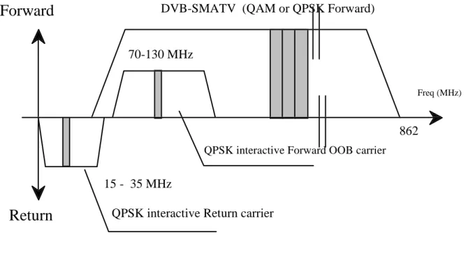
Figure 8 indicates a possible spectrum allocation. Although not mandatory, a guideline is provided to use the following preferred frequency ranges:
70-130 MHz for the Forward Interaction path (downstream OOB); and
15-3 MHz for the Return Interaction path (upstream), or parts thereof.
The use of limited frequency ranges simplifies the tuner complexity (filtering) and does not mean any capacity constrain provided a recommendation is done to use just one carrier for Forward Interaction Path and another for Return
QPSK interactive Forward OOB carrier
Freq (MHz)
Forward
Return
QPSK interactive Return carrier
862
DVB-SMATV (QAM or QPSK Forward)
70-130 MHz
15 - 35 MHz
Figure 8: DVB preferred frequency ranges for SMATV interactive systems
5.2.2
FDM/TDMA multiple access
A multiple access scheme is defined in order to allow different users sharing the same transmission media. Forward information is sent broadcast to all users of the networks. Thus, an address assignment exists for each user which allows the GT to send information single-cast to one particular user. Two addresses are stored in the STB in order to identify users on the network:
1) MAC address which is a 48-bit value representing the unique MAC address of the NIU. This MAC address may be hard coded in the NIU or be provided by external source. 2) NSAP address which is a 160-bit value representing a network address.
This address is provided by higher layers during communication.
Return information may come from any user in the network and therefore shall be also differentiated at the GT using the set of addresses defined above. Each Forward Interaction path carrier contains a synchronization frame used by up to 8 different Return Interaction path carriers, whose frequencies are indicated by the Media Access Control (MAC) protocol. In any case, for most cases one carrier for Return Interaction path and another for Forward Interaction path is enough for providing the capacity required by most SMATV systems.
Within Return Interaction path carriers, users send packets with TDMA type access. This means that each channel is shared by many different users, who can either send packets with a possibility of collisions when this is allowed by the GT, or request transmission and use the packets assigned by the GT to each user specifically. Assuming each channel can therefore accommodate up to thousands of users at the same time, the Return bandwidth can easily be used by all users present on the SMATV network at the same time (as a reference the typical number of users in SMATV networks could vary from 5 to 300 users).
The TDMA technique utilizes a slotting methodology which allows the transmit start times to be synchronized to a common clock source. Synchronizing the start times increases message throughput of the signalling channel since the message packets do not overlap during transmission. The period between sequential start times are identified as slots. Each slot is a point in time when a message packet can be transmitted over the signalling link.
The time reference for slot location is received via the Forward Interaction path carrier generated at the GT and received simultaneously by all IIM attached to the SMATV network.
Since the TDMA signalling link is used by IIM that are engaged in interactive sessions, the number of available message slots in this channel is dependent on the number of simultaneous users. When messaging slots are not in use, an IIM may be assigned multiple message slots for increased messaging throughput. Additional slot assignments are provided to the IIM from the downstream signalling information flow.
There are different access modes for the Return Interaction path slots:
a) reserved slots with fixed rate reservation (Fixed rate Access: the user has a reservation of one or several time slots in each frame enabling, e.g. for voice or audio);
b) reserved slots with dynamic reservation (Reservation Access: the user sends control information announcing his demand for transmission capacity. He gets grants for the use of slots);
c) contention based slots (these slots are accessible for every user. Collision is possible and solved by a contention resolution protocol);
d) ranging slots (these slots are used Return Interaction path to measure and adjust the time delay and the power). These slots may be mixed on a single carrier to enable different services on one carrier only. If one carrier is assigned to one specific service, only those slot types will be used which are needed for this service. Therefore, a terminal can be simplified to respond to only those slot types assigned to the service.
5.2.3
Bit rates and framing
For the Forward Interaction path in SMATV, a rate of 3,088 Mbit/s is recommended in consistency with the appropriate bit rate for other alternative transmission media to the satellite section (as for example Local Multipoint Distribution System - LMDS).
The Forward Interaction path carrier continuously transmit a frame based on T1 type framing, in which some information is provided for synchronization of Return Interaction path slots.
For the Return Interaction path, the GT can indicate the transmission rate to users, specifically 3,088 Mbit/s is recommended for SMATV following the same rationale as for the Forward Interaction path.
Figures 9 and 10 show the conceptual block diagrams for implementation of the coaxial section.
SMATV NIU
Grouping Terminal at the SMATV Head-end
Figure 10: Conceptual block diagram for the OOB head-end transceiver
5.3
Satellite-coax interface
In order to allow an open and inter-operable system a specification for the interface between the satellite and coaxial sections is given. The complete definition of this interface allows for the use of alternative technologies for both the satellite and coaxial sections with the aim to facilitate the interoperability between subsystems from different vendors and technologies.
The definition of this interface also allows the reuse of the coaxial section for establishing the IC through different transmission media alternative to the satellite.
A very low cost interface, RS-232 based, is the baseline recommended solution although alternative interfaces are identified in order to allow the reuse of existing satellite terminals as SIT.
5.3.1
RS-232 serial interface
5.3.1.1
Mechanical and electrical characteristics.
The interface will comply with EIA 232-D [25], more specifically: ⇒ logical: ITU-T Recommendation V.24 [16];
⇒ electrical: ITU-T Recommendation V.28 [17]; ⇒ mechanical: ISO 2110 [19] standard (25-pin connector); working with the following basic parameters:
a) speed: configurable up to 119 200 bit/s b) data bit;
c) no parity;
The coax section will act as Data Terminal Equipment (DTE), and so its connector will have male contacts (female shell). The SIT will play the role of Data Communications Equipment (DCE), so its connector will have female contacts (male shell).
5.3.1.2
Framing
The Maximum Transfer Unit (MTU) is defined as 1 024 bytes (see note) for this interface. This means, that any data packet longer than the MTU defined, should be segmented before transmission through this interface.
NOTE: The size of 1 024 bytes for the MTU has been chosen, because it is an adequate value to be used with the SLIP protocol which can be implemented for this interface.
5.3.1.3
Flow control mechanisms
Flow control may be implemented using the Clear To Send/Request To Send (CTS/RTS) signals (hardware flow control) or the XON/XOFF protocol (software flow control).
Data flow from the coax section towards the satellite section will be limited according to the following rules, when using the CTS/RTS flow mechanism:
1) The coax section equipment will make sure the CTS signal is LOW before starting transmission of a new data packet.
2) The SIT will set CTS LOW as soon as free space in its internal buffers allows for a whole maximum-size data packet . CTS will be set back HIGH when there is space for a new packet.
3) It is up to the SIT implementers to choose when the CTS signal shall be set HIGH as buffers are emptied. It is the responsibility of the SIT equipment to ensure that no data is lost as long as the coax section complies with the first rule.
4) The coax section shall propagate data flow limitations towards the user equipment to avoid packet losses. Data flow towards the coax section has no flow mechanism.
5.3.2
Alternative interfaces
5.3.2.1
LAN based interfaces
In order to facilitate the evolution towards Multimedia broadband applications, alternative interfaces based on Local Area Networks (LAN) technology are identified in order to provide solutions to the potential barriers that the RS-232 may present in terms of maximum bit rate. For this purpose a typical Ethernet interface is proposed, which is very extended and facilitates the interconnections to LAN for any other kind of needs.
For the mechanical and electrical characteristics the interface shall comply with EIA 568-A [21], i.e. it shall be an IEEE 10 Base-T Ethernet (IEEE 802-3 [20]) with RJ-45 connectors. With respect to the framing and error control a standard for framing of data packets into Ethernet is described in IEEE 802-3 [20].
5.3.2.2
X.25 communications interfaces
Most of the existing satellite networks (VSAT type) implement in their terminals the protocols and physical interfaces used for X.25 communications (see ITU-T Recommendation X.25 [18]). Therefore these kind of connections might have to be considered when reusing already operating satellite networks which are currently installed in a number of buildings. Interfaces for the interconnection of VSAT systems to Packet Switched Public Data Networks (PSPDN) are described in ETS 300 194 [7].
6
Implementation examples for the satellite section
This clause provides implementation examples based on existing satellite network systems, with the aim of illustrating the flexibility of the satellite section for the IC in SMATV.
Examples are provided for the two kind of scenarios described in clause 1: a) asymmetric services for interactive broadcasting applications;
b) Multimedia wide-band services.
6.1
Asymmetric services scenario for interactive broadcasting
applications
For asymmetric services in interactive broadcasting applications a reference traffic model has been considered (see DIGISAT Project [22], [23]). Two examples of traffic patterns generated by the users for the Return Interaction path are considered:
1) Transactional traffic which is characterized as an average of 2 messages-per-minute-per-active-user at the loaded hour. The average message length is considered to be of 281 bytes, which means an average traffic per user of about 75 bit/s. This traffic model is applied to transactional applications such as teleshoping, financial transactions, request for information, etc. For most applications in this category (transactional interactive applications) the traffic generated for the Forward Interaction path is symmetric with respect to the one at the Return Interaction path. An average user activity factor of about 10% of simultaneous active users transmitting in the same instant is considered. It means that, considering an average of 20 users per SMATV system, the average traffic per building could be evaluated in about 150 bit/s.
2) Avalanche traffic as a response to a broadcast service which is characterized by the generation of a single message from each user in a near simultaneous way. The message size for this case is evaluated as 53 bytes, which considering an average of 20 users per SMATV grouping generating avalanche traffic, it would mean an average traffic load of 8 480 bits per building or group of buildings in case of avalanche. A randomization mechanism can be used in this case in order to spread the time interval in which the avalanche is produced (see ETS 300 802 [12]). This traffic model is applied to user responses to broadcast material in an anonymous manner, for instance voting or opinion polling, etc.
For the satellite section, two implementation examples are hereafter presented, one based on TDMA, which uses fixed assignment access, and the other based on CDMA, which uses the Slotted Aloha contention access protocol.
6.1.1
Example based on TDMA with fixed assignment
In TDMA the satellite carrier is organized in periodic frames which are assigned to a SIT for a short period of time. It means that a SIT uses the whole bandwidth of the carrier during the assigned time slots without colliding with transmissions from other terminals.
The space segment is usually organized in FDMA carriers for the or Return Interaction path (also known as inbound carriers or upstream), using a TDMA access scheme, that means that each Return Interaction carrier (inbound) is generated by different SITs at different time slots.
The example provided to illustrate a certain configuration for the proposed traffic model is based on the following parameters:
a) Return Interaction path (inbound) carriers of 16 kbit/s, working in a TDMA mode, QPSK modulated with FEC 1/2 occupying about 40 kHz each.
b) Forward Interaction path (outbound) carriers of 16 kbit/s, working in a TDM mode, QPSK modulated with FEC 1/2 occupying about 40 kHz each. Up to 32 inbound carriers are configured per each outbound carrier.
c) Each carrier is configured into 40 time slots of 53 bytes each. Each time slot is assigned to one SIT, providing a constant gross capacity of 400 bit/s for each SIT. Considering headers occupying about 10% of the capacity, the constant useful bit rate for each SIT is about 360 bit/s which is about twice the average transactional expected traffic.
d) In the 2 MHz bandwidth, up to 50 carriers can be allocated, which means to provide a constant "low" capacity to 2 000 SIT.
Figure 11 represents the space segment use for this scenario.
...
50 Inbound C arriers in 2 M H z
40 K H z each carrier
O utbound C arriers
40 K H z each carrier
T D M A Space Segm ent U sage
Each inbound carrier
is accessed by 40
different term inals
Figure 11: Example based on TDMA with fixed assignment
Link budget examples are presented in annex A for different combinations of Hub (within the present document Hub terminology refers to the SIT at the service provider which may include the Master station) and SIT antenna diameters. As an example SIT of 90 cm require less than 70 mW for operating with a 2,4 m Hub antenna. This configuration is compliant with the off-axis EIRP as recommended in the present document with a margin of about 15 dB, provided that typical 90 cm antennas can work with up to 2,3 W (see annex B).
6.1.2
Example based on CDMA with Slotted Aloha
By using CDMA the information signal is spread into a wide bandwidth using spread spectrum techniques. The codes used for this purpose have orthogonal characteristics allowing any individual code to be distinguished from others, which permits several signals with orthogonal codes to share a common frequency band. The maximum number of signals that can share the same slot depends mainly on the maximum number of different CDMA codes (it depends on the code length).
The space segment available is organized into frequency slots and CDMA codes. A certain number of slots are reserved for the Return Interaction path (inbound communications from SIT to the Hub) and some others for the Forward Interaction path (outbound communications from the Hub to SIT). Each SIT is provided with a frequency slot and a specific code. Several terminals can share frequency slots and code when accessing to the satellite in a Slotted Aloha mode. Outbound carriers work in a TDM mode.
The example provided to illustrate a certain configuration for the proposed traffic model is based on the following parameters:
a) Return Interaction path (inbound) carriers of 16 kbit/s, working in a CDMA mode, QPSK modulated with FEC 3/4 and spread with a chip frequency of 1,45 Mchip, occupying about 2 MHz per frequency slot. Inbound carriers work in a Slotted Aloha mode.
b) Forward Interaction path (outbound) carriers of 16 kbit/s, working in a CDM continuous mode, QPSK modulated with FEC 3/4 and spread with a chip frequency of 1,45 Mchip, occupying about 2 MHz per frequency slot. c) The maximum number of carriers per frequency slot is 127 coinciding with the number of different possible
orthogonal codes.
d) Each carrier provides a maximum instantaneous bit rate of 16 kbit/s. Considering headers as about 10% of the capacity, the constant useful bit rate that each CDMA channel (each pair frequency slot and code) can process is about 14,4 kbit/s. Although for maximum load the Slotted Aloha mode can offer a theoretical throughput of 37% of the nominal capacity due to collisions, a throughput of about 20% is considered for a reasonable average delay. It means that in order to provide the average traffic of 150 bit/s per SIT, each CDMA channel (the pair frequency slot/CDMA code) can be allocated to 19 SIT for sharing such CDMA channel.
In 2 MHz bandwidth, 127 codes can share each frequency slot allowing up to 2 413 SIT working in that bandwidth. Figure 12 represents the space segment usage for this particular scenario.
S l o t 1 ( 2 M H z )
S l o t n
S l o t n + 1
. . . .
I n b o u n d S l o t s O u t b o u n d S l o t s c o d e 1 c o d e 1 2 7 c o d e 1 c o d e 1 2 7 c o d e 1 c o d e 1 2 7S p a c e S e g m e n t U s a g e
Figure 12: Example based on CDMA with Slotted Aloha
Link budget examples are presented in annex A for different combinations of Hub and SIT antenna diameters. As an example SIT of 90 cm require less than 100 mW (for 16 kbit/s carriers) for operating with 2,4 m Hub antenna. This configuration allows up to 1 311 terminals transmitting simultaneously on the same frequency slot for compliance with the off-axis EIRP as recommended in the present document (see annex B). It means that off-axis EIRP criteria is met even in the case of instantaneous multiple collision originated by 1 311 SIT. The use of a randomization mechanism to spread the time interval in which the avalanche is produced minimize the probability of a high number of