415
©IJRASET: All Rights are Reserved
Implementation and Control of IoT based Home
Robotixation using Arduino
P. Mercy 1, N. Asaikaviamuthan 2, G. Monisha3, R. Surya4 1
Assistant professor, Department of EEE, INFO Institute of Engineering, Tamilnadu, INDIA 2, 3, 4
UG Student, Department of EEE, INFO Institute of Engineering, Tamilnadu, INDIA
Abstract: Internet of Things allows us to control connected devices from anywhere and exchange data over the devices. Home automation system controls home appliances automatically and when this system is connected to internet it becomes a part of IoT. There are three main generations of home automation. First is, different wireless technology with proxy servers, second is Artificial Intelligence (AI) controlled home automation and lastly robots which directly communicate with humans. Our project is first generation automation. For implementing the first generation of the home automation appliances needs to connect with internet so users can control the system from any remote place. That’s why IoT has become a need for automation. A home automation system may control lights, temperature, climate, entertainment and many other appliances. Home security is also a part of automation which includes security control and alarm system. The control system could be wall mounted, computers, a mobile phone application or web interface. . In our proposed system we have used web page based control system. The home automation market was worth US$5.77 billion in 2013, predicted to reach a market value of US$12.81 billion by the year 2020.Our paper Sensing and controlling the world around using Arduino and IoT deals with embedded technologies along with internet of things (IoT) using Arduino which employees the embedded block and script programming for Arduino and WI-FI module.
Keywords: Home Automation, Arduino, Internet of things (IoT), Think Speak, Wireless communication.
I. INTRODUCTION
The world has changed after the evolution of term called Automation. In every sector automation is reducing human labour. Firstly introduced in industries and now in a variety of sectors rely on automation system. Development of advanced home automation system has huge opportunity in present time. Again Internet of Things (IoT) is going to be a new era of technology in future. It is expected that 30 billion of devices will be connected within 2020. So it is the right to get prepared for the future technologies. The Internet of things (IoT) is the nerwork of devices such as vehicles and home appliances. That contain electronics, software, actuators and connectivity which allows these things to connect , intract and exchange data. Arduino is an open-source hardware and software company, project and interactive objects that can sense and control objects in the physical and digital world. The IoT has created the revolution all over the world and fascinatingly it become a fascinatingly it has become integral part of life. Home automation using IoT, is an application that provides safety, comfort, and above all, self – allows energy consumption to be monitored and keep track of all activities happening inside the house. Home automation refers to remotely monitoring the conditions of home and performing the required actuation. Through home automation ,household devices such as TV, Light bulb, Fan ,etc. are assigned a unique address and are connected through a common home gateway. These can be remotely accessed and controlled from any PC, mobile or laptop. This can reduce energy wastage and improve the living conditions besides enhancing the indoor security.
II. SYSTEMDESIGN
Home automation system design gives an idea about the operation of home automation system. The four different appliances such as fan, light, room heater and TV are operated remotely using Wi-Fi and through an application installed on android or iPhone. These appliances are connected through Arduino Uno with its digital input/output pins. These devices are connected with local Wi-Fi using a communicating module called esp8266-01.
III. SIMULATION
A. Arduino UNO
416
©IJRASET: All Rights are Reserved
Fig.1 Arduino uno
B. Relay
Channel relay is connected to the Arduino Uno and its output is connected to the home appliances in a sequence as (i) fan (ii) light (iii) room-heater and (iv) TV set. Relay takes low current and voltage and triggers the switch which is connected to a high voltage. 4 input pins of relay are connected to Arduino which takes5V supply from it and can trigger up to 10A, 250V supply
Fig.2 Relay
C. ESP8266-01
The ESP8266-01 is a highly compact board, used as a peripheral for any board through serial (RX/TX) and also as a standalone board. The board requires 3.3 V and can be programmed with any FTDI operating at 3.3 V. The pins include power (+3.3 V and GROUND), RX / TX, CH_PD to enable the chip and 2 General Purpose Input Outputn (GPIO) [14].
Fig.3 Node MCU(ESP8266 )
D. WIFI
Wi-Fi(wireless fidelity) is a wireless communication technology which is used here to provide a hotspot through which ESP8266-01 module can connect. The router will assign a unique IP address to the module for establishing a connection between smart phone and ESP8266-01.
E. Gas Sensor
Gas sensor module detects various types of gas in an area. Here the change in value of resistance is used to calculate the gas concentration. Gases like Methane, Propane, ibutane, Alcohol, Smoke, LPG and also hydrogen can be detected using this module. There are 2 output pins (digital one and analog one).
417
©IJRASET: All Rights are Reserved
F. Temperature Sensor
[image:3.612.156.456.161.358.2]It can measure temperature as well as humidity present in a room. Its range is less than 20 meters. It has a negative temperature coefficient (NTC) element and a humidity-sensitive element which is used to measure temperature between 0-50 degree Celsius.
Fig.5 Temperature Sensor
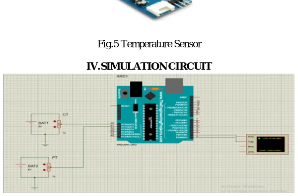
IV. SIMULATIONCIRCUIT
Fig .6 Simulation Circuit
A. Discription
1) In this simulation circuit Arduino, current transformer, voltage transformer, sources are present.
2) The supply was given to the load that load can be consume the voltage and current.
3) Voltage and current values are measured by using current and potential transformer.
4) This current and voltage values are converted into a analoge values A0,A1 are given to the arduino board.
5) Arduino was programmed for to display the output.
V. SIMULATIONPROGRAM
A. Arduino IDE Program
// include the library code: float val=0;
float val1=0; void setup(){ Serial.begin(9600); }
void loop() {
val=analogRead(A0); val=val*100;
Serial.print("CT: "); Serial.println(val/5283.0); delay(200);
val1=analogRead(A1); val1=val1*100; Serial.print("PT: "); Serial.println(val1/1000.0); delay(200);
418
©IJRASET: All Rights are Reserved
B. Discription
Proteus is a simulation base software. By using this software Arduino can be simulation.Figure:2 shows Arduino IDE program
1) Step 1: Arduino IDE Setup Before start simulation need to make sure that in File>>Preferences, compilation is marked. Because "compilation" compile the code and generate .hex file. This .hex file is needed for running the Proteus simulation.
2) Step 2: Proteus Setup: Proteus is the software where we run our simulation. First make sure that have Proteus installed in operating system. If not, then download and install Proteus. After run the Proteus software, If you don't find arduino in the library. Then, there is a .rar file download it and copy/cut the file. After that paste it into the Proteus library. In case the location of the Proteus library is, C drive>Program Files>Lab centerElectronics>Proteus7Professional>LIBRARY. After that we will find arduino in our library.
3) Step 3: (Step-1)Proteus Simulation: Run Arduino IDE and go to File>Examples>01.Basics>Blink and open it. Click on "Verify" button. Then copy the .hex file.
4) Step 4: (Step-2)Proteus Simulation: Run the Proteus and draw the circuit like the picture. Double click on arduino and paste the .hex file in "Program File:".Run the simulation by clicking "Run the simulation" button.
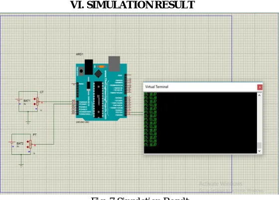
[image:4.612.166.446.271.472.2]VI. SIMULATIONRESULT
Fig .7 Simulation Result
Figure:7 shows the simulation results of the project. The system has both input and output gadgets which have been related to the arduino board for processing the enter gadgets usually accommodates of measuring instruments, signal conditioning units, relays, node mcu and loads. The architecture of the proposed protocols to be used the working of the system and the challenge in the system design are analyzed. So that proposed design can improve the optimization of the system. This enhances security and efficiency of a home which also gives real time monitoring via the internet. It comprises of Arduino controller which gets the input source from node MCU to store the energy readings which is stored in cloud source named think speak, output source requires a relay part for which to control any electrical appliances for this the power supply will be spread through PT to other relay sources for controlling of electrical source to monitor and store digitally. Finally if load to light/ Fan source is heavier than the normally required power it will be automatically stored and required light or fan source will be in OFF state immediately. Switches will be responsible to act based on energy supplied and stored in cloud source either to ON/OFF accordingly for related light or fan source.
VII. APPLICATIONS
1) A home automation system will control lighting, climate, entertainment systems and appliances.
2) Ring video door bell with WiFi camera and Smart surveillance.
3) Automated transportation and Smart energy management system.
419
©IJRASET: All Rights are Reserved
VIII. CONCLUSION
In this smart home system it was manually controlled before for home appliances and automated system, a person should be present to manually monitor the energy source or energy readings. During the period, it will be critical to carry out testing's like security purpose, technology, improvement, consumer education, developments of standards and regulations, information sharing between projects to ensure. So, this smart system will overcome the problems faced before to save energy source.
REFERENCES
[1] Kishore P Jadhav, Santosh G Bari, “Hand Gesture Based Switching Using MATLAB”, IJIREEICE, Vol.4, May 2016. [2] Sharmad Pasha,“ThinkSpeak Based Sensing and Monitoring System For IoT with MATLAB Analysis”, IJNTR, Vol.2, June 2016. [3] Angel Deborah S., “Home Automation Systems - A Study”, IJCA, Vol. 116, April 2015.
[4] J.Chandramohan,R.Nagaraja,K.Satheeshkumar,N.Ajithkum P.A.Gopinath S.Ranjithkumar, “Intelligent Smart Home Automation and Security System Using Arduino and Wi-fi”, IJECS, Vol.6, March 2017.
[5] Surinder Kaur, Rashmi Singh, Neha Khairwal, Pratyk Jain, “HOME AUTOMATION AND SECURITY SYSTEM”,ACII,Vol.3,July2016.
[6] Efficient and Autonomous Energy Management Techniques for the Future Smart Homes- IEEE Transactions on Smart Grid ( Volume: 8 , Issue: 2 , March 2017 )
[7] IoT-based Smart Grid System Design for Smart Home- The 3rd International Conference on Wireless and Telematics2017July27-28,2017,Palembang,Indonesia.
[8] Design of Smart Home Mobile Application with High Security and Automatic Features- 2018 3rd International Conference on Intelligent Green Building and Smart Grid (IGBSG)
[9] D.Sunehra and M.Yeena, “Implementation of interactive home automation systems based on email and Bluetooth technologies.”2015 International Conference on Information Processing(ICIP).