679
©IJRASET: All Rights are Reserved
Implementation of a Keypad Controlled Security
Robot
Theophilus T. Uhimbir1, Joseph M. Mom2, Samuel T. Awuhe 3
1
Master Student, Department of Electrical and Electronics Engineering, University of Agriculture Makurdi, Nigeria
2
Department of Electrical and Electronics Engineering, University of Agriculture Makurdi,Nigeria
3
Department of Electrical and Electronics Engineering, University of Agriculture Makurdi,Nigeria
Abstract: The implementation of the GSM controlled security robotic vehicle is divided in two main parts; the hardware and the software. The hardware part consists of the following components; two microcontrollers (PIC18F2585 and PIC18F4680), DC motors, GSM Modem, graphic liquid crystal display (GLCD), motor driver, passive infrared (PIR) and ultrasonic sensors while the software aspect comprises the MikroC PRO for programming the PIC18F2585 and PIC18F4680 Microcontrollers. The portable system consisting of a keypad, GSM module and GLCD is used by the user to send commands which tend to control the robot. With the GSM module and the keypad, the user or operator of the robot can send command as an SMS to the GSM module interfaced with the microcontroller on the robot. The microcontroller processes this as a command and sends it to the robotic vehicle to proceed in any desired direction. With this system, the robot can be controlled from any location provided there is GSM network. Besides, a PIR sensor is interfaced with the microcontroller to detect human presence where the robot is deployed and hence notify the operator of the robot by sending an SMS which contains the location of the robot.
Keywords: GSM, Ultrasonic sensor, Graphic liquid crystal display, Microcontroller, Robot
I. INTRODUCTION
Robots are programmed to perform specific tasks which in some cases humans cannot do. To increase the use of robots where conditions are not favourable for human performance such as in rescue operations or surveillance areas, robots can be made to follow the instructions of humans to perform certain tasks. In this way decisions are taken by the robots according to the instructions of the operator. Thus, we can use these robots to perform those tasks that may be dangerous for human beings (Jena et al., 2015).
II. REVIEW OF RELATED WORKS
In the work by Ranu and Renuak (2013), a robotic car with infrared TV remote controller was constructed. The car was able to move in all four directions but the IR remote control limits its efficiency as it could not be controlled with an object blocking its line-of-sight from the controller. The robotic car was also not controllable from a far distance.
Bourdillon (2015) on the design and analysis of a GSM/RF based remote controlled robotic car presented a solution to such problem whereby a GSM/RF based remote control system could be used to control a robotic car. The user makes a phone call to the phone attached to the robot which automatically answers the call. During the phone call, the user can control the robotic car with the keys on the phone. Hence the user can control the robotic car from anywhere no matter the distance without interference so far as the robotic car can be seen by the user.
Dharmani (2014) on IR remote controlled car used an IR Remote system to control a robotic car which uses two pulse width modulation (PWM) channels of ATmega8 microcontroller for controlling the speed and direction of the car. Although speed control of the car was made possible, the car was unable to make a turn. Poor range of control and line-of-sight alignment was also a problem. In the work published by Sourangsu (2013) on design and implementation of an unmanned vehicle using a GSM network without microcontroller, he proposed a model to remotely control an unmanned vehicle using DTMF technology without the use of a microcontroller. In this model, a DTMF decoder (MT8870) was used to decode the DTMF signals. The output of the decoder was fed directly to an L293D motor driver IC which drives two DC motors. The vehicle was expected to move in all four directions. The model has the advantage of reduced circuit complexity and manpower to program the microcontroller but the absence of a microcontroller made it nearly impossible for a password protection system, sensors and wireless camera system to be included. Mandakini (2015) on the design and implementation of unmanned ground vehicle using GSM network designed an unmanned vehicle targeted at helping to increase human safety by enabling the human to control the vehicle from remote location. This
paper describes the design and implementation of unmanned vehicle which is controlled or handled by SMS or called with the help of
680
©IJRASET: All Rights are Reserved
Similar works by Gupta et al. (2013) on design and implementation of mobile operated toy car by DTMF and Ranu et al. (2013) on GSM mobile controlled robotic car were able to control a robotic car using DTMF signals with the use of a microcontroller. In these works, the received tone is processed by an ATmega16 microcontroller with the help of DTMF decoder MT8870. The decoder decodes the DTMF signal into its binary equivalent and this is sent to the microcontroller programmed to take a decision for a particular input and outputs its decision to the motor drivers in order to drive the robot forward, backward, left or right. In situations where there is no GSM network, these robots cannot be controlled hence there is need to add an alternative way for controlling the robotic car.
In this work, a GSM based wireless system is used for efficient communication. A portable system consisting of a keypad, GSM module and GLCD is used by the user to send commands which tend to control the robot. With the GSM module and the keypad, the user or operator of the robot sends command as an SMS to the GSM module interfaced with the microcontroller on the robot. The microcontroller processes this as a command and sends it to the robotic vehicle to proceed in any desired direction. With this system, the robot can be controlled from any location provided there is GSM network.
A. Block Diagram of the System
[image:2.612.118.439.326.594.2]The block diagram of the system consists of two main units namely; the unit that sends commands to the robot and the robotic vehicle. The user of the system uses a keypad that interfaces with PIC18F4680 microcontroller. When the user sends command to control the robot, the PIC18F4680 processes the command and sends it to the robot through the GSM module which transmits the command sent by the user to the robot. The robotic vehicle receives the command that is processed by PIC18F2585 microcontroller. With the GPS module, the user can identify the location of the robot. The whole block diagram is shown in Fig. 1.
Fig. 1: Block diagram of keypad controlled robotic vehicle
B. Schematic Diagram of the System
The schematic diagram of the robotic vehicle consists of two parts namely the keypad integrated GSM unit and the robot which comprises the GSM and the GPS modules. There are five switches which form the keypad system. These switches are connected to PIC18F4680 microcontroller through the pull-up resistors. With the pull-up resistors, each digital input pin of the microcontroller will be in HIGH state when the button is not pressed. When a button is pressed, it connects the digital input pin to the ground. The current flows through the resistor to the ground which makes the input pin to be in LOW state. The keypad is connected to PORT A of PIC18F4680 while SIM 900D GSM module is connected to PORT C. The transmit pin, TX of the GSM module is connected to pin 25 whereas the receive pin, RX of the module is connected to pin 26 of the microcontroller.
Power
SUPPLY
PIC18F2585
GPS
GSM
module
Motor
driver
DC
motor
Ultrasonic
sensor unit
Power
Keypad
PIC18F4680
GLCD
681
©IJRASET: All Rights are Reserved
[image:3.612.89.537.145.387.2]The robotic part consists of ultrasonic sensors, GSM and GPS modules. The three ultrasonic sensors are connected to PIC18F2585 microcontroller through PORT A pins while the wheels of the robot interface the microcontroller through the motor driver, L293D on PORT C pins. The GSM module and the GPS module pins are connected to pin 25 and pin 26 on PORT C of the microcontroller. The keypad with GSM unit and the robotic circuit diagrams are shown in Fig. 2 and Fig. 3.
Fig. 2 Schematic diagram of keypad integrated GSM unit
Fig. 3. Schematic diagram of robotic system with GSM and GPS units
C1 C2 X1 OSC1 OSC2 RE3/VPP/MCLR 1 RA0/AN0/CVREF 2 RA1/AN1 3 RA2/AN2/VREF-4 RA3/AN3/VREF+ 5 RA4/T0CKI 6 RA5/AN4/SS/HLVDIN 7 RE0/RD/AN5 8 RE1/W R/AN6/C1OUT 9 RE2/CS/AN7/C2OUT 10 RA7/CLKI/OSC1 13 RA6/CLKO/OSC2 14 RC0/T1OSO/T13CKI 15 RC2/CCP1 17 RC3/SCK/SCL 18 RD0/PSP0/C1IN+ 19 RD1/PSP1/C1IN- 20 RD2/PSP2/C2IN+ 21 RD3/PSP3/C2IN- 22 RD4/PSP4/ECCP1/P1A 27 RD5/PSP5/P1B 28 RD6/PSP6/P1C 29 RD7/PSP7/P1D 30 RC4/SDI/SDA 23 RC5/SDO 24 RC6/TX/CK 25 RC7/RX/DT 26 RB0/INT0/FLT0/AN10 33 RB1/INT1/AN8 34 RB2/INT2/CANTX 35 RB3/CANRX 36 RB4/KBI0/AN9 37 RB5/KBI1/PGM 38 RB6/KBI2/PGC 39 RB7/KBI3/PGD 40 RC1/T1OSI 16 U5 PIC18F4680 D5 D4 D3 D2 D1 D0 UP ENTER DOW N
R1 R2 R3
SIM Card
SIM900D
S2-1041Y-Z097C CE0980 Pow er BTN
ON NEXT STATUS TXD RXD www.TheEngineeringProjects.com GSM1 SIM900D-RED LEFT RIGHT R4 R5 C S 1 1 C S 2 2 G N D 3 V C C 4 V 0 5 R S 6 R /W 7 E 8 D B 0 9 D B 1 1 0 D B 2 1 1 D B 3 1 2 D B 4 1 3 D B 5 1 4 D B 6 1 5 D B 7 1 6 R S T 1 7 -V o u t 1 8 LCD1 AMPIRE128X64 D 1 D 2 D 3 D 4 D 5 D 6 D
7 D0
R
S
T E
R
W RS
C S 2 C S 1 +5V 75 % RV3 5k CS1 CS2 RS RW E RST D6 D7 RE3/VPP/MCLR 1 RA0/AN0/CVREF 2 RA1/AN1 3 RA2/AN2/VREF-4 RA3/AN3/VREF+ 5 RA4/T0CKI 6 RA5/AN4/SS/HLVDIN 7 RE0/RD/AN5 8 RE1/W R/AN6/C1OUT 9 RE2/CS/AN7/C2OUT 10 RA7/CLKI/OSC1 13 RA6/CLKO/OSC2 14 RC0/T1OSO/T13CKI 15 RC2/CCP1 17 RC3/SCK/SCL 18 RD0/PSP0/C1IN+ 19 RD1/PSP1/C1IN- 20 RD2/PSP2/C2IN+ 21 RD3/PSP3/C2IN- 22 RD4/PSP4/ECCP1/P1A 27 RD5/PSP5/P1B 28 RD6/PSP6/P1C 29 RD7/PSP7/P1D 30 RC4/SDI/SDA 23 RC5/SDO 24 RC6/TX/CK 25 RC7/RX/DT 26 RB0/INT0/FLT0/AN10 33 RB1/INT1/AN8 34 RB2/INT2/CANTX 35 RB3/CANRX 36 RB4/KBI0/AN9 37 RB5/KBI1/PGM 38 RB6/KBI2/PGC 39 RB7/KBI3/PGD 40 RC1/T1OSI 16 U1 PIC18F4680 C3 C4 X2 OSC11 OSC12 SIM Card SIM900D S2-1041Y-Z097C CE0980 Pow er BTN
ON NEXT STATUS TXD RXD www.TheEngineeringProjects.com GSM2 SIM900D-RED TXD RXD www.TheEngineeringProjects.com 25V 100uF GPS Module
GPS1 GPS MODULE
IN1
2 OUT1 3
[image:3.612.56.564.409.719.2]682
©IJRASET: All Rights are Reserved
III. SOFTWAREDESIGNFORKEYPADSECURITYCONTROLLEDROBOT
[image:4.612.164.474.147.474.2]When the robot remote controller is powered, the GSM module is initialized and the operator of the controller selects a command to get the location of the robot. If YES, the latitude and longitude of the location is displayed by the GSM module through SMS but if NO, a command to display a map is selected. If the map is displayed, it shows the location of the robot on the map. The flowchart for the robot remote controller is shown in Fig. 4.
Fig. 4. Robot remote controller flowchart
IV. RESULTS
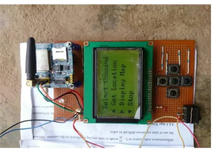
The keypad integrated GSM control system is made up of SIM900D GSM module, GLCD and five switches which serve as buttons for the user to control the robot. The robotic vehicle has a PIC18F2585 microcontroller, ultrasonic sensors, SIM900D GSM module and G16 GPS module. The keypad controlled security robot is implemented as shown in Fig. 5 to Fig. 8
Fig. 5. Hardware of the robotic vehicle
Start
Remote controller
GSM initialization
Display longitude and latitude
Display map of location of robot Does it get
location?
Select command function
Is map displayed?
[image:4.612.82.535.535.719.2]683
[image:5.612.101.525.76.422.2]©IJRASET: All Rights are Reserved
Fig. 6. Hardware of the keypad control system
[image:5.612.99.526.426.726.2]684
[image:6.612.80.548.75.313.2]©IJRASET: All Rights are Reserved
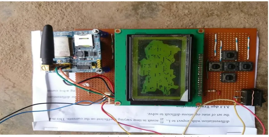
Fig. 8. GLCD screen showing the map where the robot is deployed
V. CONCLUSION
The GSM based robotic vehicle has been implemented using a PIC18F4680 and PIC18F2585 Microcontrollers. The robot can move around in terrains inaccessible by humans while being monitored by the operator of the robot with the aid of GPS and GSM facilities. The system provides information about the environment where the robot is deployed to the operator of the system by means of displaying the location and map of the area using GSM technology. The notification of the location includes the latitude and longitude of the area which can be sent to the GLCD.
REFERENCES
[1] S. Jena, S. K. Nayak, S. K. Sahoo, S. R. Sahoo, S. Dash and S. K. Sahoo,” Accelerometer Based Gesture Controlled Robot using Arduino”, International Journal Engineering Sciences & Technology,vol. 4, pp. 470–475, 2015
[2] K. Ranu and S. Renuak (2013),” GSM Mobile Control Robot Car”, 2nd Conference in Intelligent Computing and Communication, Robolab
[3] Bourdillon ,”Design Analysis of a GSM/RF-Based Remote Controlled Robotic Car”, Computer Engineering and Intelligent Systems, vol. 6, pp. 63- 74, 2015 [4] C.C. Dharmani, “Design with microcontrollers: IR Remote Controlled Car (PWM motor control using ATmega8)” (2014) [online] Available
from:www.dharmanitech.com/2009/01/ir-remotecontrolied-car-pwmmotor.html?m=1. [Accessed 08/01/2017].
[5] B. Sourangsu , “Design and Implementation of an Unmanned Vehicle Using a GSM Network with Microcontrollers”, International Journal of Science, Engineering and Technology Research, vol. 2, pp. 1-8, 201
[6] H. Mandakini, Thool, R.C. Pimple, “Design and Implementation of Unmanned Ground Vehicle Using GSM Network”, International Journal of Current Engineering and Technology,vol. 5, pp. 2772-2775, 2015