Comparison of Member Forces & Moments with
Different Member Properties in Seismic Zone III
Aashish Kumar Lakhera1, Prof. Vijay Kumar Shrivastava2, Prof. Yogesh Kumar Bajpai3
1
M-Tech Student (Structural Engineering) Gyan Ganga Inst. of Tech. & Science, Jabalpur M.P. India 2
Associate Professor, Civil Engg. Deptt. Gyan Ganga Inst. of Tech. & Science, Jabalpur M.P. India
3
H.O.D., Civil Engg. Deptt. Gyan Ganga Inst. of Tech. & Science, Jabalpur M.P. India
Abstract: In this research work the seismic analysis of the multistory building frame structure with A plan having a different geometry of 230mm x 230mm, 300mm x 300mm and 380mm x 380mm with constant geometry of columns and beams in each case. The building plan is symmetrical 24.38x24.38m of G+10 storey which is situated in seismic zone III, medium soil, response reduction factor 1.5 and damping ration 0.05 etc parameters are used. The analysis of the structure as per IS 1893 Part-I:2002, linear static methods by using Staad Pro V8i software. The structure analyzed in the term of support reaction and moments. The maximum reaction moment at Plan ‘C’ and minimum at plan ‘A’.
Keywords: Seismic Zone, Soil, Multi-storey building, Staad Pro etc.
I. INTRODUCTION
In all over the world the earthquakes have becomes a frequent event and very difficult to predict the intensity, location and occurrence of time of the earthquakes.in the design of the structures adequately for usual loads like dead load, wind loads etc. and the design approach adopted as Indian standard IS 1893 part-I:2002 “criteria for the Earthquake Resistant Design of the Structures” and is ensure that the structures possess at least a minimum strength to withstand minor occurring frequently the earthquake without any damage, resist the earthquakes without any significance structural damage through the some non-structural damage may occurs and the structure withstand the major earthquake without collapse
Seismic loading requires an understanding of the structural behavior under large inelastic deformations.
Behavior under this loading is fundamentally different from wind or gravity loading, requiring much more detailed analysis to assure acceptable seismic performance beyond the Elastic range. Some structural damage can be expected when the building experiences design ground motions because almost all building codes allow inelastic energy dissipation in structural system..
A. Literature Survey
1) D.R. Deshmukh, A.K. Yadav : Etc -He analyzed and design G+19 storied RC Building frame by using the Staad pro software, to analyzed and design of multi storey building frame which located in Pune city in seismic zone III and as per IS code, the value of seismic zone coefficient was taken as 0.06. 2.Narla Mohan etc all (2017)-He studied the comparative of Seismic and Wind analysis of the G+20, RC multistory commercial building frame with all seismic zone and different basic wind speed by using Etabs programming software.
2) Objective The Work: In this work the seismic analysis of the symmetrical building frame structure of 24.38m X 24.38m along to X and Z direction of G+10 storey, which is located to seismic zone III with medium soil conditions.
There are main objective of this works:
How to seismic evaluation of a building should be carried out.
To study the behavior of the structure under the action of Seismic Loads.
II. METHODOLOGY
In this work the Linear static Analysis method are adopted by using Staad Pro V8i software with different parameters like medium soil, damping ratio 0.05, R.F. 5, Importance factor 1.5 for important structures.
Selection of the seismic zone III as per IS 1893 Part-I:2002
Load Combinations
The building frame structure designing in 3D frame using Staad Pro v8i programming software.
Comparative analysis of the structure in the term of maximum support reaction, maximum reaction moment, maximum axial force.
A. Material And Geomerical Properties
1) We have been considered the following materials and geometrical properties. Density of R.C.C.: 25 KN/m3
Density of Masonry: 20 KN/m3.
Type Of Plan Category With Geometry Details
Name of Plan Member Name Geometry/Section Remarks
Plan “A” Columns 230mm X230mm Constant Geometry for
whole structure
Beams 230mm X230mm
Plan “C” Columns 380mm X 380mm Constant Geometry for
whole structure
Beams 380mm X 380mm
Details of the Dead Loads
Brick Masonry Wall Loads Remarks
For Floor Height 3.2 m = 0.25m x (3.2-0.23)m x 20 KN/m3
14.85 KN/m PLAN A
For Floor Height 3.2 m =
0.25m x (3.2-0.38)m x 20 KN/m3
14.10 KN/m PLAN C
Parapet wall
=
0.25m x (1)m x 20 KN/m3
5.0 KN/m
Floor Load
Slab Load = 0.15m x 25kN/m3 3.75 KN/m2 Assumed
150mm thick slab
Floor Finish = 1 KN/m2
Total Load = 4.75 KN/m2
2) Earthquake loads: All the building frame are analyzed in earthquake zone III and the seismic load calculation as per IS: 1893 (2002)
Table-4.3 Seismic Force Parameters for Proposed issue
S.No. Parameter Value As IS per Code
1. Zone- III 0.16 Table -2
2. Damping Ratio 0.05 Table-3
3. Importance Factor (I) 1.5 Table-6
4. Response Reduction
Factor (R.F.)
5 Table-7
5. Soil Site Factor (S.S.) Medium Soil
III. ANALYSIS AND RESULTS
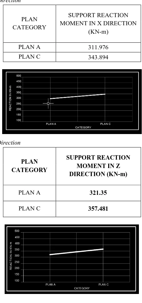
A. Support Reaction Moment In X Direction
PLAN CATEGORY
SUPPORT REACTION MOMENT IN X DIRECTION
(KN-m)
PLAN A 311.976
PLAN C 343.894
B. Support Reaction Moment In Z Direction
PLAN CATEGORY
SUPPORT REACTION MOMENT IN Z DIRECTION (KN-m)
PLAN A 321.35
C. Maximum Axial Force
PLAN
CATEGORY AXIAL FORCE IN KN
PLAN A 5512.399
PLAN C 5038.042
IV. CONCLUSIONS
A. The reaction moment if found that the plan category Plan C and minimum at plan ‘A’ that means that if the geometry increased then reaction moment is also increased.
B. The maximum axial force is observed at plan category Plan ‘A’ and minimum at plan ‘C’ that means the axial force is decreased with increased the geometry of the column and beams.
REFERENCES
[1] D.R. Deshmukh, A.K. Yadav, S. N Supekar, A. B. Thakur, H. P Sonawane, I. M. Jain “Analysis and Design of G+19 Storied Building Using Staad-Pro” D.R. Deshmukh .et al. Int. Journal of Engineering Research and Application, ISSN : 2248-9622, Vol. 6, Issue 7, ( Part -1) July 2016, pp.17-19
[2] Narla Mohan, A.Mounika Vardhan- Analysis of G+20 RC Building in Different Seismic Zones using ETABS- INTERNATIONAL JOURNAL OF PROFESSIONAL ENGINEERING STUDIES, Volume VIII /Issue 3 / MAR 2017
[3] Mandloi, Prof. Rajesh Chaturvedi- Seismic Analysis of Vertical Irregular Building with Time History Analysis, IOSR Journal of Mechanical and Civil Engineering (IOSR-JMCE) e-ISSN: 2278-1684,p-ISSN: 2320-334X, Volume 14, Issue 4 Ver. III (Jul. – Aug. 2017), PP 11-18
[4] Mohd Atif, Prof. Laxmikant Vairagade, Vikrant Nair- COMPARATIVE STUDY ON SEISMIC ANALYSIS OF MULTISTOREY BUILDING STIFFENED WITH BRACING AND SHEAR WALL, International Research Journal of Engineering and Technology (IRJET) e-ISSN: 2395-0056, p-ISSN: 2395-0072, Volume: 02 Issue: 05 | Aug-2015