Analysis of D-STATCOM for Power Quality
Enhancement in Distribution System
Nahid Hina Khan1, K. S. Verma2, Deependra Singh3
1, 2, 3
Dept of Electrical Engineering, KNIT, Sultanpur
Abstract: Electric troubles continually occur irrespective of time and place. This may additionally because an impact to the electric deliver as a result may additionally have an effect on the manufacturing enterprise and hinder the economic development in a rustic. The principal electric powered troubles that usually arise in strength signal structures are the electricity signal pleasant problems which have been mentioned by way of the electrical engineers around the sector, on account that troubles have turn out to be a primary issue because of the fast improvement of sophisticated and touchy gadget in the production and manufacturing industries. In distribution structures, the energy sign first-class issues can lessen the electricity signal provided to the customers from its nominal value. Voltage sag, harmonic, temporary, overvoltage and underneath voltage are fundamental impacts to a distribution system. The excellent system to solve this hassle at distribution systems at minimum fee is by using the use of Custom Power sign own family of D-STATCOM.
Keywords: Facts Devices, AC Transmission, SVC, STATCOM.
I. INTRODUCTION
The need for more efficient electricity systems management has given rise to innovative technologies in power generation and transmission. The combined cycle power station is a good example of a new development in power generation and flexible AC transmission systems, FACTS as they are generally known, are new devices that improve transmission systems. Worldwide transmission systems are undergoing continuous changes and restructuring.
They are becoming more heavily loaded and are being operated in ways not originally envisioned. Transmission systems must be flexible to react to more diverse generation and load patterns. In addition, the economical utilization of transmission system assets is of vital importance to enable utilities in industrialized countries to remain competitive and to survive in developing countries, the optimized use of transmission systems investments is also important to support industry, create employment and utilize efficiently scarce economic resources. Flexible AC Transmission Systems (FACTS) is a technology that responds to these needs. It significantly alters the way transmission systems are developed and controlled together with improvements in asset utilization, system flexibility and system performance.
FACTS devices are used for the dynamic control of voltage, impedance and phase angle of high voltage AC transmission lines. Below the different main types of FACTS devices are described: Static Var Compensator (SVC’s), the most important FACTS devices have been used for a number of years to improve transmission line economics by resolving dynamic voltage problems. The accuracy, availability and fast response enable SVC’s to provide high performance steady state and transient voltage control compared with classical shunt compensation. SVC’s are also used to dampen power swings, improve transient stability, and reduce system losses by optimized reactive power control.
Thyristor controlled series compensators (TCSCs) are an extension of conventional series capacitors through adding thyristor-controlled reactor. Placing a thyristor-controlled reactor parallel FACTS – For cost effective and reliable transmission of electrical energy with a series capacitor enables a continuous and rapidly variable series compensation system. The main benefits of TCSCs are increased energy transfer, dampening of power
Oscillations, dampening of sub synchronous resonances, and control of line power flow. STATCOMs are GTO (gate turn-off type thyristor) based SVC’s.
II. POWER QUALITY ISSUES
A. Importance of Power Quality
The definition of power quality conferring to Institute of Electrical and Electronic Engineers (IEEE) is ―The concept of powering and grounding sensitive electronic equipment in a manner suitable for the equipment‖. As the control quantity in electrical system mostly is voltage hence quite often it is referred as ‗voltage quality‘ because most of the time the controlled quantity is voltage. If supply voltage is dip because of a fault, then this will affect illumination of the light and the output power of induction motor. The interruptions of power nowadays are costly as depict in [3].
B. Common Disturbances In Power Systems
The Voltage Dip, Voltage Swell, Momentary interruptions, Transients, Voltage unbalance, Harmonics, DC offset etc. are termed as common disturbances. As per IEEE standard 1159(1995) recommendation the voltage dip, voltage swell and momentary interruptions are termed as short duration voltage variations.
III. OVERVIEW OF VOLTAGE SAG, SWELL AND FLUCTUATION
A. Voltage Sag
According to IEEE Std. 1159(1995), Voltage Dip magnitude range from 0.1 to 0.9 of nominal voltage and its durations from half-cycle to one minute. Furthermore, Voltage Sag may be classified [3] in three categories like Instantaneous, Momentary and temporary.
B. Voltage Swell
Voltage swell are not frequent as Voltage Dip but their occurrence are also for power system faults. If there is any single phase to ground fault occur then it will raise the voltage of the other phases, which causes Voltage Swell. The sudden switching on or disconnection of capacitor bank or large inductive load respectively can also create Voltage Swell in the electrical system [5]. In general, this is due to inappropriate ground or floating ground delta systems, where voltage magnitude may rise for ungrounded system if ground reference change takes place. The sudden load interruptions are other cause for Voltage Swell. The abrupt load change will force the current to change its value and for reduction in current, the voltage, will rise. The effects of Voltage Swell are more austere and damaging. It may create high voltage that will be the cause for electrical equipment failure due to overheating.
C. Voltage Fluctuation
It is defined as the repetitive and random variation of supply voltage from its nominal value for a certain period of time. The magnitude of the voltage variation is not more than 10%. Small magnitude of variation in a supply can give rise to voltage flicker which can be seen with naked eyes [5, 6]. These are caused when loads draw current with sudden or periodic variation. Examples of equipment that creates Voltage Fluctuations are arc welding, arc furnace, motor drives with cyclic operations etc.
IV. D-STATCOM OPERATION
[image:2.612.168.451.565.715.2]The shunt connected Static Synchronous Compensator is a custom power device and when it is placed in the utilization segment of power system then it is known as D-STATCOM.
Fig. 2: Capacitive and Inductive operation
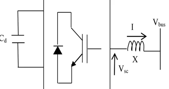
The D-STATCOM is a parallel-connected device based on Voltage Source Converter (VSC), incorporating advanced power electronics to deliver power quality solutions for utility and for commercial or industrial applications. A schematic diagram and corresponding phasor diagram showed in Fig. 1 and 2 respectively. The converter may arrange to act as a distribution STATCOM [7,8]. In its simplest implementation, a sine PWM technique has incorporated to generate desired gate signal for IGBT. The power flow across the inductor has governed by equations:
l = (1)
or in terms of real and imaginary power
P = × sin δ (2)
Q = × cos δ − (3)
Where: V converter output voltage
V ‐system voltage
X‐coupling reactance I‐converter current
δ ‐angle between V and V
The distribution STATCOM can operate in an identical manner to exchange real and reactive power flow with utility bus by controlling angle and voltage magnitude respectively between converter and bus [8-10]. The operating function of a distribution STATCOM in accordance with dc storage device is shown in Fig. 3. The flexibility provided by the rapid switching of the IGBTs allows more sophisticated control schemes, based on voltage space vector techniques. The compensator can control large reactive current along with transient when it operated in voltage regulation mode.
Fig. 3: Functions of D-STATCOM
The reactive current will decide the voltage regulation at the reference voltage, Vref, which will depends on the minimum and maximum range of current injected by the converter [10- 14]. Its i-v characteristic has a slope indicated in Fig. 4 and a voltage droop is normally used between 0.01-0.04 at maximum reactive power output. The regulated voltage is given by
[image:3.612.177.440.470.657.2]Fig. 4: i-v characteristics of STATCOM
V. MODELLING AND CONTROL OF D-STATCOM
A. Voltage Sag
[image:4.612.121.456.301.654.2]From the equivalent circuit, the dynamic equations governing the instantaneous values of the three phase voltages
Fig 5: Equivalent Circuit
Across two sides of D-STATCOM [11] and the current flowing into it are given by: (R + L )i = V −V (5)
Where, i = [(j( i i )]
V = (V ( V V )
The transformation in equation 6 is called as Park‘s transformation and after transforming to d-q-0 axis the equations in two phases are given by,
V V V
=τ
V V V
, i i i
=τ
i i i
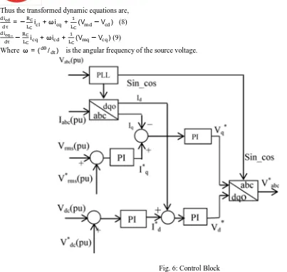
Thus the transformed dynamic equations are, =− i +ωi + (V −V ) (8)
− i +ωi + (V −V ) (9)
[image:5.612.40.443.68.450.2]Where ω= ( / ) is the angular frequency of the source voltage.
Fig. 6: Control Block
To consider the effect of reactive current on the magnitude of voltage at the point of common coupling, few assumptions has taken and these are:
1) The analysis is restricted to positive sequence components only.
2) All harmonic currents and voltages neglected.
The voltage magnitude, Vm at the point of common coupling is defined as: V = V + V (10)
B. Control Strategy
Fig. 7: Simulink diagram of controller block
Fig. 8 System Model
TABLE 1 Specification of the Power System Model Source 33kVrms, 50 Hz, Y- grounded Source Impedance 0.8929Ω , 16.58 mH
Feeder Line 25KM
Distribution 6MVA, 33kV/415V, 50 Hz, Transformer A-Y connected
Constant Load 415V, 50 Hz, 8.5MW
[image:6.612.142.480.378.726.2]Fig. 9: Simulink diagram representing the network
VI. RESULT AND DISCUSSION
A Distribution Static Synchronous Compensator (D- STATCOM ) is used to regulate voltage on a 25-kV distribution network. Two feeders (21 km and 2 km) transmit power to loads connected at buses number of B2 and B3. A shunt capacitor is used for power factor correction on the bus B2. The 600-V load is connected to the bus B3 through a 25kV/600V transformer represents a plant absorbing continuously changing currents, similar to an arc furnace, thus producing voltage flicker. The variable load current magnitude is modulated at a frequency of 5 Hz so that its apparent power varies approximately between 1 MVA and 5.2 MVA, while keeping a 0.9 lagging power factor. This load variation will allow you to observe the ability of the D- STATCOM to mitigate voltage flicker.
[image:7.612.93.502.464.574.2]The D- STATCOM regulates bus B3 voltage by absorbing or generating reactive power. This reactive power transfer is done through the leakage reactance of the coupling transformer by generating a secondary voltage in phase with the primary voltage (network side). This voltage is provided by a voltage-sourced PWM inverter. When the secondary voltage is lower than the bus voltage, the D- STATCOM acts like an inductance absorbing reactive power. When the secondary voltage is higher than the bus voltage, the D- STATCOM acts like a capacitor generating reactive power.
Fig 10:Power system model with variable load and voltage fluctuation
[image:7.612.72.535.609.716.2]Fig 12:Power and voltage wavefor representin voltage sag due to inductive load.
[image:8.612.87.522.575.714.2]Figure 12 shows that how the variation in source voltage are inserted the voltage values are: [1 1.06 0.94 1.0] pu at time instants [0 0.2 0.3 0.4 ] seconds. Here a constant active load is connected .
Fig 13:Power system with variable load for sag compensation with DSTATCOM
VII. CONCLUSION
This work illustrates the power quality improvement aspects in distribution system by DSTATCOM based on d-q-0 reference frame. The utilities like domestic, commercial and industrial are facing numerous PQ problems in the form of voltage dip, swell and voltage variations or fluctuations. The contributions of these power quality issues are severe in our existing electrical systems nowadays. In this work the estimation and mitigation of voltage sag, voltage swell, voltage fluctuation and reactive power limiting for different loading condition in utility by using Custom Power Devices. The D-STATCOM has taken as a compensating device, since it known for its flexibleness, easy implementation, dynamic load compensation & multifunctional operation. The model of D-STATCOM connected in shunt with a three-phase source feeding a constant and a variable load, which is develop using Simulink. The Simulated result demonstrates that D-STATCOM can consider as a feasible solution for solving voltage dip, swell and fluctuation problems.
REFERENCES
[1] Zakaria Anwar Zakaria, “Transient Studies of Custom Power Equipments and Static Var Compensator Using PSCAD,” International Journal of Electrical and Electronics Engineering 4:3 2009
[2] G. Sundar, “Digital Simulation Of D-Statcom For Voltage Fluctuations,” International Journal of Engineering Science and Technology Vol. 2(5), 2010, 1131-1135
[3] M. Sajedi Hir, “Analysis and Simulation of a D-STATCOM for Voltage Quality Improvement,” Australian Journal of Basic and Applied Sciences, 5(10): 864-870, 2011 ISSN 1991-8178
[4] K. Ram Mohan Reddy , “Implementation Of Custom Power Product Dstatcom In Power Sectork,” Vol. 1 No. 5 November 2012 www.garph.co.uk IJAREAS 45
[5] Gaurav Kumar Shah, “Systematic Survey for Role of Reactive Power Compensating Devices in Power System,” MIT International Journal of Electrical and Instrumentation Engineering, Vol. 3, No. 2, August 2013, pp. 89–94
[6] D. Mohan Reddy, “Mitigation Of Interruption & Voltage Sag, Swell Using A Cascaded Mli Based Dynamic Voltage Restorer,” International Journal of Electrical and Electronics Engineering Research (IJEEER) ISSN 2250-155X Vol. 3, Issue 2, Jun 2013, 153-170 TJPRC Pvt. Ltd.
[7] Hareesh Myneni, “Power Quality Enhancement by Current Controlled Voltage Source Inverter Based DSTATCOM for Load Variations,” IEEE IAS Joint Industrial And Commercial Power Systems / Petroleum And Chemical Industry Conference (ICPSPCIC) 2015
[8] K.P.Dinakaran, “ Design and Simulation of Transformerless Dynamic Voltage Restorer by Predictive Voltage Control,” International Journal of Engineering Science and Computing, April 2016 ,3302 http://ijesc.org/ DOI 10.4010/2016.766 ISSN 2321 3361,2016 IJESC
[9] U. Musa1, “Radial Distribution Network Enhancement With D-Statcom Using Bacterial Foraging Algorithm,” Arid Zone Journal Of Engineering, Technology And Environment, June, 2018; vol. 14(2):249-260. ISSN 1596-2490; e-ISSN 2545-5818.
[10] Eklas Hossain, “Analysis and Mitigation of Power Quality Issues in Distributed Generation Systems Using Custom Power Devices,” 2169-3536 2018 IEEE. Translations and content mining are permitted for academic research only. Personal use is also permitted, but republication/redistribution requires IEEE permission. See http://www.ieee.org/publications_standards/publications/rights/index.html for more information.
[11] Shafqat Hussain Memon, “ Total Harmonic Distortion (THD) Analysis of Grid Integrated Permanent Magnet Synchronous Generator (PMSG) With Full Scale Converter (FSC) Based Wind Farm,” IJCSNS International Journal of Computer Science and Network Security, VOL.18 No.12, December 2018
[12] Prabir Ranjan Kasari, “Analysis of D-STATCOM for Power Quality Enhancement in Distribution Network,” Proc. of the 2017 IEEE Region 10 Conference (TENCON), Malaysia, November 5-8, 2017


![Figure 12 shows that how the variation in source voltage are inserted the voltage values are: [1 1.06 0.94 1.0] pu at time instants [0 0.2 0.3 0.4 ] seconds](https://thumb-us.123doks.com/thumbv2/123dok_us/1233226.648735/8.612.97.514.306.541/figure-variation-source-voltage-inserted-voltage-instants-seconds.webp)
